Trust Care Let's Go Out User manual

SERVICE MANUAL
Outdoor rollator Let’s Go Out
from TrustCare

2
TABLE OF CONTENTS
Exchange of brake wire
Exchange of wire adjustment screw
Exchange of front wheel swiwel with screw
Exchange of front wheel swiwel without screw
Unfold hook adjustments
Exchange of linkage arm for folding
Parking brake adjustments
Mounting the middle joint of the folding cross
page 3
page 7
page 8
page 9
page 10
page 11
page 12
page 13

3
Year of manufacturing 2012.
Exchange of brake wire.
1. For disassembling the brake mecha-
nism, unscrew the double screw A and
the two screws holding the fender.
2. Pull out the rear wheel, the fender and
the mounting plate with the brake mecha-
nism.
4. Unscrew the locking sleeve at the bot-
tom end of the wire and disassemble the
brake mechanism..
5. Pull out the wire completely but leave
the sleeve in the tube which makes it
easier to insert the new wire..
6. Unscrew the two black screws and
pull down the brake housing so the brake
lever can be removed. Then remove the
wire completely.
7. Damaged parts such as handle tube,
brake lever, adjustment screw, or brake
housing can be exchanged if needed.
8. To remove the bottom plug, press both
snaplocks on either side of the tube.
3. First completely unscrew the adjust-
ment knob to release the bushel. Then
pull up the handle tube entirely from the
front leg tube until the wire is stretched.
9. Insert the new wire through the screw,
brake lever, and handle tube. Screw back
the brake housing.
Washer
Wire
Bottom plug
Bottom plug
Bushel
Locking
sleeve
A
B B
Rear leg
Locking sleeve
Distance
sleeve
Important!
Cut here
Form a loop
Important:
This part of the
wire on top
Wire guide
forming the
loop
Brake
mechanism
Insert the wire
guide into the
channel in the leg
A
B B
Washer
Wire
Bottom plug
Bottom plug
Bushel
Locking
sleeve
A
B B
Rear leg
Locking sleeve
Distance
sleeve
Important!
Cut here
Form a loop
Important:
This part of the
wire on top
Wire guide
forming the
loop
Brake
mechanism
Insert the wire
guide into the
channel in the leg
A
B B
Washer
Wire
Bottom plug
Bottom plug
Bushel
Locking
sleeve
A
B B
Rear leg
Locking sleeve
Distance
sleeve
Important!
Cut here
Form a loop
Important:
This part of the
wire on top
Wire guide
forming the
loop
Brake
mechanism
Insert the wire
guide into the
channel in the leg
A
B B
Washer
Wire
Bottom plug
Bottom plug
Bushel
Locking
sleeve
A
B B
Rear leg
Locking sleeve
Distance
sleeve
Important!
Cut here
Form a loop
Important:
This part of the
wire on top
Wire guide
forming the
loop
Brake
mechanism
Insert the wire
guide into the
channel in the leg
A
B B
Washer
Wire
Bottom plug
Bottom plug
Bushel
Locking
sleeve
A
B B
Rear leg
Locking sleeve
Distance
sleeve
Important!
Cut here
Form a loop
Important:
This part of the
wire on top
Wire guide
forming the
loop
Brake
mechanism
Insert the wire
guide into the
channel in the leg
A
B B
Washer
Wire
Bottom plug
Bottom plug
Bushel
Locking
sleeve
A
B B
Rear leg
Locking sleeve
Distance
sleeve
Important!
Cut here
Form a loop
Important:
This part of the
wire on top
Wire guide
forming the
loop
Brake
mechanism
Insert the wire
guide into the
channel in the leg
A
B B
Washer
Wire
Bottom plug
Bottom plug
Bushel
Locking
sleeve
A
B B
Rear leg
Locking sleeve
Distance
sleeve
Important!
Cut here
Form a loop
Important:
This part of the
wire on top
Wire guide
forming the
loop
Brake
mechanism
Insert the wire
guide into the
channel in the leg
A
B B
Washer
Wire
Bottom plug
Bottom plug
Bushel
Locking
sleeve
A
B B
Rear leg
Locking sleeve
Distance
sleeve
Important!
Cut here
Form a loop
Important:
This part of the
wire on top
Wire guide
forming the
loop
Brake
mechanism
Insert the wire
guide into the
channel in the leg
A
B B
Adjustment screw
Handle tube
Housing
Brake lever

4
10. Put the bottom plug on the wire and
press it into the handle tube. Add the
sleeve to the wire.
11. Put the end of the wire into the older
wire sleeve and use this as a guide to lead
the new wire into the rear leg.
12. Push the handle tube down to the bot-
tom and screw the height adjustment knob
back in place.
Washer
Wire
Bottom plug
Bottom plug
Bushel
Locking
sleeve
A
B B
Rear leg
Locking sleeve
Distance
sleeve
Important!
Cut here
Form a loop
Important:
This part of the
wire on top
Wire guide
forming the
loop
Brake
mechanism
Insert the wire
guide into the
channel in the leg
A
B B
Washer
Wire
Bottom plug
Bottom plug
Bushel
Locking
sleeve
A
B B
Rear leg
Locking sleeve
Distance
sleeve
Important!
Cut here
Form a loop
Important:
This part of the
wire on top
Wire guide
forming the
loop
Brake
mechanism
Insert the wire
guide into the
channel in the leg
A
B B
Washer
Wire
Bottom plug
Bottom plug
Bushel
Locking
sleeve
A
B B
Rear leg
Locking sleeve
Distance
sleeve
Important!
Cut here
Form a loop
Important:
This part of the
wire on top
Wire guide
forming the
loop
Brake
mechanism
Insert the wire
guide into the
channel in the leg
A
B B
Washer
Wire
Bottom plug
Bottom plug
Bushel
Locking
sleeve
A
B B
Rear leg
Locking sleeve
Distance
sleeve
Important!
Cut here
Form a loop
Important:
This part of the
wire on top
Wire guide
forming the
loop
Brake
mechanism
Insert the wire
guide into the
channel in the leg
A
B B
Washer
Wire
Bottom plug
Bottom plug
Bushel
Locking
sleeve
A
B B
Rear leg
Locking sleeve
Distance
sleeve
Important!
Cut here
Form a loop
Important:
This part of the
wire on top
Wire guide
forming the
loop
Brake
mechanism
Insert the wire
guide into the
channel in the leg
A
B B
Washer
Wire
Bottom plug
Bottom plug
Bushel
Locking
sleeve
A
B B
Rear leg
Locking sleeve
Distance
sleeve
Important!
Cut here
Form a loop
Important:
This part of the
wire on top
Wire guide
forming the
loop
Brake
mechanism
Insert the wire
guide into the
channel in the leg
A
B B
Washer
Wire
Bottom plug
Bottom plug
Bushel
Locking
sleeve
A
B B
Rear leg
Locking sleeve
Distance
sleeve
Important!
Cut here
Form a loop
Important:
This part of the
wire on top
Wire guide
forming the
loop
Brake
mechanism
Insert the wire
guide into the
channel in the leg
A
B B
Washer
Wire
Bottom plug
Bottom plug
Bushel
Locking
sleeve
A
B B
Rear leg
Locking sleeve
Distance
sleeve
Important!
Cut here
Form a loop
Important:
This part of the
wire on top
Wire guide
forming the
loop
Brake
mechanism
Insert the wire
guide into the
channel in the leg
A
B B
13. Mount the yoke, spring and locking
sleeve. Check the functon of the brake
when the wire has a loop, see picture.
Then cut the protruding part of the wire.
14. Use the wire guide to form a loop
inside the rear leg. Make sure that the
wire is not pinched when it is inserted
into the rear leg.
15. Push the wire guide entirely into the
reat leg. Then push in the mounting plate
for the rear wheel into the same channel
in the rear leg profile.
16. Before putting in the mounting plate,
make sure that the cavities in the yoke
correspond to the rubber parts.
17. Make sure that the distance sleeve
is included when the mounting plate is
pushed in. Then add the fender.
18. Screw the black double screw back
in place and fix the two screws that hold
the fender.
old wire
sleeve
New wire

5
Year of manufacturing from 2013 onward.
Exchange of brake wire.
2. Pull out the rear wheel, fender, and
mounting plate with the brake mecha-
nism, and the plastic wire guide inside the
rear leg.
4. Unscrew the height adjustment knob
and move the handle tube a little upward.
Unscrew the housing around the brake
with the screw on the side.
5. Take out the end of the wire from the
lever and the screw through the side
slits.
6. Pull out the wire entirely through the
rear leg. Keep the spring and use it on
the new wire.
7. Thread the spring over the upper end
of the wire and move it down to the bot-
tom.
8. Push the upper end of the wire into
the rear leg. Use a screwdriver as help to
guide the wire into the upper tube.
3. Take off the brake yoke from the wire.
9. Pull out the wire in the upper end and
put it into the handle tube all the way up
to the hole for the brake mechanism.
Adjustment
screw
Washer
Brake lever
Wire
Front leg tube
Bottom plug
Bottom plug
Bushel
Handle tube
A
B B
Fender
Wire guide
Rear leg
Rear leg Distance
sleeve
Distance sleeve
N.B.!
Form a loop
Important:
This part of the
wire on top
Wire guide
to form the
loop
Brake
mechanism
Insert rhe wire
guide into the
channel in the leg
A
B B
Slit
Spring
Adjustment screw
1. For disassembling the brake mecha-
nism, unscrew the double screw A and
the two screws holding the fender.

6
10. Use a bent steel wire to pull the end of
the brake wire out through the hole.
11. Put the wire into the brake lever and
the screw through the side slits. Exchange
any damaged details before assembly.
12. Skruva på kåpan, montera bottenplug-
gen i röret och skjut ner handtagsröret i
frambensröret hela vägen ner.
Adjustment
screw
Washer
Brake lever
Wire
Front leg tube
Bottom plug
Bottom plug
Bushel
Handle tube
A
B B
Fender
Wire guide
Rear leg
Rear leg Distance
sleeve
Distance sleeve
N.B.!
Form a loop
Important:
This part of the
wire on top
Wire guide
to form the
loop
Brake
mechanism
Insert rhe wire
guide into the
channel in the leg
A
B B
Slit
Spring
Adjustment screw
Adjustment
screw
Washer
Brake lever
Wire
Front leg tube
Bottom plug
Bottom plug
Bushel
Handle tube
A
B B
Fender
Wire guide
Rear leg
Rear leg
Distance
sleeve
Distance sleeve
N.B.!
Form a loop
Important:
This part of the
wire on top
Wire guide
to form the
loop
Brake
mechanism
Insert rhe wire
guide into the
channel in the leg
A
B B
Slit
Spring
Adjustment screw
Adjustment
screw
Washer
Brake lever
Wire
Front leg tube
Bottom plug
Bottom plug
Bushel
Handle tube
A
B B
Fender
Wire guide
Rear leg
Rear leg Distance
sleeve
Distance sleeve
N.B.!
Form a loop
Important:
This part of the
wire on top
Wire guide
to form the
loop
Brake
mechanism
Insert rhe wire
guide into the
channel in the leg
A
B B
Slit
Spring
Adjustment screw
Adjustment
screw
Washer
Brake lever
Wire
Front leg tube
Bottom plug
Bottom plug
Bushel
Handle tube
A
B B
Fender
Wire guide
Rear leg
Rear leg
Distance
sleeve
Distance sleeve
N.B.!
Form a loop
Important:
This part of the
wire on top
Wire guide
to form the
loop
Brake
mechanism
Insert rhe wire
guide into the
channel in the leg
A
B B
Slit
Spring
Adjustment screw
Adjustment
screw
Washer
Brake lever
Wire
Front leg tube
Bottom plug
Bottom plug
Bushel
Handle tube
A
B B
Fender
Wire guide
Rear leg
Rear leg Distance
sleeve
Distance sleeve
N.B.!
Form a loop
Important:
This part of the
wire on top
Wire guide
to form the
loop
Brake
mechanism
Insert rhe wire
guide into the
channel in the leg
A
B B
Slit
Spring
Adjustment screw
Adjustment
screw
Washer
Brake lever
Wire
Front leg tube
Bottom plug
Bottom plug
Bushel
Handle tube
A
B B
Fender
Wire guide
Rear leg
Rear leg Distance
sleeve
Distance sleeve
N.B.!
Form a loop
Important:
This part of the
wire on top
Wire guide
to form the
loop
Brake
mechanism
Insert rhe wire
guide into the
channel in the leg
A
B B
Slit
Spring
Adjustment screw
16. Before the mounting plate is pushed
in, put the distance sleeve into the yoke.
Check that the rubber parts are included.
17. Make sure that the distance sleeve is
inside the yoke and that the rubber parts
don’t fall off. Put the fender in place.
18. Screw back the black double screw
A and the two screws B that hold the
fender.
Adjustment
screw
Washer
Brake lever
Wire
Front leg tube
Bottom plug
Bottom plug
Bushel
Handle tube
A
B B
Fender
Wire guide
Rear leg
Rear leg Distance
sleeve
Distance sleeve
N.B.!
Form a loop
Important:
This part of the
wire on top
Wire guide
to form the
loop
Brake
mechanism
Insert rhe wire
guide into the
channel in the leg
A
B B
Slit
Spring
Adjustment screw
13. Mount the yoke and the spring on
the wire. Check the functon of the brake
when the wire has a loop, see picture.
14. Use the wire guide to form a loop
inside the rear leg. Make sure that the
wire is not pinched when it is inserted
into the rear leg.
15. Push the wire guide entirely into the
reat leg. Then push in the mounting plate
for the rear wheel into the same channel
in the rear leg profile.

7
Exchange of wire adjustment screw (whole or damaged)
i rollatorn Let’s Go Out serie 2012 12 och framåt.
1. Unscrew the screw that holds the black brake housing. 2. Push the brake housing down.
3. To take out the wire, make sure that the slits in the screw and
the brake lever correspond. If the screw is broken, use a small
screwdriver to turn it to the correct position.
5. Screw the new screw down to the bottom. Make sure the
slits correspond and put back the wire.
6. Push back the brake housing and screw it in place. Adjust
the wire tensin with the new screw.
www.trustcare.se
4. The wire can now be taken out and the screw removed. Use
the screwdriver if the screw is broken.
Year of manufacturing from 2013 onward.

8
Year of manufacturing 2012.
Exchange of front wheel swivel with screw fixture.
1. Remove the black plastic cap over the
front swivel bearing
2. Unscrew the screw with an Allen key.
Put a screwdriver into the joint in the
plastic if the bearing rotates.
3. Pull out the front swivel and remove the
existing bearing.
4. The new bearing is in three parts.
One plastic part with screw fixture, one
shorter plastic part, one brass sleeve.
5. Put the sleeve in the top of the front
swivel. Put some grease between the
sleeve and the swivel.
6. Put the two halves together. Make sure
that the top of the swivel is locked inside
the bearing and will not fall out.
7. Press the new bearing into the tube.
Bump against the floor if needed.
8. Mount the washer and the screw.
Tighten the screw securely.
9. Put on the black plastic cap. If neces-
sary fix it with some glue.
Joint
Snap lock
Joint
Snap lock
Joint
Snap lock
Joint
Snap lock
Joint
Snap lock
Joint
Snap lock
Joint
Snap lock
Joint
Snap lock
Joint
Snap lock

9
1. Remove the plastic cap above the front wheel bearing. 2. Knock the existing bearing out of the tube with a hammer.
Use a piece of metal between the hammer and bearing.
3. Mount the new bearing. Put the metal sleeve on the swivel
and add some grease inbetween. Put the two plastic halves
together. Make sure that the groove locks the swivel inside.
4. Press the new bearing into the tube. Use a piece of wood
inbetween and knock it in with a hammer all the way up. Put
back the plastic cap.
Year of manufacturing from 2013 onward.
Exchange of front wheel swivel without screw fixture.
1. LYFT AV PLASTLOCKET
Snap lock
BYTE AV FRAMGAFFELLAGER
PÅ LET’S GO OUT
2. KNACKA UT DET
BEFINTLIGA LAGRET
MED EN HAMMARE
OCH EN METALLBIT
SOM MELLANLÄGG
3. TA LOSS LAGRET
FRÅN FRAMGAFFELN
OCH SÄTT PÅ DET NYA
LAGRET (3 DELAR).
Plastic
Groove
Metal sleeve
Plastic
1. LYFT AV PLASTLOCKET
Snap lock
BYTE AV FRAMGAFFELLAGER
PÅ LET’S GO OUT
2. KNACKA UT DET
BEFINTLIGA LAGRET
MED EN HAMMARE
OCH EN METALLBIT
SOM MELLANLÄGG
3. TA LOSS LAGRET
FRÅN FRAMGAFFELN
OCH SÄTT PÅ DET NYA
LAGRET (3 DELAR).
Plastic
Groove
Metal sleeve
Plastic
1. LYFT AV PLASTLOCKET
Snap lock
BYTE AV FRAMGAFFELLAGER
PÅ LET’S GO OUT
2. KNACKA UT DET
BEFINTLIGA LAGRET
MED EN HAMMARE
OCH EN METALLBIT
SOM MELLANLÄGG
3. TA LOSS LAGRET
FRÅN FRAMGAFFELN
OCH SÄTT PÅ DET NYA
LAGRET (3 DELAR).
Plastic
Groove
Metal sleeve
Plastic
1. LYFT AV PLASTLOCKET
Snap lock
BYTE AV FRAMGAFFELLAGER
PÅ LET’S GO OUT
2. KNACKA UT DET
BEFINTLIGA LAGRET
MED EN HAMMARE
OCH EN METALLBIT
SOM MELLANLÄGG
3. TA LOSS LAGRET
FRÅN FRAMGAFFELN
OCH SÄTT PÅ DET NYA
LAGRET (3 DELAR).
Plastic
Groove
Metal sleeve
Plastic

10
1. Below the seat of the rollator there is a
hook that takes hold around a peg inside
the black plastic part. The peg consists of
a spring dowel pin with a brass sleeve
around it.
2. First check that the peg is in place
inside the black plastic part, that it is not
damaged or missing.
4. File carefully with a small round file to
make the hook deeper. Take it little by
little and test the function.
5. Test the function by lifting the two
metal tubes that hold the seat. The hook
must not come loose. When the seat is
lifted in the middle hole the hook should
release and the rollator fold.
6. If the hook does not climb over the
peg when the seat ends are pushed down
the hook will not reach the position where
it locks. The rollator is not fully unfolded.
8. When the end tubes on the seat are
pushed down the hook should climb over
the peg and lock firmly.
3. If the hook will not lock around the
peg and loses its grip accidentaly it is
because the hook has not the correct
shape.
7. Adjust carefully with a file the bottom
side of the hook. Take it little by little
and check the function until the hook
climbs over the peg and locks.
9. The wire that lifts the hook when the
rollator is to be folded needs a double loop
to work properly.
Wire
loop
Seat
Hook stuck
Hook
Locking peg
Black linkage arm
Locking
peg
Opening
1. Below the seat of the rollator there is a
metal hook and a locking peg inside the
black linkage arm. The locking peg is a
spring dowel pin with a brass sleeve.
2. First make sure that the locking peg is
not damaged or missing. If it is missing it
must be replaced.
3. If the hook is not locking around the peg
and releases involuntarely although the peg
is intact it is because the hook is damaged
and has an incorrect shape.
4. File carefully with a small round file to
make the tip of the hook deeper. Take it
little by little and test the function.
5. Test by lifting the rollator in the two
metal tubes that holds the seat. The hook
should not release. When the seat is
lifted in the hole the hook should release.
6. If the hook does not pass the peg
when the ends of the seat are pressed
down the hook will never lock around the
peg. The rollator will not unfold correctly.
7. File carefully on the bottom side of the
hook to give it a shape that allows it to
pass the peg. Take it little by little and
test the function.
8. When the ends of the seat are pressed
down the hook should pass the locking
peg and lock safely.
9. The wire that releases the hook when
the seat is lifted in the middle hole must
have a double loop to function correctly.
Year of manufacturing 2012.
Unfold hook adjustments.

11
1. Drill out the rivets that hold the plastic linkage arm to the metal frame of the rollator. 2. Remove the plastic part. Keep the metal
reinformcement bar that is inside.
3. Mount the new plastic arm with the metal
reinforcement bar. On the left side the hook for
folding should also be monted.
4. Mount the parts using screws, washers, and nuts. Add a drop of Loctite to fix
the nuts.
Exchange of the linkage arm for folding.
1. Drill out the rivets
that hold the plastic arm in place.
EXCHANGE OF THE PLASTIC LINKAGE ARM ON THE LET’S GO OUT ROLLATOR
2. Remove the damaged part.
3. In the plastic part there is a
reinforcement metal bar.
Put the metal bar inside the
new part.
4. Replace the damaged part
with the new one. On the right side
also mount the hook and the spring.
5. Mount the screws, washers
and nuts. Secure the nuts with
one drop of Loctite.
Citadellsvägen 23, 21118 Malmö, Sweden
www.trustcare.se
12
Brake lever
Brake housing (cross section)
Brake wire
B
A
C
D
Brake lever
Brake housing (cross section)
Brake wire
B
A
C
D
Brake lever
Brake housing (cross section)
Brake wire
B
A
C
D
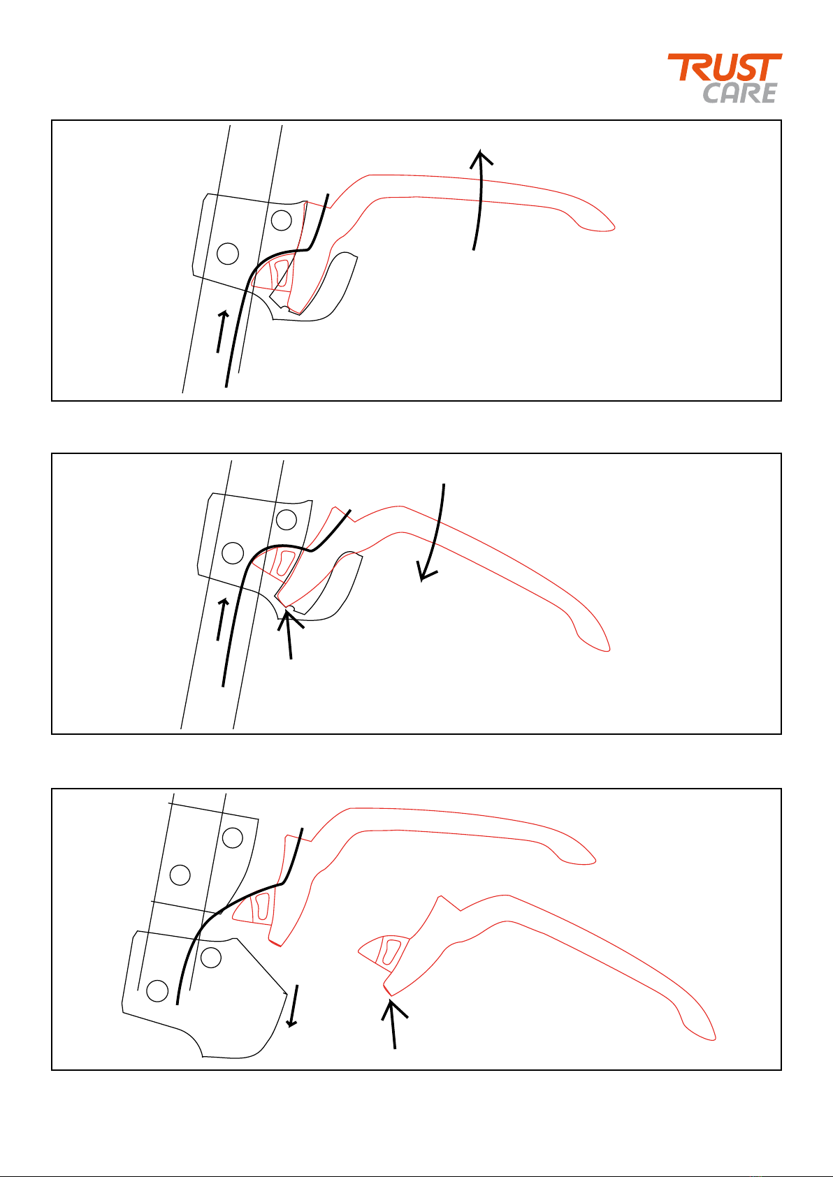
1. This is the function of the brake system on Let’s Go Out. When the brake lever is pulled up (A) the wire is stretched and the rollator
brakes. The parking prake is activated by pushing the lever down so it will lock in lowest position.
2. When the lever is pushed down th wire is stretched. The bottom end of the lever falls down into the cavity (C) and locks.
3. If the lever does not lock in the cavity, remove the two screws in the brake housing and push the housing down. Behind one of
the screws there is a washer, don’t lose it. File the corner at (D) to make it sharper so it will lock better in the cavity. If the brake
lever still does not lock, there could be a damage inside the brake housing and it must be replaced.
Year of manufacturing 2012.
Parking brake adjustments.

13
1. These are the parts of the joint and how they should be mounted together.
2. The tubes of the folding cross should be placed between the washers according to this sketch.
3. Tighten the dome nut securely. Fix the nut with a drop of Loctite so it will not fall off. The metal sleeve serves as a fixture peg for
the hook when the rollator is folded.
Year of manufacturing 2012.
Mounting the middle joint of the folding cross.
Dome nut Metal sleeve Screwplastic washers
Brickor av metall
Front side
of rollator
Front side
of rollator
Rear side
of rollator
Rear side
of rollator
Metal sleeve
This manual suits for next models
1
Table of contents
Other Trust Care Mobility Aid manuals

Trust Care
Trust Care LFR101 User manual

Trust Care
Trust Care LET'S ENJOY User manual

Trust Care
Trust Care Let's Move Outdoor User manual

Trust Care
Trust Care LSG101 User manual

Trust Care
Trust Care Let's Go User manual

Trust Care
Trust Care Reddot award User manual

Trust Care
Trust Care Let's Go PR30285-SL User manual

Trust Care
Trust Care Let's Shop User manual

Trust Care
Trust Care Let'sGo User manual

Trust Care
Trust Care LGU330 User manual


