RIVETING CHAIN PINS
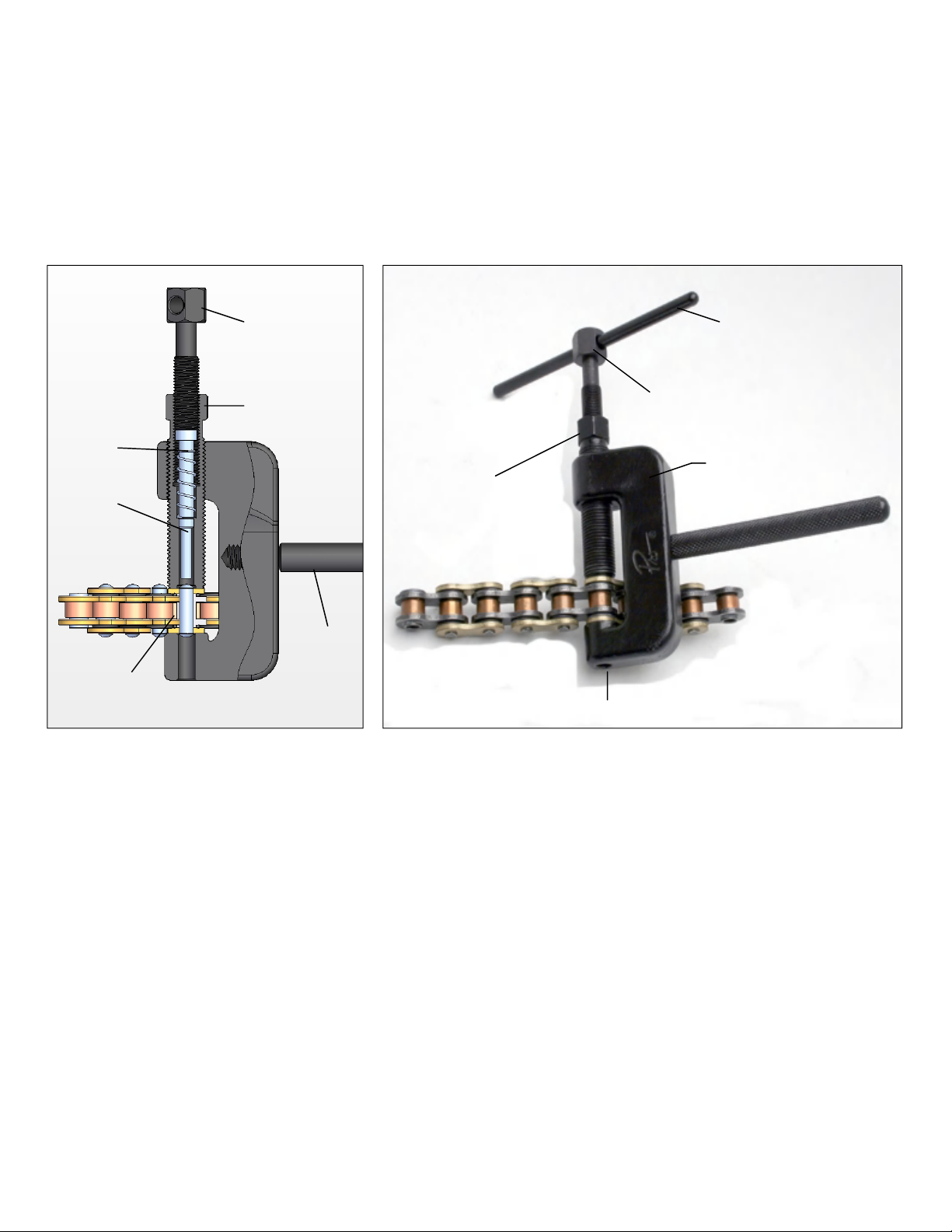
Assemble the tool as shown in Image E for riveting hollow-nosed master link pins. Thread the body bolt into the
body. Insert the rivet tip into the spring and drop them into the body bolt with the spring under the tip head. (Refer
to internal diagram with Image B). Thread the extractor bolt into the body bolt above the tip. Place the anvil in
in the hole in the tool body per Image G.
1. The new master link side plate should already be pressed on(see Pressing Side Plates) so that the chain pin protrudes
past the face of the master link side plate. Refer to the chain manufacturer’s specifications for the proper protrusion
distance. Do not attempt to re-use broken master links, or use a clip on a rivet type master link. Position the tool over
the chain pin to be riveted, with the hollow end of the chain pin facing the rivet tip, and the solid end facing the anvil.
2. Make sure the rivet tip is withdrawn enough to clear the end of the chain pin. Tighten the body bolt securely
against the side plate of the chain, but do not over-tighten.
3. Using a Philips screwdriver or a 14mm wrench, tighten the extractor bolt tightly until the rivet tip spreads the hollow
nose of the chain pin. The end of the chain pin should be flared over the side plate just enough so that the side plate is
solidly held in place. Repeat this procedure on the other chain pin. The amount of flare of a rivet type master link varies
among chain manufacturers. Some specify as little as 0.006” and generally no more than 0.028” (refer to manufacturers
specification to determine proper flare for your chain). This is a very small amount of flare. Do not attempt to flare the
chain pin flush with the side plate, or the chain pin can crack and be weakened, and you risk damaging the tool as well.
Measure the un-flared chain pin with a caliper, and then check the flare often with the caliper to insure you do not over-
flare the chain pin. One turn of the push bolt equals approx. 0.040” of travel, so a typical flare will require less than a full
turn. Image F shows a properly flared hollow-nosed master link.
4. Withdraw the tool from the chain, and visually check that both chain pins show the same size flares. Check that the
riveted-on side plate is in alignment with the side plates of adjacent chain links.
WARNING - It is very important that chain master links be clipped or riveted properly. Improper installation can
lead to great bodily harm or death. If you are unfamiliar or uncomfortable with this process, please have your
work supervised by a qualified technician or bring your vehicle to a qualified facility for repair.
Page 4 of 4
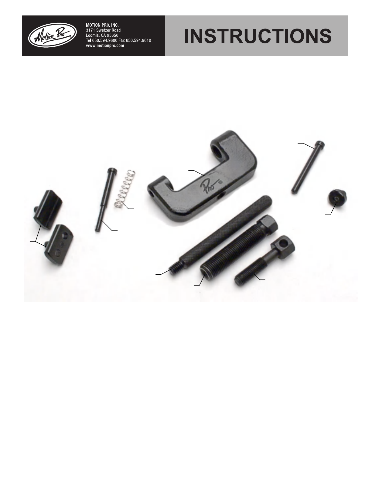
Extractor Bolt
Body Bolt
Rivet Tip and
Spring inside
Body Bolt
Hole in tool Body
Properly flared chain pins.
Large Anvil
10/2016I08-0467