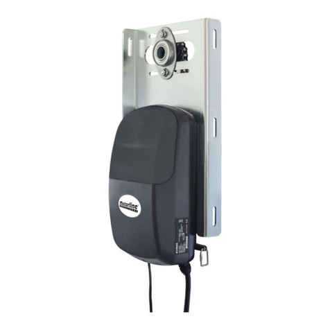
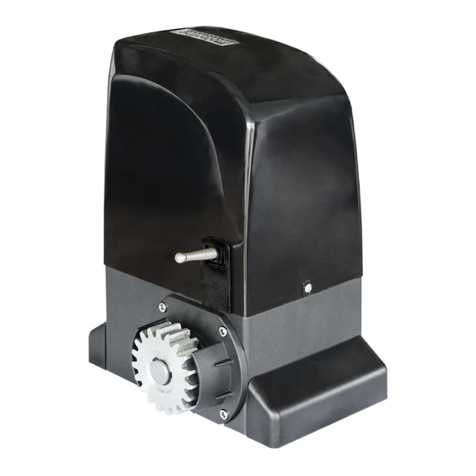
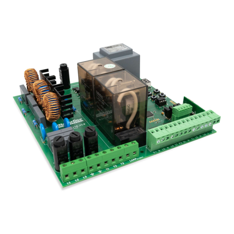
Motorline TELICA Use and care manual

V2.1
REV. 02/2019
TELICA EN
USER’S AND INSTALLER’S MANUAL

A B
1B
3A
3B
4A
4A
6A
7A
8A
6B
7B
9B
3B
4B
4B
5A
5A
5B
ENEN
STANDARDS TO FOLLOW
INSIDE THE PACKAGE
DIMENSIONS
EMERGENCY UNLOCK
INSTRUCTIONS FOR FINAL CONSUMERS
INSTRUCTIONS FOR SPECIALIZED INSTALLERS
TECHNICAL SPECIFICATIONS
INSTALLATION MEASURES
SUPPORTS INSTALLATION
. SAFETY INSTRUCTIONS
. THE PACKAGE
. OPERATOR
. INSTALLATION
. TROUBLESHOOTING
. CONTENT . SAFETY INSTRUCTIONS
INDEX STANDARDS TO FOLLOW
AUTOMATISM INSTALLATION
ARMS INSTALLATION
MICROS ADJUSTMENT
Vac MOTOR
Vdc MOTOR
. COMPONENTS TEST
EXTERNAL UNLOCK
. CONNECTION SCHEME
ATTENTION:
This product is certified in accordance with European Community
(EC) safety standards.
This product complies with Directive 2011/65/EU of the European
Parliament and of the Council, of 8 June 2011, on the restriction
of the use of certain hazardous substances in electrical and
electronic equipment.
(Applicable in countries with recycling systems).
This marking on the product or literature indicates that the
product and electronic accessories (eg. Charger, USB cable,
electronic material, controls, etc.) should not be disposed of
as other household waste at the end of its useful life. To avoid
possible harm to the environment or human health resulting
from the uncontrolled disposal of waste, separate these items
from other types of waste and recycle them responsibly to
promote the sustainable reuse of material resources. Home users
should contact the dealer where they purchased this product or
the National Environment Agency for details on where and how
they can take these items for environmentally safe recycling.
Business users should contact their vendor and check the terms
and conditions of the purchase agreement. This product and its
electronic accessories should not be mixed with other commercial
waste.
This marking indicates that the product and electronic accessories
(eg. charger, USB cable, electronic material, controls, etc.) are
susceptible to electric shock by direct or indirect contact with
electricity. Be cautious when handling the product and observe all
safety procedures in this manual.
V/V MOTOR (MC)
V MOTOR (MC)

A B
ENEN
. SAFETY INSTRUCTIONS. SAFETY INSTRUCTIONS
STANDARDS TO FOLLOWSTANDARDS TO FOLLOW
properly.
• If the automation is to be installed at a level higher than 2,5 m above ground
level or other level of access, , should be followed the minimum safety and
health requirements for the use of work equipment workers at work in Directive
2009/104/EC of the European Parliament and of the Council of 16th September
of 2009.
• In the case of the equipment where the automation will be installed, have
a pedestrian door, be aware that it must be closed when the automation is
activated.
• After installation, make sure that the mechanism is properly adjusted and that
the protection system and any manual unlocker works correctly.
• In order to protect the electrical cables against mechanical stress, you should
use conduit for the electrical wires, essentially on the power cable.
• When programming the control unit on the control board, you should pay
particular attention to touching only the location intended for that purpose.
Failure to do so may result in electric shock.
• It is important for your safety that these instructions are followed.
• Keep these instructions in a safe place for future reference.
• The ELECTROCELOS S.A. is not responsible for the improper use of the product,
or other use than that for which it was designed.
• The ELECTROCELOS S.A. is not responsible if safety standards were not taken
into account when installing the equipment, or for any deformation that may
occur.
• The ELECTROCELOS S.A. is not responsible for insecurity and malfunction of the
product when used with components that were not sold by the them.
• This product was designed and manufactured strictly for the use indicated in
this manual.
• Any other use not expressly indicated may damage the product and/or can
cause physical and property damages, and will void the warranty.
• Do not make any changes to the automation components and/or their
accessories.
• Keep remote controls away from children, to prevent the automated system
from being activated involuntarily.
• The customer shall not, under any circumstances, attempt to repair or tune the
automatism. Must call qualified technician only.
• The installer must have certified professional knowledge at the level of
mechanical assemblies in doors and gates and control board programmation.
He should also be able to perform electrical connections in compliance with all
applicable regulations.
• The installer should inform the customer how to handle the product in an
emergency and provide him the manual.
• This device can be used by children 8 year old or older and persons whose
physical, sensory or mental capacities are reduced, or by persons without
experience or knowledge if they have received supervision or instructions on
the use of the device in a safe manner and understood the hazards involved.
Children should not play with the device. Cleaning and maintenance by the user
must not be carried out by unsupervised children.
• Automatism powered by very low safety voltage, with electronic board / control
board / control unit. (24 Vdc)
• Before installing, the installer must verify that the temperature range indicated
on the automatism is appropriate to the location of the installation.
• Before installing, the installer must verify that the equipment to be automated
is in good mechanical condition, correctly balanced and opens and closes

A B
155mm
240mm
220mm
265mm
525mm
415mm
ENEN
. THE PACKAGE . OPERATOR
INSIDE THE PACKAGE DIMENSIONS
TECHNICAL SPECIFICATIONS
Components on the 2 motor's package:
01 • 02 articulated motors
02a • 01 articulated right arm
02b • 01 articulated left arm
03 • 02 4 channels remote controls
04 • 02 frontal supports
05 • 02 motor supports
06 • 02 unlock keys
07 • 01 photocells set
08 • 01 user manual
Kit components:
The dimensions of the TELICA automation are the following:
Kit package:
24Vdc 230Vac
• Power supply 24Vdc 230Vac
• Power 220W 380W
• Force 200 Nm 200 Nm
• Working frequence Intensive Use 50 %
• Capacitor -12,5 F
• Protection grade IP53 IP53
• Noise LpA <= 50dB (A) LpA <= 50dB (A)
• Thermal protection - 120°C
• Operating temperature -25°C to 55°C -25°C to 55°C
• RPM 1,30 RPM 1,10 RPM
Fig. 1
Fig. 4
Fig. 2
Fig. 3
07•03•
06•
04•
05•02b•
08•
01•
02a•
Components on the 1 motor's package:
01 • 01 articulated motor
02a • 01 articulated direito/esquerdo arm
03 • 02 4 channels remote controls
04 • 01 frontal support
05 • 01 motor's support
06 • 01 unlock key
07 • 01 photocells set
08 • 01 user manual
This automation is suitable for leaves up to 2.5 meters wide. For leaves with a width higher
than 2,50 meters, we recommend the use of an electric lock.

A B
1
2
3
B
A
AB
CDE
450mm
16mm
ENEN
. INSTALLATION
EMERGENCY UNLOCK INSTALLATION MEASURES
. INSTALLATION
•Thetablebelowindicates
the measure which quota
Bshould have in function
of the quota Ameasure.
SUPPORTS INSTALLATION
1• Drill holes for M8 screw anchors.
• You must use appropriate anchorages for the type
of surface where the automation will be installed.
2• Place the anchors in the holes, press the pla-
te against the wall and fix it with the appropriate
screws.
3 • Attach the front support to the door leaf,
following the dimensions of Fig. 10. • 450mm from
the door hinge and 19mm below the motor support.
Use M8 bolts for fixing the supports.
Fig.8
Fig. 9
Fig. 10
The emergency unlock should only be used in case of emergency, electrical failure or
malfunction.
Fig. 5
To unlock...
insert the unlock key into the automation front hole
and turn it on clockwise 4-5 times until you feel a
limit.
To lock...
Rode a chave no sentido contrário até sentir um ob-
stáculo.
EXTERNAL UNLOCK
Fig. 6 Fig. 7
The kit exemplified below is not included in the TELICA Kit.
1• Pass the cable into the TELICA through the cable
gland.
2• Place the cable sleeve in the indicated location
and fix it with a washer and a screw.
3• Pass the steel cable through the hole in the trig-
ger and fix it with a end-fixing. Cut the excess.
The cable can then be connected to a security box
as in fig. 7 to allow external unlocking.
QUOTA A QUOTA B
máx. 350 mm 1 a 1 mm
300 mm 1 a mm
250 mm 11 a mm
200 mm 1 a mm
10 mm 1 a mm
mín. 1 mm 1 a mm
QUOTA A • Vertical distance between the center of the hinge and the center of the motor shaft.
QUOTA B • Horizontal distance between the center of the hinge and the center of the motor shaft.
Security
Box
CSV100

A B
A
C
B
A A
D D
E E
G G
M M
SIGNED
NAME
B
A
C
1 2 3
≈3cm
ENEN
. INSTALLATION
AUTOMATISM INSTALLATION MICROS ADJUSTMENT
. INSTALLATION
1• Place the motor on the support plate and
fix it with supplied M8 screws.
The arms are supplied already assembled.
• If you install only one motor and the arm is not in
the correct position, you can easily change the direc-
tion following the indications in the picture Fig. 13.
1• Mount the square hole in the motor's output shaft, and tighten with provided washer and M10x20
screw. 2• Place the other extremity of the arm under the gate support, and secure with screw, bushing,
washer, and female.
1• Unlock the automation and open the door leaf to the desired position.
2• Loosen (A) the opening ring screw, and turn it (B) until you hear a *click* of the micro switch.
3• Tighten the screw (C) of the ring to lock it in this position.
ARMS INSTALLATION
Remove the automation's
cover. To do this, loosen the
two front screws, slightly tilt
the cover back and pull up.
After the installation is complete, make all the electrical connections and replace the cover.
Fig. 11
Fig. 14
Fig. 12
Fig. 13
Fig. 16 Fig. 17 Fig. 18
4• Close the door leaf, loosen (A) and turn (B) the
closing ring until it makes a *click* into the corres-
ponding micro. Retighten (C) the ring screw.
5• Manually test the opening and closing of the gate
to ensure that the micro switches are activated in
the correct point. 6• When the micros are tuned, re-
-lock the automation.
Fig. 19 Fig. 20 Fig. 21 Fig. 22
Fig. 15

A B
ENEN
. TROUBLESHOOTING
INSTRUCTIONS FOR FINAL CONSUMERS INSTRUCTIONS FOR SPECIALIZED INSTALLERS
Anomaly Procedure Behavior Procedure II Discovering the origin of the problem
• Motor
doesn't work
at all
• Make sure you
have 230Vac/24Vdc
power in the
automation control
board and if it is
working properly.
• Still not working • Consult a qualified
MOTORLINE technician. 1 • Open control box and checkif it has 230Vac/24Vdc power supply;
2 • Check input fuses;
3 • Disconnect motor from control board and test it by connecting directly to power supply in order to find out if it has problems (see page 07A/07B)
4 • If the motor work, the problem is on the control board. Pull it out and send it to our MOTORLINE technical services for diagnosis;
5 • If the motor doesn’t work, remove it from installation site and send to our MOTORLINE technical services for diagnosis.
• Motor
doesn’t move
but makes
noise
• Unlock motor and
move gate by
hand to check for
mechanical problems
on the gate.
Did you find
problems? • Consult an experienced
gate expert. • Check all motion axis and associated motion systems related with gate and operators (pins, hinges, etc.) to find out what is the problem.
• Gate moves
easily? • Consult a qualified
MOTORLINE technician. 1 • Disconnect motor from control board and test it by connecting directly to power supply in order to find out if it has problems (see page 07A/07B)
• If the motor work, the problem is on the control board. Pull it out and send it to our MOTORLINE technical services for diagnosis;
• If the motor doesn’t work, remove it from installation site and send to our MOTORLINE technical services for diagnosis.
• Motor
opens but
doesn’t close
• Unlock motor and
move gate by hand to
closed position.
Lock motor(s) again
and turn off power
supply for 5 seconds.
Reconnect it and send
order to open gate
using transmitter.
• Gate opened but
didn’t close again. 1 • Check if there is any
obstacle in front of the
photocells;
2 • Check if any of the control
devices (key selector, push
button, video intercom, etc.)
of the gate are jammed and
sending permanent signal to
control unit;
3 • Consult a qualified
MOTORLINE technician.
TAll MOTORLINE control boards have LEDs that easily allow to conclude which devices are with anomalies. All safety devices LEDs (DS) in normal
situations remain On. All "START" circuits LEDs in normal situations remain Off.
If LEDs devices are not all On, there is some security systems malfunction (photocells, safety edges), etc. If "START" circuits LEDs are turn On, there
is a control device sending permanent signal.
A) SECURITY SYSTEMS:
•Close with a shunt all safety systems on the control board (check manual of the control board in question). If the automated system starts
working normally check for the problematic device.
• Remove one shunt at a time until you find the malfunction device .
• Replace it for a functional device and check if the operator works correctly with all the other devices. If you find another one defective, follow
the same steps until you find all the problems.
B) START SYSTEMS:
• Disconnect all wires from START terminal input.
• If the LED turned Off, try reconnecting one device at a time until you find the defective device.
NOTE:
If the procedures described in sections A) and B) don’t result, remove control board and send to our technical services for diagnosis.
• Motor
doesn’t make
complete
route
• Unlock motor and
move gate by
hand to check for
mechanical problems
on the gate.
• Encountered
problems? • Consult an experienced
gate expert • Check all motion axis and associated motion systems related with gate and operators (pins, hinges, etc.) to find out what is the problem.
• Gate moves
easily? • Consult a qualified
MOTORLINE technician. • Check if the limit microswitches are adjusted for the required course.
• Disconnect motor from control board and test it by connecting directly to power supply in order to find out if it has problems (see page 07A/07B)
• If the motor doesn’t work, remove it from installation site and send to our MOTORLINE technical services for diagnosis.
• If motors work well and move gate at full force during the entire course, the problem is from controller. Set force using trimmer on the board.
Make a new working time programming , giving suffient time for opening and closing with appropriate force (see manual of the controller in
question).
NOTA:
Setting force of the controller should be sufficient to make the gate open and close without stopping, but should stop with a little effort from a
person. In case of safety systems failure, the gate shall never cause physical damaged to obstacles (vehicles, people, etc.).

A B
ENEN
. COMPONENTS TEST . COMPONENTS TEST
Vac MOTOR Vdc MOTOR
AUTOMATISM
8μF (230V) / 20μF (110V)
Capacitor
1
2
3
2
COM 1
COM 2
COM
Ground Wire
Phase 2
Phase 1
Open
Close
Motor
Power Supply 1
Power Supply 2
AUTOMATISM
Motor rotates to
one direction
(eg: right)
24Vac Battery
Motor’s wires
24Vac Battery 24Vac Battery
Motor rotates in
the opposite
direction
(eg: left)
Fig. 23
Fig. 24
To detect if the malfunction is on the control board or on the motor is, sometimes, necessary to perform
tests with connection directly to a 230Vac power supply.
For this, it is necessary to interpose a capacitor on the connection in order to the automatism to work
(check the type of capacitor to be used in the product manual).
The diagram below, shows how to make that connection and how to merge the different components
wires.
To detect which are the components with problems in a 24Vdc TELICA automatism instalation, it's some-
times necessary to run a test directly to a external power supply (another 24Vdc battery).
The diagram below shows how to connect the motor to the battery.
All tests must be performed by qualified personnel due to serious danger associated
with the misuse of electrical systems! All tests must be performed by qualified personnel due to serious danger associated
with the misuse of electrical systems!
NOTES:
• To perform the tests, there is no need to remove the automatism from the place it is instal-
led, because in this way, it is possible to understand if the automatism can function properly
connected directly to the current.
• You should use a new capacitor during this test to ensure that the problem does not lie on it.
NOTES:
• To make these tests it isn't necessary to remove it from the location where it is installed, be-
cause in this way, you can understand of the automatism works properly directly connected
to the external battery.
• Once you connect the wires to a battery 24V, the motor must work for one direction. To test
the opposite movement, change the position of the wires connected to the battery.
1• Connect the power wires to the terminal, as shown below.
2• Connect the automatism wires in the terminal, interposing a capacitor in the
opening and closing wires.
3• Once these connections are completed, connect to a 230Vac power outlet, depending on the motor /
control board in test.

A
L N
LAMP MOTORE 1
AP COM CH
MOTORE 2
AP COM CH VPUL
SERR. PED
PUL PED DS1 DS2
INB.CMD.AP
CODE
T.MOTOR
T. PAUSA
CODE PED
T.MOT.PED
T.RIT.ANT
PL
1 1 12 2 23 3 34 45 56 67 78 89 9 1110 10 12
L N
DS1 DS2
110V
110V
COM NC
CONTACT
~ ~
POWER
12V/24V
~ ~
POWER
12V/24V
~ ~
COM NC
CONTACT
POWER
12V/24V
~ ~
POWER
12V/24V
EN
. CONNECTION SCHEME
Exterior
Photocells*
Interior
Photocells*
• Motor 1 starts opening before Motor 2
• Motor 2 starts closing before Motor 1
•
It must be applied an 8µ capacitor
in each motor, on the opening and
closing wires as explained above.
NOTE • If any one of the motors moves
in the wrong way, just switch the brown
and black cables of that motor to
change the direction.
Complete
Opening
(2 leaves)
Lock
Light Bulb
Antenna
- Force +
Earth wire
Black
Black
Earth wire
Blue
Blue
Brown
Brown
Pedestrian
Opening
(1 leaf)
Motor 1
Motor 2
Close the circuit
with bridge (shunt)
when the
photocells circuit
is not being used!
(9
∑
8 - 9
∑
10)
* For more
informations,
check the manual
of the photocells
to be installed
.
V/V MOTOR (MC)

A
VR1
SEL
CN1 CN2
SET
1,6Ah
10Ah
F1
F2
PUL
1 2 3 4 5 6 7 9 10 118 1 2 3 4 5 6 7 9 10 11 12 13 14 15 16 17 188
PUD
VR1
T. RIT. ANTE
T. PAUSE
T. MOT. PED.
T. M OT.
CODE PED.
CODE
AUTO PGM
TIPO MOTORE
RX
BL DS FA1 FC1 FA2 FC2
12/20V M O T.1 MOT.2 PUL PED BL DS FA1 FC1 FA2 FC2+V
B AT T
+12V-
LAMP
+ -
SERR.
+ -
L.SPIA
+12V-
S . P.
+
+12V-
POWER
12V/24V CONTACT
POWER
12V/24V
COM NC
POWER
12V/24V CONTACT
POWER
12V/24V
COM NC
POWER
12V/24V CONTACT
POWER
12V/24V
COM NC
POWER
12V/24V CONTACT
POWER
12V/24V
COM NC
POWER
12V/24V CONTACT
POWER
12V/24V
COM NC
FUSE
DS
FA1
FC1
FA2
FC2
230Vac: 2Ah
115Vac: 3Ah
N0
N0
EN
. CONNECTION SCHEME
Complete
opening
Partial
opening
Flashing
light
12/24VD
4W Máx.
Transformer:
230Vac or
110Vac
5 0/60Hz
120W Máx.
Solar Panel
Electric lock
12/24VDC
12W Máx.
Emergency
STOP button
CN2 (4)
Maximum output of 125mAh.
Sets of
photocells
(NC)
12Vdc
3W Máx.
Antenna
230Vac or 110Vac
Motor 2Motor 1
Set of
Photocells
FC1
Set of
Photocells
DS or FA1
Set of
Photocells
FA2
Motor 2Motor 1
Set of
Photocells
FC2
When the photocells circuits are not being used,you must close
them with a bridge (shunt) on the control board.
( 14
∑
11 - 14
∑
12 - 14
∑
13 - 14
∑
15 - 14
∑
16)
When the STOP button is not being used,you must close the hem
with a bridge (shunt) on the control board.(9
∑
10)
PHOTOCELLS DIAGRAM
Power Supply
V MOTOR (MC)
Table of contents
Other Motorline Gate Opener manuals
Popular Gate Opener manuals by other brands

Forematic
Forematic RIO-R installation manual

CAME
CAME V900E installation manual

Life
Life OPTIMO OP 2 24 UNI Instructions and warning for installation, use & maintenance

BFT
BFT FABER BT manual

Bandini Industrie
Bandini Industrie GiBiDi SL Series Instructions for installations

RIB
RIB K800 Series Operating and installation instructions