— 4 — — 5 — — 6 —
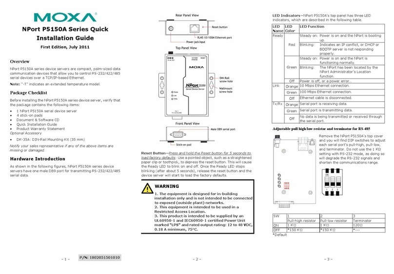
5. Pull High/low Resistors & Terminators Setting for
the RS-485 Port
DIP switches on the bottom of NPort
S8455I-MM-SC are used to set the pull
high/low resistor values for each serial port.
1 2 3 4 3&4
SW Pull High Pull Low Terminator Terminator Terminator
ON 1 KΩ1 KΩ120 Ω100 Ω55 Ω
Default OFF 150 KΩ150 KΩ--- --- ---
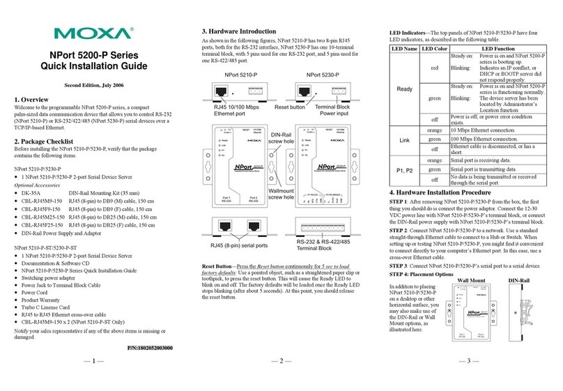
6. Turbo Ring DIP Switch Settings
21
------
MASTER
COUPLER
TURBO
RING
43
The default setting for each DIP switch is OFF. The
following table explains the effect of setting the DIP
switch to the ON position.
Turbo Ring Settings
DIP1 DIP2 DIP3 DIP4
DIP --- Ring Master Ring Coupling
port DIP 1, 2, 3
ON --- Enable Enable Activates
Default OFF --- Disable Disable Disabled
Turbo Ring 2 Settings
DIP1 DIP2 DIP3 DIP4
DIP Ring Coupling Ring
Master Ring
Coupling port DIP 1, 2, 3
ON Backup port
Enable Enable Enable Activates
Default OFF Primary port
Enable Disable Disable Disabled.
7. Software Installation Information
The Document & Software CD contains the User’s Manual,Driver,SNMP
MIB, NPort Search Utility. Insert the CD and follow the on-screen
instructions. Please refer to the User’s Manual for additional details on
using the NPort Search Utility and Driver, SNMP MIB.
8. PinAssignments and Cable Wiring
DB9 Male Port Pinouts
DB9 Male
15
69
Pin RS-232 RS-422/
4-wire RS-485 2-wire
RS-485
1 DCD TxD-(A) ---
2 RxD TxD+(B) ---
3 TxD RxD+(B) Data+(B)
4 DTR RxD-(A) Data-(A)
5 GND GND GND
6 DSR --- ---
7 RTS --- ---
8 CTS --- ---
9 --- --- ---
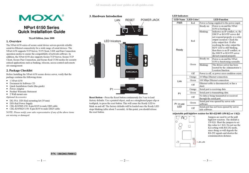
Wiring the Relay Contact
The NPort S8455I-MM-SC has two sets of relay outputs—relay 1 and
relay 2. Each relay contact consists of two contacts of the terminal block
on the NPort S8455I-MM-SC’s top panel. Refer to the next section for
detailed instructions on how to connect the wires to the terminal block
connector, and how to attach the terminal block connector to the terminal
block receptor. The meaning of the two contacts used to connect the relay
contacts is illustrated below.
The fault circuit will open if
1. A relay warning event is triggered, OR
2. The NPort S8455I-MM-SC is the Master of
this Turbo Ring, and the Turbo Ring is
broken, OR
3. Start-up fails.
If none of these three conditions is met, the fault
circuit will remain closed.
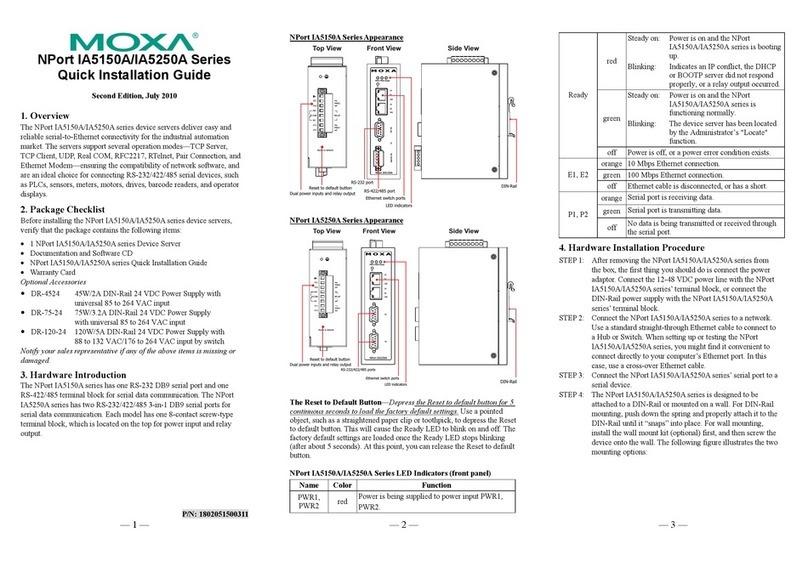
Wiring the Digital Inputs
The NPort S8455I-MM-SC unit has two sets of digital inputs, DI 1 and
DI 2. Each DI consists of two contacts of the 6-pin terminal block
connector on the NPort S8455I-MM-SC’s top panel. The remaining
contacts are used for the NPort S8455I-MM-SC’s two DC inputs. Top
and front views of one of the terminal block connectors are shown below.
Take the following steps to wire the digital inputs:
STEP 1: Insert the negative (ground) or positive DI
wires into the terminals.
STEP 2: To keep the DI wires from getting loose,
use a small flat-blade screwdriver to tighten the
wire-clamp screws on the front of the terminal
block connector.
STEP 3: Insert the plastic terminal block connector
prongs into the terminal block receptor, which is
located on the NPort 8455I-MM-SC’s top panel.
Wiring the Redundant Power Inputs
The NPort S8455I-MM-SC unit has two sets of power inputs—power
input 1 and power input 2. The top two contacts and the bottom two
contacts of the 6-pin terminal block connector on the top panel are used
for the NPort S8455I-MM-SC’s two power inputs. Top and front views of
one of the terminal block connectors are shown below.
Take the following steps to wire the redundant power inputs:
STEP 1: Insert the negative/positive DC wires into the V-/V+ terminals.
STEP 2: To keep the DC wires from pulling loose, use a small flat-blade
screwdriver to tighten the wire-clamp screws on the front of the terminal
block connector.
STEP 3: Insert the plastic terminal block connector prongs into the
terminal block receptor, which is located on the NPort S8455I-MM-SC’s
top panel.
9. Environmental Specifications
Power requirements 12 to 48 VDC, 887 mA at 12V (max.)
Operating temp. 0 to 55◦C (32 to 131◦F)
Operating humidity 5 to 95% RH
Dimensions (W×D×H) 73 × 125 × 144 mm
2.87 × 4.92 × 5.64 in
Regulatory approvals
EMC: CE (EN55022 Class A, EN55024),
FCC Part 15 Subpart B Class A
Safety: UL-508, UL (UL60950-1), LVD (EN60950-1)
ESD: IEC 61000-4-2, Level 4
EFT: IEC 61000-4-4, Level 4
Surge: Serial Port - IEC 61000-4-5 Level 1
Ethernet Port - IEC 61000-4-5 Level 2
Power Line - IEC 61000-4-5 Level 3
Click here for online support:
www.moxa.com/support
The Americas: +1-714-528-6777 (toll-free: 1-888-669-2872)
Europe: +49-89-3 70 03 99-0
Asia-Pacific: +886-2-8919-1230
China: +86-21-5258-9955 (toll-free: 800-820-5036)
©2009 Moxa Inc. All rights reserved.
Reproduction without permission is prohibited.
