MPS EVKT-1203 User manual

HR1200 Evaluation Kit User Guide Rev 1.0 MonolithicPower.com 0
5/7/2019 MPS Proprietary Information. Patent Protected. Unauthorized Photocopy and Duplication Prohibited.
© 2019 MPS. All Rights Reserved.
User Guide
HR1203 Evaluation Kit (EVKT-1203)
User Guide
HR1203 Evaluation Kit (EVKT-1203)
HR1203 Evaluation Kit User Guide Rev 1.0 MonolithicPower.com 1
5/7/2019 MPS Proprietary Information. Patent Protected. Unauthorized Photocopy and Duplication Prohibited.
© 2019 MPS. All Rights Reserved.
Table of Contents
Overview...................................................................................................................................................2
Introduction ...........................................................................................................................................2
Kit Contents...........................................................................................................................................2
Features and Benefits...........................................................................................................................3
Kit Specifications...................................................................................................................................3
Section 1. Hardware Specifications..........................................................................................................4
1.1 Personal Computer Requirements..................................................................................................4
1.2 EVB Specifications..........................................................................................................................4
1.3 EVHR1203 PMBUS Kit Specifications............................................................................................4
1.4 USB Isolator Specifications.............................................................................................................5
Section 2. Software Requirements ...........................................................................................................6
2.1 Software Installation Procedure ......................................................................................................6
Section 3. Evaluation Kit Test Set-Up.......................................................................................................7
3.1 Hardware Set-Up.............................................................................................................................7
3.2 Powering Up the EVB......................................................................................................................7
3.3 Software Set-Up and Device Programming Instructions.................................................................8
3.5 Troubleshooting Tips.....................................................................................................................16
Section 4. Ordering Information..............................................................................................................18
User Guide
HR1203 Evaluation Kit (EVKT-1203)
HR1203 Evaluation Kit User Guide Rev 1.0 MonolithicPower.com 2
5/7/2019 MPS Proprietary Information. Patent Protected. Unauthorized Photocopy and Duplication Prohibited.
© 2019 MPS. All Rights Reserved.
Overview
Introduction
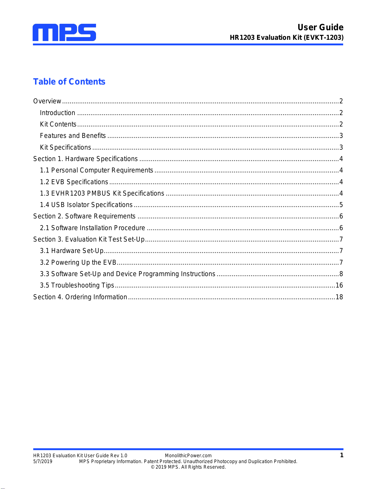
The EVKT-1203 is an evaluation kit for the HR1203. A 240W evaluation board is designed with a high
power factor (PF) at light load (>0.95 at 20% load). The unique benefits for the board are its very low no-
load power consumption (<150mW) and very high light-load efficiency (>90% at 10% load), which meets
Energy using Product Directive (EuP) Lot 6 and Code of Conduct Version 5 Tier 2.
These features are suitable for applications including PCs, ATX power, notebook adapters, and gaming
and TV power supplies. With the programming communication interface and GUI software, circuit
configurations of the digital PFC part can be easily customized, greatly increasing design flexibility.
Kit Contents
EVKT-1203-TSSOP kit contents (items below can be ordered separately):
#
Part Number
Item
Quantity
1
EVHR1203-M-02A
Evaluation board (IC in TSSOP-28)
1
2
EVHR1203 PMBUS Kit-01A
USB to I2C programming communication interface
1
USB cable
1
Ribbon cable
1
3
T-USB Isolation Block-00A
USB isolator
1
EVKT-1203-SOIC kit contents (items below can be ordered separately):
#
Part Number
Item
Quantity
1
EVHR1203-Y-00A *
Evaluation board (IC in SOIC-28)
1
2
EVHR1203 PMBUS Kit-01A
USB to I2C programming communication interface
1
USB cable
1
Ribbon cable
1
3
T-USB Isolation Block-00A
USB isolator
1
EVHR1203-Y-00A *: can be commonly used for HR1204 by swapping the IC.
Figure 1: EVKT-1203 Evaluation Kit Set-Up
User Guide
HR1203 Evaluation Kit (EVKT-1203)
HR1203 Evaluation Kit User Guide Rev 1.0 MonolithicPower.com 3
5/7/2019 MPS Proprietary Information. Patent Protected. Unauthorized Photocopy and Duplication Prohibited.
© 2019 MPS. All Rights Reserved.
Features and Benefits
The evaluation board is mainly designed to demonstrate the capabilities of MPS’s highly integrated
HR1203 controller. The HR1203 is a high-performance combo controller that integrates an advanced
digital PFC controller and a half-bridge LLC resonant controller.
The PFC part employs a patented average current control scheme, and can switch automatically between
continuous conduction mode (CCM) and discontinuous conduction mode (DCM), according to the
instantaneous condition of the input voltage and output load. With this feature, the IC exhibits excellent
efficiency and high PF at light load. The LLC part implements an adaptive dead-time adjustment (ADTA)
function to guarantee zero-voltage switching (ZVS) in different load conditions. In addition, a high-voltage
(HV) current source is integrated internally for start-up and X-cap discharge, which helps reduce power
consumption at no load.
Use the USB isolator when in online mode with AC input.
Make sure both the communication interface and EVB board are reset every time before
restarting the GUI.
Kit Specifications
Features
Specification
Operating Input Voltage
90Vac to 265Vac
Operating Output Voltage
12V
Operating Output Current
20A
Operating Systems Supported
Windows XP, 7, and later
System Requirements
Minimum 21.7MB free
GUI Software
MPS programmable power GUI v3.3
EVB Size (LxW)
17.4cmx10.5cm
User Guide
HR1203 Evaluation Kit (EVKT-1203)
HR1203 Evaluation Kit User Guide Rev 1.0 MonolithicPower.com 4
5/7/2019 MPS Proprietary Information. Patent Protected. Unauthorized Photocopy and Duplication Prohibited.
© 2019 MPS. All Rights Reserved.
Section 1. Hardware Specifications
1.1 Personal Computer Requirements
The following must be met to use the EVKT-1203:
Operating system of Windows XP, 7, or later
Net Framework 4.0
PC with a minimum of one available USB port
At least 21.7MB of free space
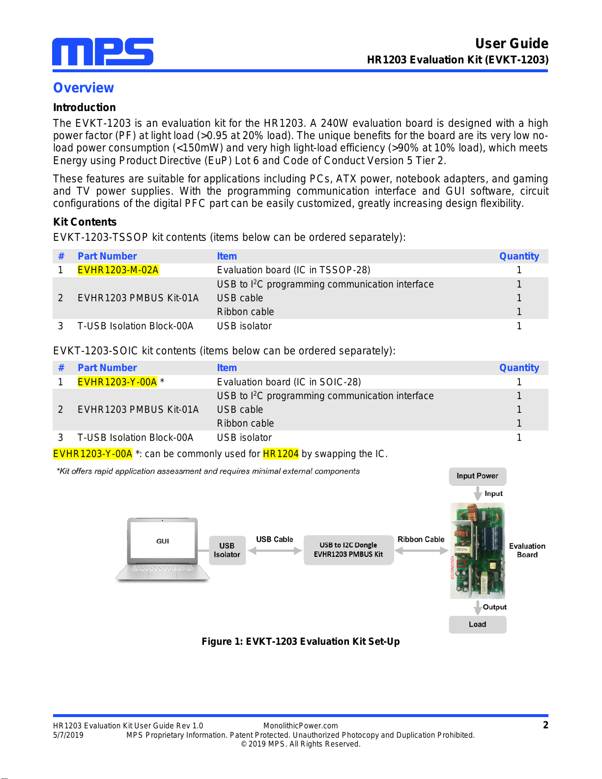
1.2 EVB Specifications
The EVHR1203-M-02A and EVHR1203-Y-00A are evaluation boards for the HR1203, and are available
in TSSOP-28 and SOIC-28 packages, respectively. For more information, refer to the EVB datasheet.
Figure 2: Evaluation Board
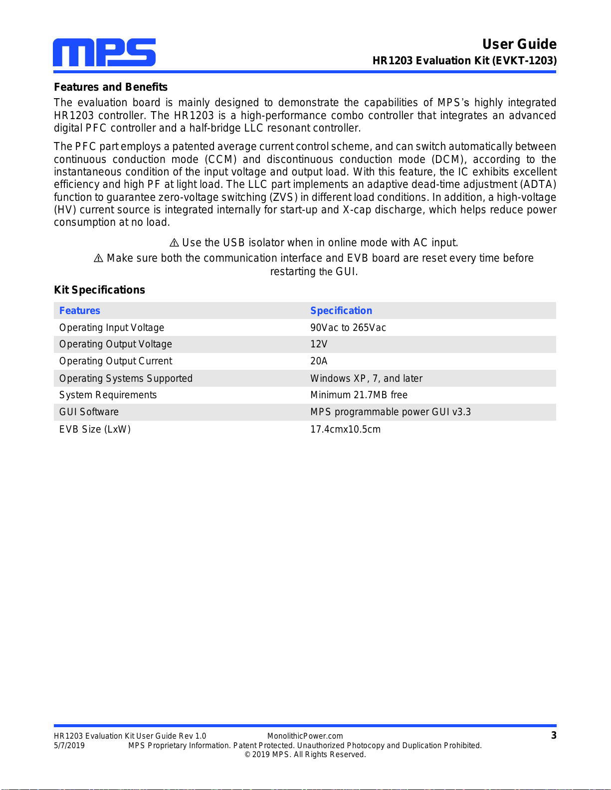
1.3 EVHR1203 PMBUS Kit Specifications
The EVHR1203 PMBUS Kit-01A refers to the USB to I2C programming communication interface, which
connects the EVB and the PC. It provides PMBus capabilities. Together with the MPS GUI, it provides a
quick and easy way to evaluate the performance of the HR1203. For more details, refer to the AN103-
User Guideline_HR1203 I2C Kit and GUI.
Figure 3: EVHR1203 PMBUS Kit-01A Communication Interface
Feature
Specification
Input AC Voltage
90Vac to 265Vac
Output Voltage
12V
Output Current
20A
EVB Size (LxW)
17.4cmx10.5cm
User Guide
HR1203 Evaluation Kit (EVKT-1203)
HR1203 Evaluation Kit User Guide Rev 1.0 MonolithicPower.com 5
5/7/2019 MPS Proprietary Information. Patent Protected. Unauthorized Photocopy and Duplication Prohibited.
© 2019 MPS. All Rights Reserved.
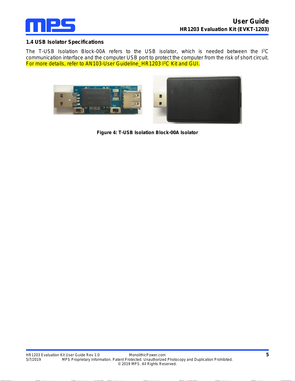
1.4 USB Isolator Specifications
The T-USB Isolation Block-00A refers to the USB isolator, which is needed between the I2C
communication interface and the computer USB port to protect the computer from the risk of short circuit.
For more details, refer to AN103-User Guideline_HR1203 I2C Kit and GUI.
Figure 4: T-USB Isolation Block-00A Isolator
User Guide
HR1203 Evaluation Kit (EVKT-1203)
HR1203 Evaluation Kit User Guide Rev 1.0 MonolithicPower.com 6
5/7/2019 MPS Proprietary Information. Patent Protected. Unauthorized Photocopy and Duplication Prohibited.
© 2019 MPS. All Rights Reserved.
Section 2. Software Requirements
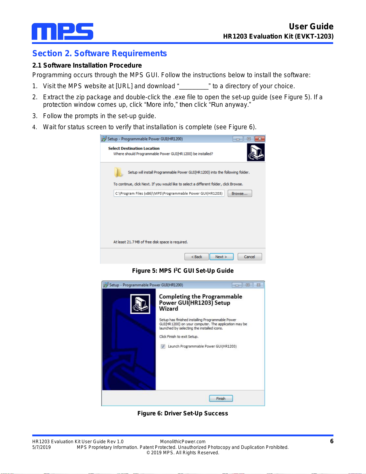
2.1 Software Installation Procedure
Programming occurs through the MPS GUI. Follow the instructions below to install the software:
1. Visit the MPS website at [URL] and download “________” to a directory of your choice.
2. Extract the zip package and double-click the .exe file to open the set-up guide (see Figure 5). If a
protection window comes up, click “More info,” then click “Run anyway.”
3. Follow the prompts in the set-up guide.
4. Wait for status screen to verify that installation is complete (see Figure 6).
Figure 5: MPS I2C GUI Set-Up Guide
Figure 6: Driver Set-Up Success
User Guide
HR1203 Evaluation Kit (EVKT-1203)
HR1203 Evaluation Kit User Guide Rev 1.0 MonolithicPower.com 7
5/7/2019 MPS Proprietary Information. Patent Protected. Unauthorized Photocopy and Duplication Prohibited.
© 2019 MPS. All Rights Reserved.
Section 3. Evaluation Kit Test Set-Up
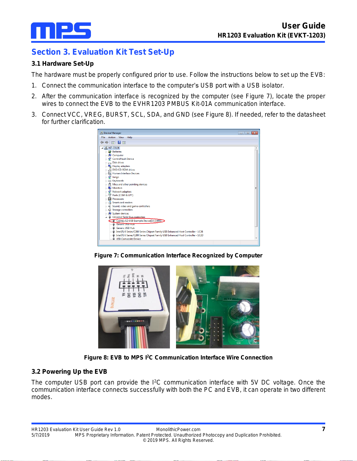
3.1 Hardware Set-Up
The hardware must be properly configured prior to use. Follow the instructions below to set up the EVB:
1. Connect the communication interface to the computer’s USB port with a USB isolator.
2. After the communication interface is recognized by the computer (see Figure 7), locate the proper
wires to connect the EVB to the EVHR1203 PMBUS Kit-01A communication interface.
3. Connect VCC, VREG, BURST, SCL, SDA, and GND (see Figure 8). If needed, refer to the datasheet
for further clarification.
Figure 7: Communication Interface Recognized by Computer
Figure 8: EVB to MPS I2C Communication Interface Wire Connection
3.2 Powering Up the EVB
The computer USB port can provide the I2C communication interface with 5V DC voltage. Once the
communication interface connects successfully with both the PC and EVB, it can operate in two different
modes.
User Guide
HR1203 Evaluation Kit (EVKT-1203)
HR1203 Evaluation Kit User Guide Rev 1.0 MonolithicPower.com 8
5/7/2019 MPS Proprietary Information. Patent Protected. Unauthorized Photocopy and Duplication Prohibited.
© 2019 MPS. All Rights Reserved.
Offline Mode: No need to power up the EVB. The communication interface detects that VCC is lower
than 8V upon connection. It provides the power supply to VCC and VREG, and sends a predetermined
signal to BURST. The IC then enters a dedicated test mode for programming.
Online Mode: Supply AC input to the EVB. The communication interface detects that VCC is higher than
8V upon connection. It only provides the power supply to VCC. Then the IC works in normal operation.
To complete this process, follow the steps below:
1. Connect the positive and negative terminals of the load to the VOUT and GND pins of the EVB,
respectively.
2. Preset the power supply output between 90Vac and 265Vac.
3. Connect the positive and negative terminals of the power supply output to the VIN and GND pins of
the EVB, respectively.
4. Turn the power supply on.
3.3 Software Set-Up and Device Programming Instructions
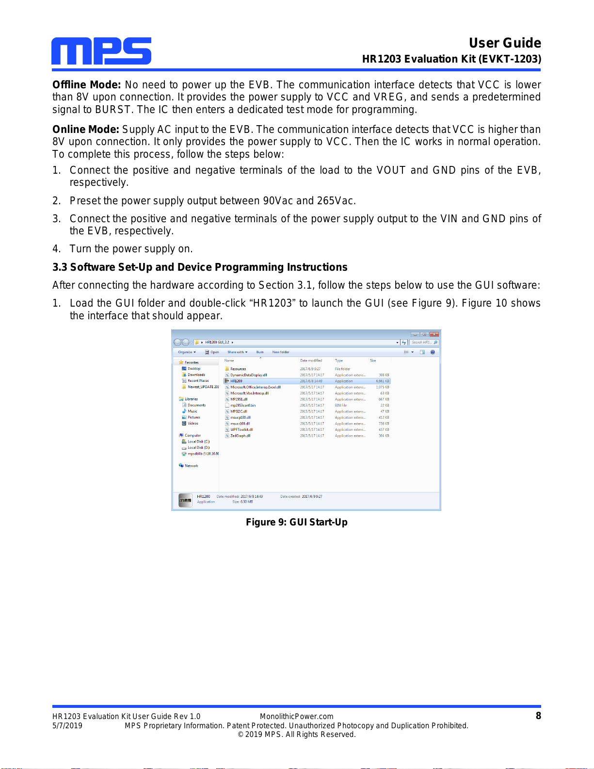
After connecting the hardware according to Section 3.1, follow the steps below to use the GUI software:
1. Load the GUI folder and double-click “HR1203”to launch the GUI (see Figure 9). Figure 10 shows
the interface that should appear.
Figure 9: GUI Start-Up
User Guide
HR1203 Evaluation Kit (EVKT-1203)
HR1203 Evaluation Kit User Guide Rev 1.0 MonolithicPower.com 9
5/7/2019 MPS Proprietary Information. Patent Protected. Unauthorized Photocopy and Duplication Prohibited.
© 2019 MPS. All Rights Reserved.
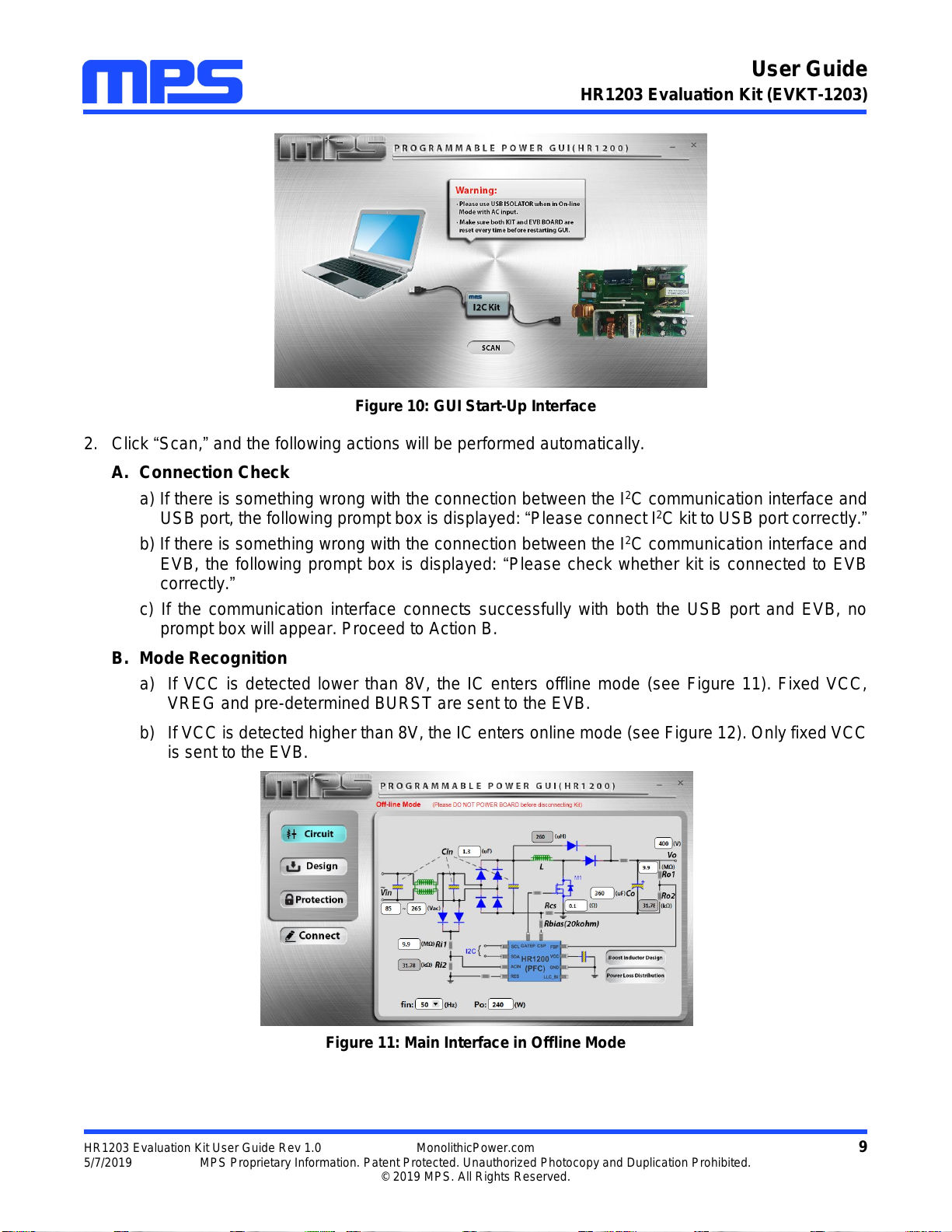
Figure 10: GUI Start-Up Interface
2. Click “Scan,”and the following actions will be performed automatically.
A. Connection Check
a) If there is something wrong with the connection between the I2C communication interface and
USB port, the following prompt box is displayed: “Please connect I2C kit to USB port correctly.”
b) If there is something wrong with the connection between the I2C communication interface and
EVB, the following prompt box is displayed: “Please check whether kit is connected to EVB
correctly.”
c) If the communication interface connects successfully with both the USB port and EVB, no
prompt box will appear. Proceed to Action B.
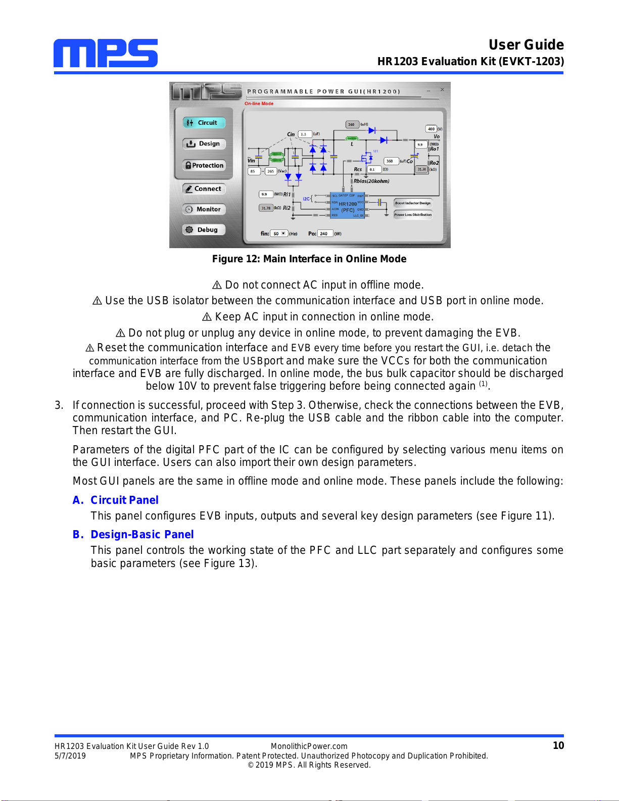
B. Mode Recognition
a) If VCC is detected lower than 8V, the IC enters offline mode (see Figure 11). Fixed VCC,
VREG and pre-determined BURST are sent to the EVB.
b) If VCC is detected higher than 8V, the IC enters online mode (see Figure 12). Only fixed VCC
is sent to the EVB.
Figure 11: Main Interface in Offline Mode
User Guide
HR1203 Evaluation Kit (EVKT-1203)
HR1203 Evaluation Kit User Guide Rev 1.0 MonolithicPower.com 10
5/7/2019 MPS Proprietary Information. Patent Protected. Unauthorized Photocopy and Duplication Prohibited.
© 2019 MPS. All Rights Reserved.
Figure 12: Main Interface in Online Mode
Do not connect AC input in offline mode.
Use the USB isolator between the communication interface and USB port in online mode.
Keep AC input in connection in online mode.
Do not plug or unplug any device in online mode, to prevent damaging the EVB.
Reset the communication interface and EVB every time before you restart the GUI, i.e. detach the
communication interface from the USBport and make sure the VCCs for both the communication
interface and EVB are fully discharged. In online mode, the bus bulk capacitor should be discharged
below 10V to prevent false triggering before being connected again (1).
3. If connection is successful, proceed with Step 3. Otherwise, check the connections between the EVB,
communication interface, and PC. Re-plug the USB cable and the ribbon cable into the computer.
Then restart the GUI.
Parameters of the digital PFC part of the IC can be configured by selecting various menu items on
the GUI interface. Users can also import their own design parameters.
Most GUI panels are the same in offline mode and online mode. These panels include the following:
A. Circuit Panel
This panel configures EVB inputs, outputs and several key design parameters (see Figure 11).
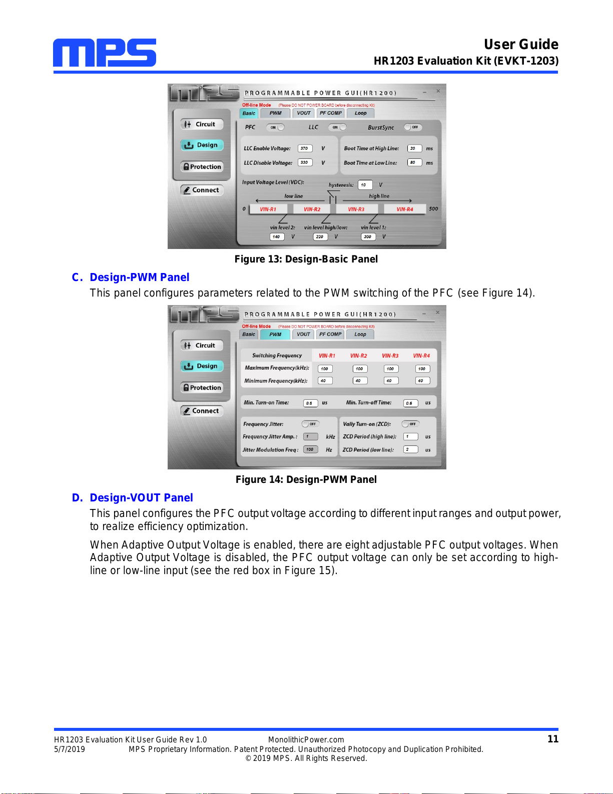
B. Design-Basic Panel
This panel controls the working state of the PFC and LLC part separately and configures some
basic parameters (see Figure 13).
User Guide
HR1203 Evaluation Kit (EVKT-1203)
HR1203 Evaluation Kit User Guide Rev 1.0 MonolithicPower.com 11
5/7/2019 MPS Proprietary Information. Patent Protected. Unauthorized Photocopy and Duplication Prohibited.
© 2019 MPS. All Rights Reserved.
Figure 13: Design-Basic Panel
C. Design-PWM Panel
This panel configures parameters related to the PWM switching of the PFC (see Figure 14).
Figure 14: Design-PWM Panel
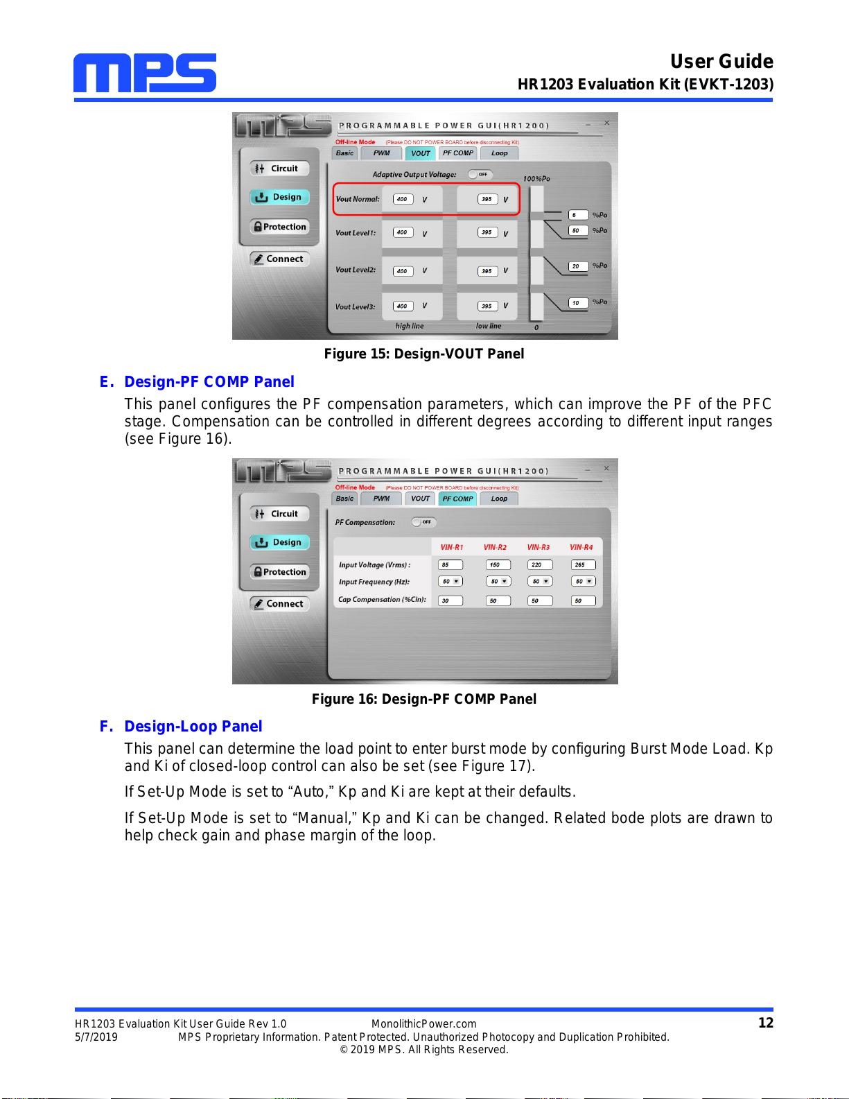
D. Design-VOUT Panel
This panel configures the PFC output voltage according to different input ranges and output power,
to realize efficiency optimization.
When Adaptive Output Voltage is enabled, there are eight adjustable PFC output voltages. When
Adaptive Output Voltage is disabled, the PFC output voltage can only be set according to high-
line or low-line input (see the red box in Figure 15).
User Guide
HR1203 Evaluation Kit (EVKT-1203)
HR1203 Evaluation Kit User Guide Rev 1.0 MonolithicPower.com 12
5/7/2019 MPS Proprietary Information. Patent Protected. Unauthorized Photocopy and Duplication Prohibited.
© 2019 MPS. All Rights Reserved.
Figure 15: Design-VOUT Panel
E. Design-PF COMP Panel
This panel configures the PF compensation parameters, which can improve the PF of the PFC
stage. Compensation can be controlled in different degrees according to different input ranges
(see Figure 16).
Figure 16: Design-PF COMP Panel
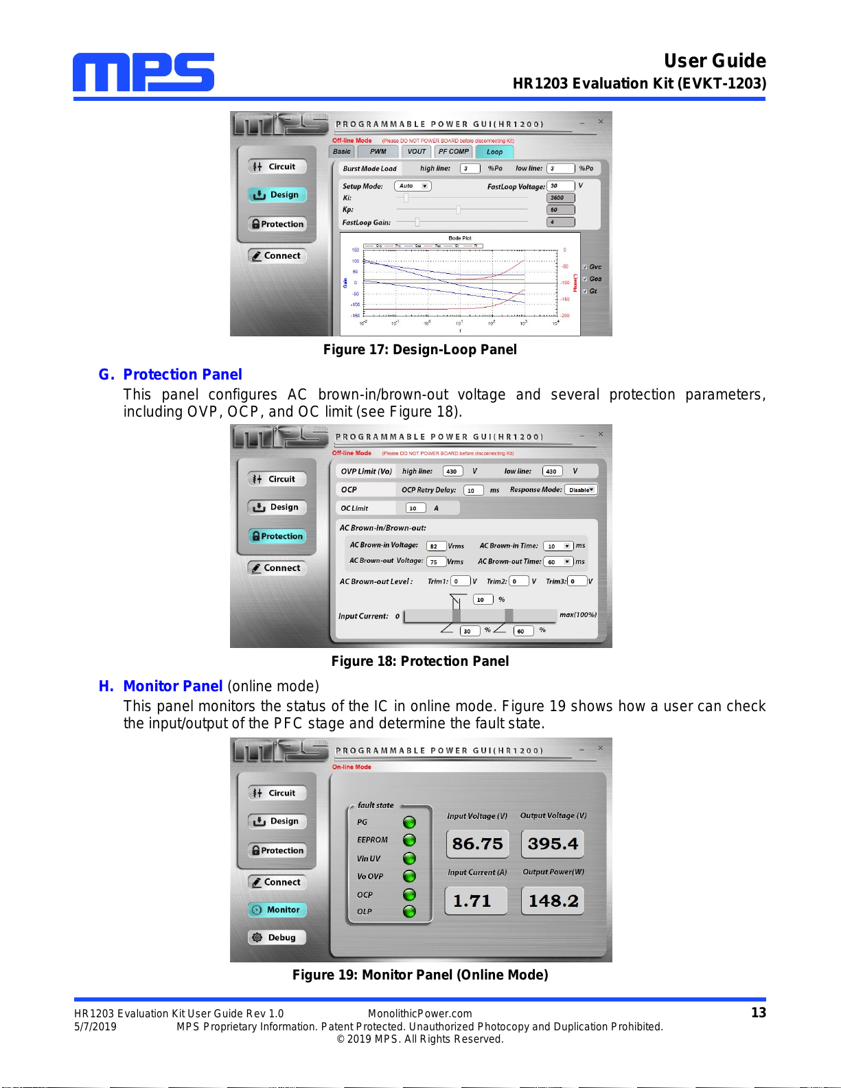
F. Design-Loop Panel
This panel can determine the load point to enter burst mode by configuring Burst Mode Load. Kp
and Ki of closed-loop control can also be set (see Figure 17).
If Set-Up Mode is set to “Auto,”Kp and Ki are kept at their defaults.
If Set-Up Mode is set to “Manual,”Kp and Ki can be changed. Related bode plots are drawn to
help check gain and phase margin of the loop.
User Guide
HR1203 Evaluation Kit (EVKT-1203)
HR1203 Evaluation Kit User Guide Rev 1.0 MonolithicPower.com 13
5/7/2019 MPS Proprietary Information. Patent Protected. Unauthorized Photocopy and Duplication Prohibited.
© 2019 MPS. All Rights Reserved.
Figure 17: Design-Loop Panel
G. Protection Panel
This panel configures AC brown-in/brown-out voltage and several protection parameters,
including OVP, OCP, and OC limit (see Figure 18).
Figure 18: Protection Panel
H. Monitor Panel (online mode)
This panel monitors the status of the IC in online mode. Figure 19 shows how a user can check
the input/output of the PFC stage and determine the fault state.
Figure 19: Monitor Panel (Online Mode)
User Guide
HR1203 Evaluation Kit (EVKT-1203)
HR1203 Evaluation Kit User Guide Rev 1.0 MonolithicPower.com 14
5/7/2019 MPS Proprietary Information. Patent Protected. Unauthorized Photocopy and Duplication Prohibited.
© 2019 MPS. All Rights Reserved.
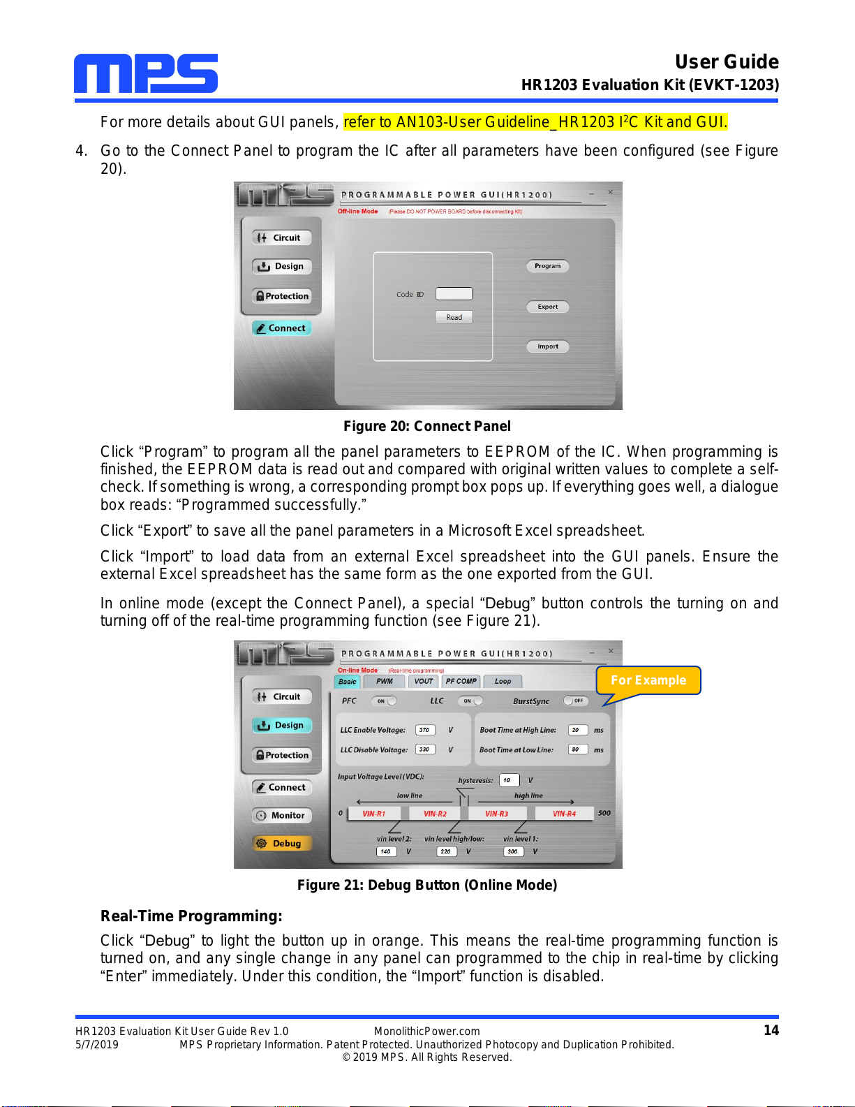
For more details about GUI panels, refer to AN103-User Guideline_HR1203 I2C Kit and GUI.
4. Go to the Connect Panel to program the IC after all parameters have been configured (see Figure
20).
Figure 20: Connect Panel
Click “Program”to program all the panel parameters to EEPROM of the IC. When programming is
finished, the EEPROM data is read out and compared with original written values to complete a self-
check. If something is wrong, a corresponding prompt box pops up. If everything goes well, a dialogue
box reads: “Programmed successfully.”
Click “Export”to save all the panel parameters in a Microsoft Excel spreadsheet.
Click “Import”to load data from an external Excel spreadsheet into the GUI panels. Ensure the
external Excel spreadsheet has the same form as the one exported from the GUI.
In online mode (except the Connect Panel), a special “Debug” button controls the turning on and
turning off of the real-time programming function (see Figure 21).
Figure 21: Debug Button (Online Mode)
Real-Time Programming:
Click “Debug” to light the button up in orange. This means the real-time programming function is
turned on, and any single change in any panel can programmed to the chip in real-time by clicking
“Enter”immediately. Under this condition, the “Import”function is disabled.
For Example

User Guide
HR1203 Evaluation Kit (EVKT-1203)
HR1203 Evaluation Kit User Guide Rev 1.0 MonolithicPower.com 15
5/7/2019 MPS Proprietary Information. Patent Protected. Unauthorized Photocopy and Duplication Prohibited.
© 2019 MPS. All Rights Reserved.
Click “Debug” again to turn off the real-time programming function. The color of the button should
return to gray.
Real-time programming is a risky programming mode. If you make a change in a
data box and click “Enter,”then all panel parameters, not only the changed one, will be
programmed to the chip. Therefore it is strongly recommended to repeatedly confirm panel
parameters before clicking “Enter.”
Do not forget to click “Enter”in real-time programming. Otherwise, the data
change in GUI will not be updated to the chip.
5. Close the GUI. Since the panel parameters restore default values every time restarting the GUI, it is
better to save current panel parameters before exiting.
6. If in online mode, disconnect AC input then reset the communication interface and EVB (1).
If in offline mode, reset the communication interface and EVB (1).
Note:
1) To reset communication interface: Ensure that the VCC of the communication interface is fully discharged.
To reset EVB: For offline mode, ensure that the EBV VCC is fully discharged. For online mode, ensure that the EVB VCC is fully
discharged and the bus bulk capacitor is discharged below 10V.
VCC fully discharged: VCC discharged below 2V. The discharge time may vary with different application designs.
User Guide
HR1203 Evaluation Kit (EVKT-1203)
HR1203 Evaluation Kit User Guide Rev 1.0 MonolithicPower.com 16
5/7/2019 MPS Proprietary Information. Patent Protected. Unauthorized Photocopy and Duplication Prohibited.
© 2019 MPS. All Rights Reserved.
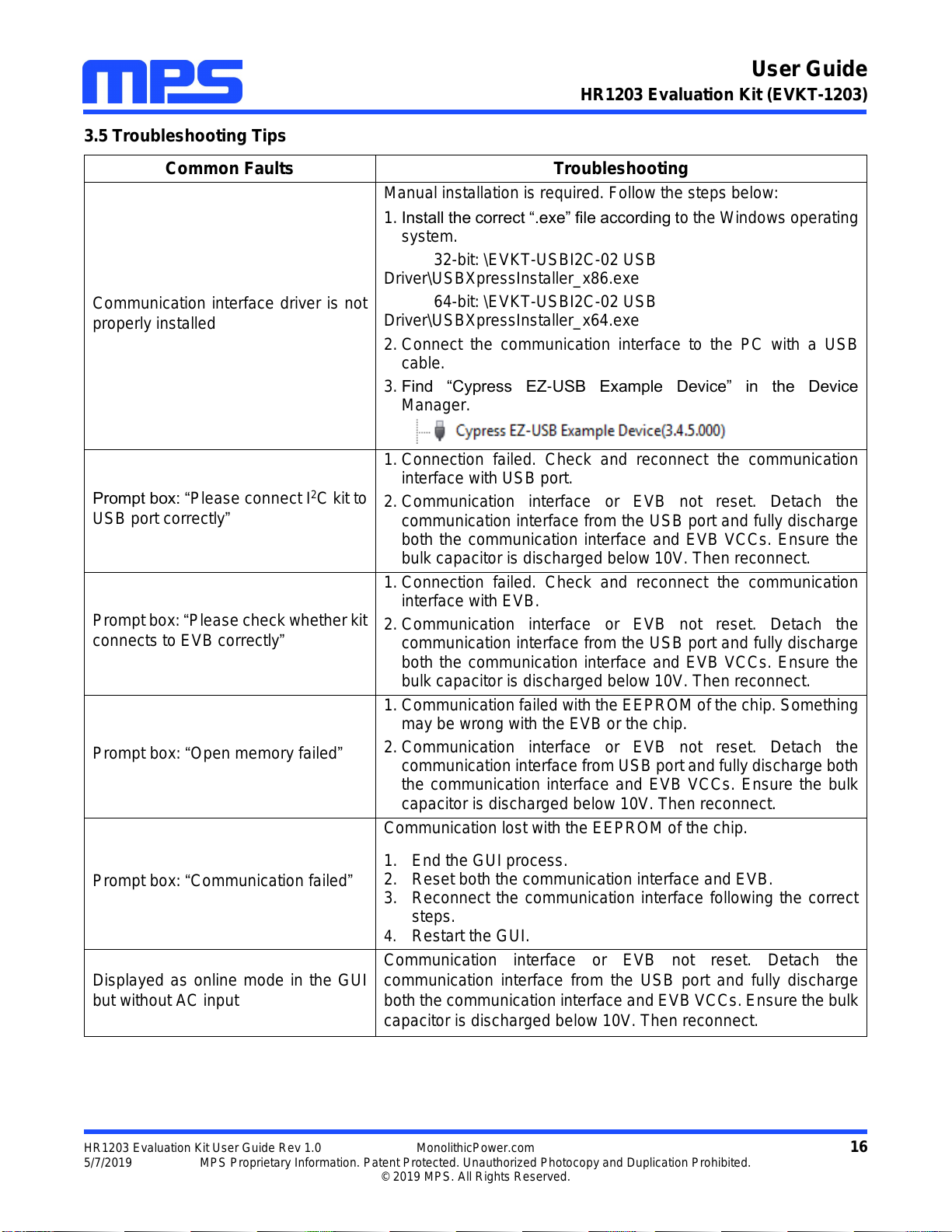
3.5 Troubleshooting Tips
Common Faults
Troubleshooting
Communication interface driver is not
properly installed
Manual installation is required. Follow the steps below:
1. Install the correct “.exe” file according to the Windows operating
system.
32-bit: \EVKT-USBI2C-02 USB
Driver\USBXpressInstaller_x86.exe
64-bit: \EVKT-USBI2C-02 USB
Driver\USBXpressInstaller_x64.exe
2. Connect the communication interface to the PC with a USB
cable.
3. Find “Cypress EZ-USB Example Device” in the Device
Manager.
Prompt box: “Please connect I2C kit to
USB port correctly”
1. Connection failed. Check and reconnect the communication
interface with USB port.
2. Communication interface or EVB not reset. Detach the
communication interface from the USB port and fully discharge
both the communication interface and EVB VCCs. Ensure the
bulk capacitor is discharged below 10V. Then reconnect.
Prompt box: “Please check whether kit
connects to EVB correctly”
1. Connection failed. Check and reconnect the communication
interface with EVB.
2. Communication interface or EVB not reset. Detach the
communication interface from the USB port and fully discharge
both the communication interface and EVB VCCs. Ensure the
bulk capacitor is discharged below 10V. Then reconnect.
Prompt box: “Open memory failed”
1. Communication failed with the EEPROM of the chip. Something
may be wrong with the EVB or the chip.
2. Communication interface or EVB not reset. Detach the
communication interface from USB port and fully discharge both
the communication interface and EVB VCCs. Ensure the bulk
capacitor is discharged below 10V. Then reconnect.
Prompt box: “Communication failed”
Communication lost with the EEPROM of the chip.
1. End the GUI process.
2. Reset both the communication interface and EVB.
3. Reconnect the communication interface following the correct
steps.
4. Restart the GUI.
Displayed as online mode in the GUI
but without AC input
Communication interface or EVB not reset. Detach the
communication interface from the USB port and fully discharge
both the communication interface and EVB VCCs. Ensure the bulk
capacitor is discharged below 10V. Then reconnect.

User Guide
HR1203 Evaluation Kit (EVKT-1203)
HR1203 Evaluation Kit User Guide Rev 1.0 MonolithicPower.com 17
5/7/2019 MPS Proprietary Information. Patent Protected. Unauthorized Photocopy and Duplication Prohibited.
© 2019 MPS. All Rights Reserved.
Communication interface not
recognized by the computer
1. Communication interface or EVB not reset. Detach the
communication interface from the USB port and fully discharge
both the communication interface and EVB VCCs. Ensure the
bulk capacitor is discharged below 10V. Then reconnect.
2. Driver installation problems. Re-install.
3. USB port damaged. Try another port.
4. Restart computer.
5. Communication interface damaged. Try another communication
interface.
GUI or computer crash
1. End the GUI process.
2. Reset both the communication interface and EVB.
3. Reconnect the communication interface following the correct
steps.
4. Restart the GUI.
Prompt box: “Import Error”
1. Nonstandard form of external Excel spreadsheet.
2. Microsoft Excel needs to be updated.
Prompt box: “Export Error”
Microsoft Excel needs to be updated.
User Guide
HR1203 Evaluation Kit (EVKT-1203)
HR1203 Evaluation Kit User Guide Rev 1.0 MonolithicPower.com 18
5/7/2019 MPS Proprietary Information. Patent Protected. Unauthorized Photocopy and Duplication Prohibited.
© 2019 MPS. All Rights Reserved.
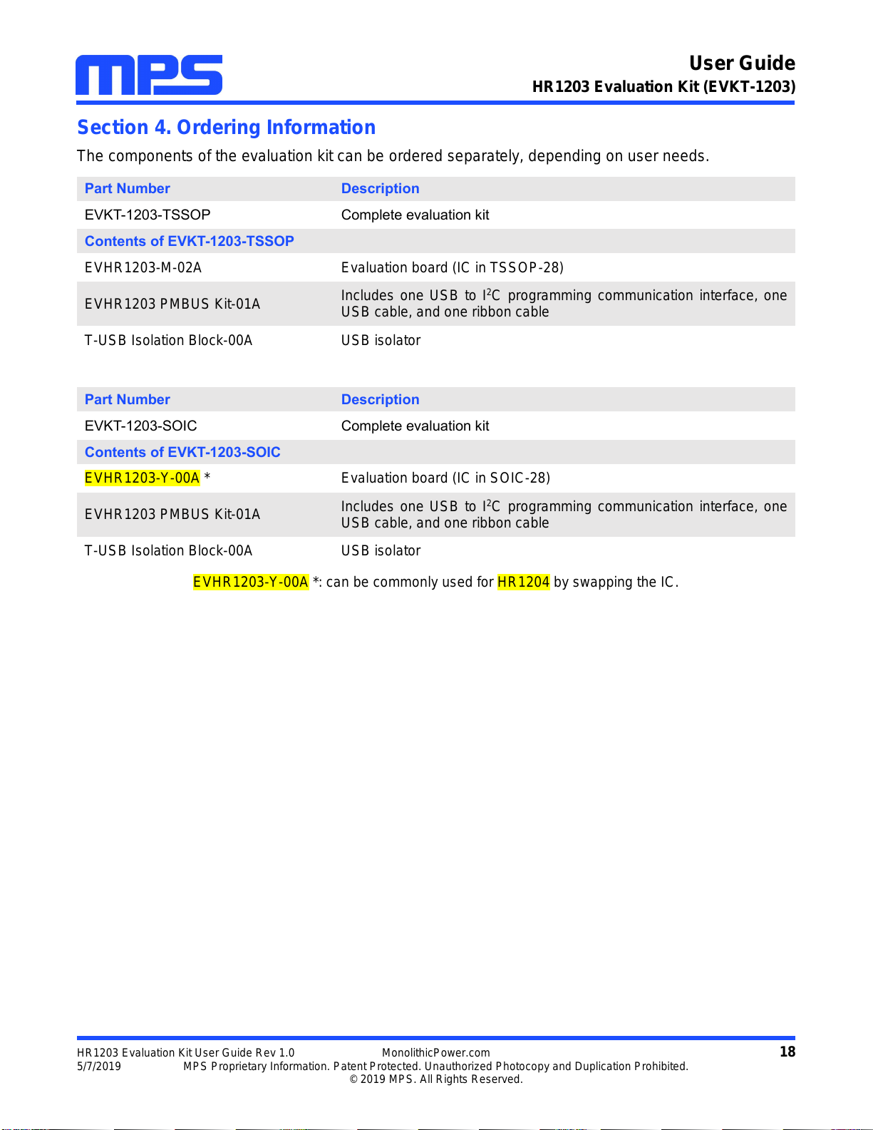
Section 4. Ordering Information
The components of the evaluation kit can be ordered separately, depending on user needs.
Part Number
Description
EVKT-1203-TSSOP
Complete evaluation kit
Contents of EVKT-1203-TSSOP
EVHR1203-M-02A
Evaluation board (IC in TSSOP-28)
EVHR1203 PMBUS Kit-01A
Includes one USB to I2C programming communication interface, one
USB cable, and one ribbon cable
T-USB Isolation Block-00A
USB isolator
Part Number
Description
EVKT-1203-SOIC
Complete evaluation kit
Contents of EVKT-1203-SOIC
EVHR1203-Y-00A *
Evaluation board (IC in SOIC-28)
EVHR1203 PMBUS Kit-01A
Includes one USB to I2C programming communication interface, one
USB cable, and one ribbon cable
T-USB Isolation Block-00A
USB isolator
EVHR1203-Y-00A *: can be commonly used for HR1204 by swapping the IC.
This manual suits for next models
1
Table of contents
Other MPS Motherboard manuals

MPS
MPS MagAlpha EVMA Q-00A Series Operating instructions

MPS
MPS EVQ4488-U-00B User manual

MPS
MPS EVKT-MP8862 User manual

MPS
MPS EV1518DG-00A User manual

MPS
MPS EVKT6515 User manual

MPS
MPS EV2690-R-00A User manual

MPS
MPS EVKT-MACOM User manual

MPS
MPS EV26059DQ-00B User manual

MPS
MPS MP2672 User manual

MPS
MPS EV2759-Q-00A User manual

MPS
MPS mEZDPD4506A User manual

MPS
MPS EV5480-C-00A User manual

MPS
MPS EV0035 User manual

MPS
MPS EV6539B-F-00A User manual

MPS
MPS EVQ6541A-QK-00A User manual

MPS
MPS EV6532-R-01A User manual

MPS
MPS EVBL2166-D-00A User manual

MPS
MPS EV2483DQ-00C User manual

MPS
MPS MP2760 User manual

MPS
MPS EV5920-5048-V-00A User manual


