SPECIAL LIGHTS WIRING
If you loco has ditch lights or mars light/strobe light you can wire these lights to the
two solder pads on the back of the decoder. Again, the blue wire is common for the
light. You should program CV112 to select special light effect.
SPEAKER PLACEMENT
The 1626 HO gauge synchronized diesel sound decoder comes with a speaker
rated at 8-ohms. Placement of the speaker is up to you.
Use hot glue to affix the speaker to the locomotive.
SPEAKER SELECTION
This decoder includes one 20mm 8-ohm speaker. If it is too large, smaller speakers
can be purchased from other manufacturers, as long as it is rated at 8-ohms. If you
have the room for a large speaker or speakers, and what improved sound effects, you
can order 28mm 8-ohm speakers from MRC.
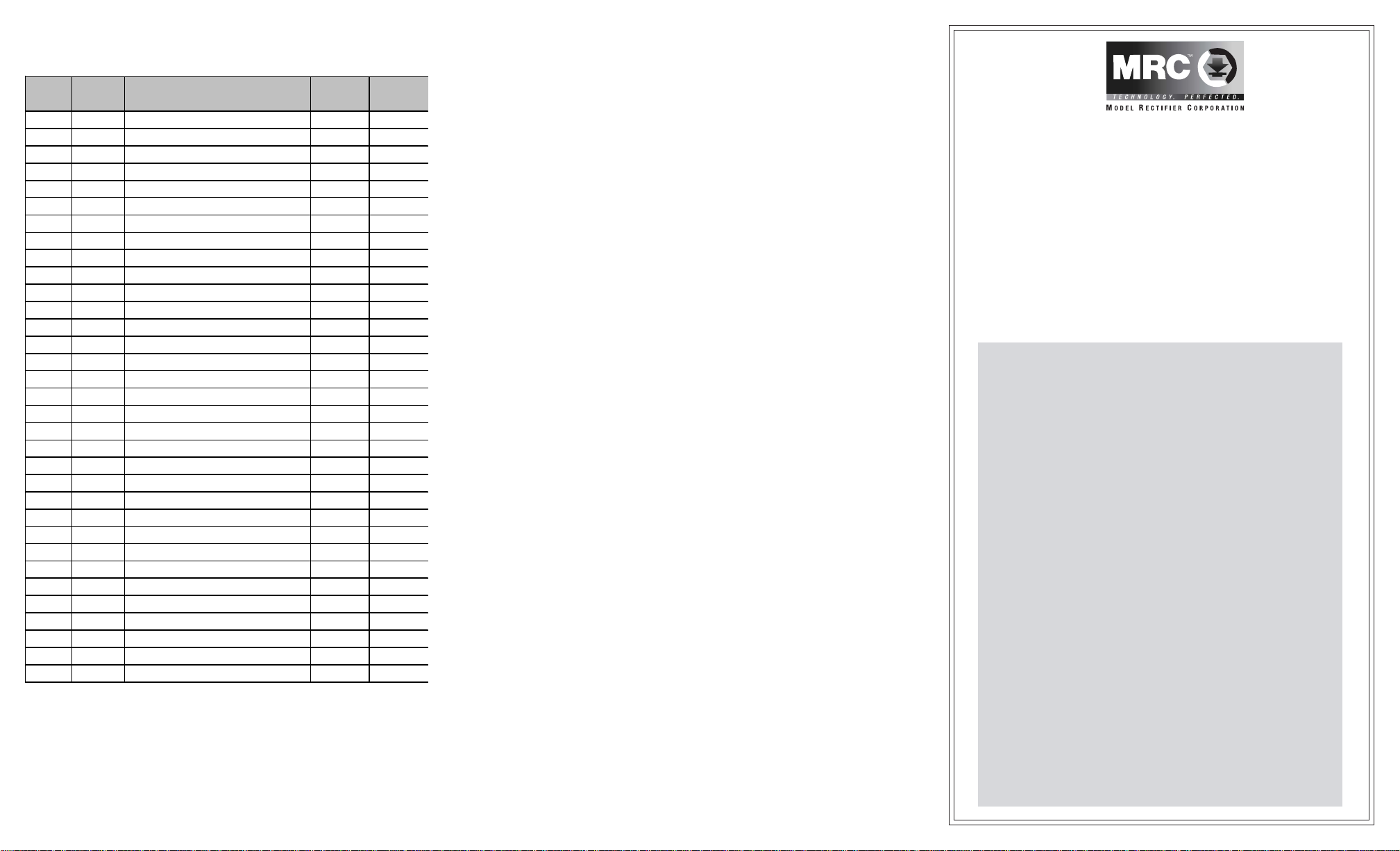
MAKE A TEST TRACK
Before you start with your decoder installation, we strongly recommend building a
test track that uses a 20-ohm resistor to limit current. Only test your installed
decoder on the test track. The test track will prevent any damage due to an
incorrectly wired decoder. Figure 3. Diagram of test track
TEST
All MRC decoders have been factory programmed with address #3, 28/128 speed
steps and maximum top voltage. After you have finished your decoder installation,
you are ready to test it. Never run the installed decoder on your layout without
first passing the test. You may damage the decoder if it is not wired correctly or if
you have not properly isolated the motor and the lights.
Put the loco on the test track. Select the Run Mode of your DCC system and select
or acquire address #3. Move up throttle and the loco should move forward. Push
the light button and the front light of your loco should turn on. Push the reverse
direction button. The loco should move backward and the rear light should turn on.
The loco cannot get normal speed because there is a 20-ohm protection resistor in
the test track. If you are able to turn on/off the front and rear lights and you are able
to move the loco forward and reverse, you did a great job. Congratulations! Do not
test the loco on the test track for an extended period of time. To do so will
cause the protection resistor to overheat.
If your installed decoder does not pass the test, find the problem, correct it and test
it again. As long as you test the decoder on the test track there is little chance of
damaging your decoder. This is why making a test track is so important.
OPERATION
This decoder can be operated with the diesel sounds on or off. Pressing F12
or double clicking your headlight button (F0) will turn the diesel sounds on or
off. When the diesel sounds are turned off, all accessory function sounds will
also be turned off.
Double clicking your bell button, (F1) will turn on or off the decoders accessory
lighting, (ditch, mars, or strobe lights). See programming chart to program this
feature.
There are three horn type sounds and two bell type sounds bulit into this
decoder for you to choose. See programming chart for selecting the type you
want.
DIESEL SOUNDS CHART
The long horn sound, (F2) will remain on when you activate it. To turn it off
press the F2 button again. This feature lets you pick the duration of the
horn blast for realistic horn signaling.
LIGHT EFFECT PROGRAMMING CHART FOR CV#112
Your MRC synchronized diesel sound decoder is equipped with normal
directional lighting, plus MRC light effects. By using the headlinght blue
common wire and a combination of the solder pads on the decoder board, (see
wiring diagram), you can choose from ditch lights or a mars light or a strobe
light. Also without any complicated wiring, just by simple programming, your
diesel locomotive can have “Rule 17” directional headlights.
INSTALLATION
It is quite a challenge to install a decoder into a locomotive. You should have some
basic electrical knowledge and soldering skills. If you do not have the above
requirements, please ask the dealer for help in installation.
Figure 1 shows the electrical circuit of most standard locomotives. The terminals of
the motor and light(s) are directly connected to the wheel pick-ups. Each type of
loco has its own method of electrical pick-up and distribution. The connection
between the wheels, motor and light(s) could be wires, clips, the body or chassis, a
PC board or any other type of conductor. Figure out your loco’s electrical system
and how to disconnect (isolate) the motor and light(s).
Figure 1. Connection of standard locomotive. Note: The ‘X’ marks indicate
where to disconnect (isolate).
The decoder will be inserted between the wheel pick-ups and the motor. The ‘X’
marks in Figure 1 show you where to disconnect (isolate).
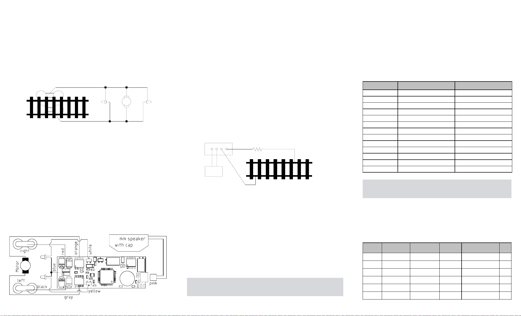
Figure 2. shows you how to wire the decoder. After disconnecting the motor
terminals from pick-ups, connect the red wire to the right side pick up and the black
wire to the left side pick up. Connect the orange wire to the motor terminal that
originally connected to the right pick up. Connect the gray wire to the motor’s other
terminal. Connect the front light to the blue wire and the white wire. Connect the
rear light to the blue wire and the yellow wire.
The blue wire is the common terminal for lights and accessory functions. You may
use the black wire or the red wire to replace the blue wire. This is very useful when
you find that it is hard to isolate one of the light terminals from the pick up. Wiring
the bulb this way will also make the light dimmer. If your loco has only a front light,
you should connect the white and the yellow wires together. If your locomotive has
a NMRA 8 pin receptacle, just remove the dummy plug and plug in the decoder.
Right side pickup
Front
light Motor Rear
light
Left side pickup
X X
X X X
X
Figure 2. 0001626 decoder wiring diagram
20
DCC base unit
Power supply
Test track
20 ohm resistor
Function Idle Moving
Double click F0 Sound on/off Sound on/off
F1 Bell on/off Bell on/off
F2 Long horn Long horn
F3 Shorthorn Shorthorn
F4 Conductor Coupling
F5 Brake release Brake
F6 Dynamic brake Dynamic brake
F7 Reverser Reverser
F8 air release Air release
F9 Coupler lift bar Air pump
F10 Sand Sand
F11 Exhaust Flange squeal
F12 Sound on/off Sound on/off
Light Head Light Rear Light Solder CV
Effect (white wire) (yellow wire) Pad #1 value
CV#112 Normal on/off Normal on/off Ditch light Ditch light 0
CV#112 Normal on/off Normal on/off Mars light Single strobe light 1
CV#112 Normal on/off Normal on/off Mars light Double strobe light 2
CV#112 Rule 17 Rule 17 Ditch light Ditch light 16
CV#112 Rule 17 Rule 17 Mars light Single strobe light 17
CV#112 Rule 17 Rule 17 Mars light Double strobe light 18
Solder Pad #2