manuals.online logo
Brands
  1. Home
  2. •
  3. Brands
  4. •
  5. MRP
  6. •
  7. Bicycle Accessories
  8. •
  9. MRP bartlett User manual

MRP bartlett User manual

MAINTENANCE DESCRIPTION FREQUENCY
(in hours)
REPLACE BATH OIL
NORMAL CONDITIONS:
50
MUDDY CONDITIONS: 30
REPLACE WIPER SEALS
NORMAL CONDITIONS:
100
MUDDY CONDITIONS: 75
CHANGE DAMPER OIL 200
CHECK FASTENERS 30
INSPECT STANCHIONS EVERY RIDE
CLEAN DIRT AND MUD FROM STANCHIONS EVERY RIDE
CHECK ADJUSTMENT CONTROLS EVERY RIDE
TORQUE VALUES
FASTENER TORQUE
COMPRESSION BOLT (DAMPER SIDE) 70-75 LB-IN 8 NM
COMPRESSION BOLT (AIR SPRING SIDE) 70-75 LB-IN 8 NM
CROWN PINCH BOLTS 70-75 LB-IN 8 NM
TOP CAPS 110 LB-IN 12 NM
REGISTER YOUR FORK ONLINE AT MRPBIKE.COM
A link to registration can be found under the “SUPPORT” heading.
While there check out our “TECH RESOURCES” section for more
information on the tuning, maintenance, and the technology found
in your MRP fork.
MRP IS A DIVISION OF:
MOUNTAIN RACING PRODUCTS
580 N WESTGATE DR.
GRAND JUNCTION, CO 81505
970.241.3518
GET THE LATEST INFO ON MRP PRODUCTS
Follow us on:
Facebook.com/MRPbike
Instagram.com/MRPbike
MAINTENANCE SCHEDULE
OWNER’S
MANUAL
IMPORTANT CONSUMER SAFETY INFORMATION
WARNING: RIDING A BIKE IS DANGEROUS. NOT PROPERLY
MAINTAINING OR INSPECTING YOUR BIKE AND ITS
COMPONENTS IS EVEN MORE DANGEROUS. IT IS ALSO
DANGEROUS TO NOT READ AND FOLLOW THESE
INSTRUCTIONS.
Thank you for choosing MRP. This owner’s manual is your
reference guide to using and fine-tuning your suspension fork
for optimum performance and comfort. It also provides important
information about the proper maintenance of your fork. Carefully
read this manual before installing your fork. If you need further
assistance, our experienced team is able to advise and assist you
to find the exact set up to meet your personal needs.
The fork is an important part of your mountain bike and
this owner’s manual explains how to install and use it properly.
We recommend that it be installed by a qualified bicycle
mechanic. Improperly installed forks might cause serious harm
to you and may severely damage your mountain bike. Never
take any chances with your safety. Before installing and using
your new fork, carefully read this owner’s manual to learn
the correct installation and adjustment procedures and avoid
the consequences of an incorrect installation or improper
adjustment.
When your fork requires an oil change or other internal
maintenance, MRP and experienced suspension service centers
are best qualified to provide the necessary service or repairs.
MAINTENANCE LOG
DATE PROCEDURE
WARRANTY:
MRP suspension products are the highest quality and as such are warranted to be
free from defects in materials and workmanship for a period of one year from the
date of purchase for the original purchaser. If date of purchase cannot be verified by
product registration or proof of purchase then the warranty is one year from the date
of manufacture. On receipt of the product by MRP, if it is found to be defective, MRP
will determine replacement or repair of the product at its sole discretion. MRP shall
not be liable for any indirect, special or consequential damages. Warranty does not
apply to any product that has been installed improperly or adjusted using methods
not outlined in this manual. Warranty also does not cover products that have been
misused or products that have missing/altered serial numbers. This warranty does not
cover breakage or damage that may result from crashes, falls, or abuse. Normal wear
and tear items such as; seals, wipers, bushings, stanchion coating, stanchions, piston
bands, foam rings, bottom out and top out bumpers, or damage caused by lack of
proper maintenance as outlined in this manual is not covered by this warranty.
What to do if you need warranty inspection or service:
1. Go to MRPbike.com and locate the warranty contact form in the support section of
the site. Alternatively, call or e-mail MRP (info@mrpbike.com) about the troubles you
are having and to set up a RA# (Return Authorization Number).
2. Carefully pack and ship your product, be sure to insure the package in case it is
lost or damaged in transit. Clearly write the RA number on the outside of the box.
(Only the return shipping to the customer is covered under warranty)
3. Wait for an e-mail confirming MRP has received your shipment.
FORK INSTALLATION
Dual-crown forks like the Bartlett are a little more dicult to install
compared to single-crown models. For this reason, if you are unsure
about any part of this procedure, consult a bike shop.
1. If applicable, remove your old fork from the bicycle. Measure the
length of your old fork’s steerer tube to ensure that the Bartlett’s steerer
tube is of sucient length for the installation.
2. Remove the crown race from your old fork (if applicable).
3. Press the crown race onto the Bartlett’s steerer tube.
4. Preassemble the headset by sliding the fork steerer tube through
the bearings. You may do this with or without the stanchions clamped
in the lower crown. Then install the headset’s upper race and other
parts, headset spacers (if desired underneath the upper crown), the
upper crown, additonal headset spacers (optional), and stem (if using a
traditional steerer tube-clamped stem) onto the steerer tube.
5. Mark the steerer tube at the top of the stem or spacers (if using a
direct-mount stem). The steerer tube will now need to be cut to the
correct length. Disassemble and cut 3mm (1/8”) below the mark. Consult
your dealer or mechanic if you don’t have the proper tools to cut the
steerer tube. We do not recommend using a pipe-cutter as it can deform
the steerer tube and make headset, spacer, and stem installation more
dicult.
6. The star nut must now be installed into the steerer tube. If you don’t
have the setting tool we recommend dealer installation of this part.
7. Clean and grease all headset bearings and races to prepare them for
assembly.
8. Now loosely assemble the full upper and lower clamp and steerer
assembly, and the fork bumpers, headset, spacers, and stem (if
applicable). Install the fork bumpers before installing the upper crown (if
applicable).
9. Install the headset top cap into the star nut. Tighten until there is
no play in the assembly. The fork or upper and lower clamp assembly
should rotate freely in the head tube.
10. If you haven’t already done so, install the rest of the fork onto the
crowns. Install the fork bumpers on the stanchions between the upper
and lower crowns (if applicable). Compared to fork travel, there must
be a minimum of an additional 5mm of stanchion showing between
the top of the wiper seals and the lower crown for 29” models and
12mm for 27.5” models (example: 29” with 190mm travel = 195mm of
visible stanchion). You may exceed those values if you’d like to adjust
the geometry of your bike.
11. With the fork height set, tighten the two lower clamp pinch bolts on
each side to 8 Nm. Then, the single pinch bolts on the upper crown (on
each side) to 8 Nm. And finally, the pinch bolt on the steerer tube to 8
Nm.
12. Install the wheel. Insert the axle through the disc brake side dropout,
through the hub and into the captive nut on the non-disc brake side
dropout. Using a 6mm hex tool, thread axle into the captive nut and
tighten to 12-15 Nm. DO NOT TIGHTEN THE BOLT-ON AXLE USING
THE 8mm HEX FITTING ON THE CAPTIVE NUT
13. After installation of the rest of the cockpit, install the brake caliper
onto the fork. Adjust your front brake according to the manufacturer’s
instructions.
14. Clamp the brake hose into the provided hose guide and install it on
the fork. Check to see that the brake is adjusted and working properly.
Make sure the brake line doesn’t interfere with any part of the bike when
the fork is compressed and released.
access to the cassette tool interface.
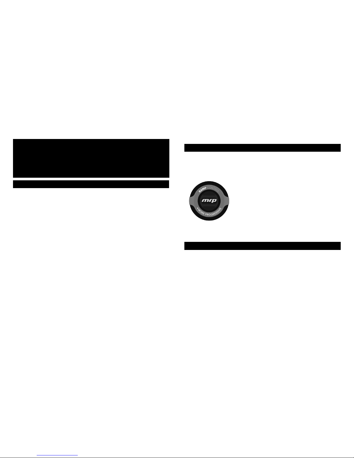
3. Unthread the Ramp Control cartridge assembly from the crown of the
fork using a cassette tool.
4. With the cartridge removed, install or remove Huck Pucks. Use up to
a 4mm hex key or something of similar diameter inserted into the side
of the pucks to tighten or loosen the pucks. Tighten any installed pucks
onto the bottom of the cartridge snugly so they do not come loose over
time.
5. Re-install the cartridge by threading it back into the fork crown and
tighten to 12 Nm.
6. Inflate the air spring as outlined in the previous section. Added Huck
Pucks will require slightly lower air pressure values to preserve the
previous sag level.
The compression adjustment knob is located on the top of the damper-
side fork leg. There are 8 clicks of adjustment. Your fork comes from
the factory in the first, least damped position.
COMPRESSION ADJUSTMENT
As you turn the dial clockwise, you are adding compression
damping or slowing the forks compression stroke. It is an adjustment
that is subtle, and often overlooked, but can make a big dierence
in how your fork performs. Aggressive riders tend to like more
compression damping because it provides a firmer, more supportive
feel. Comfort oriented, less aggressive riders tend to like less
damping in order to maximize small bump sensitivity. Do not confuse
compression damping with spring rate. They are very dierent
adjustments, and while adding compression damping may make the
fork feel “stier”, it is not changing the spring rate.
REBOUND ADJUSTMENT
Adjustments to rebound can be made by turning the red knob on the
bottom of the damper-side fork leg. The total usable range of rebound
adjustment on the Bartlett is approximately 20 clicks.
Rebound damping is what prevents your suspension fork from
feeling like a pogo stick. It controls the rebound stroke of the fork
after a compression stroke (bump) has occurred. Increasing (turn knob
clockwise) rebound damping slows the rebound stroke of the fork.
Decreasing (turn knob counter clockwise) rebound damping speeds up
the rebound stroke of the fork. Ideally, you want to arrive at a setting
that allows your wheel to track the terrain and not get bounced o line.
15. With all front-end parts of the bike installed, check again for proper
headset tightness by engaging the front brake and rocking the front of
the bike back and forth, looking for knocking in the headset. If needed,
loosen the upper crown bolts, tighten the headset top cap, and repeat
the relevant portions of step 11 to remove any play in the assembly.
AIR PRESSURE FILL PROCEDURE
1. Unthread and remove the negative air chamber cap found on the
bottom of the spring leg.
2. Attach a high-pressure, suspension specific pump to the valve and
using the pump’s bleed button, remove all pressure. Remove the pump.
3. Locate the positive air chamber cap at the top of the spring leg.
AIR SPRING SETUP
The Bartlett uses MRP’s FulFill™ air spring system with independent
positive and negative chambers. It is critical the you follow the steps
below in order for proper suspension function.
Because the Bartlett is a high-performance fork and its desired
feel is highly subjective, we recommend experimenting with dierent
air pressure settings in conjunction with Ramp Control settings and air-
volume modifications (using the included Huck Pucks).
In testing, we’ve found that the common usable range for air
pressure is between 90-200 PSI. A good starting point for most riders
seems to be a positive pressure (in PSI) equal to approximately
65-70% of body weight in pounds (lbs.). For example, a 175 lb. rider
should start with 118 PSI in the positive chamber. Most riders like slightly
more pressure in the negative chamber. You may inflate the negative
chamber to as much as 10% or 10 PSI (whichever is greater) more than
the positive chamber.
If you are unfamilar with lbs. (pounds) the conversion from kg.
(kilograms) is: kg. x 2.2 = lbs.
Here are some examples:
RIDER WEIGHT
150 lbs. / 68 kg.
175 lbs. / 79.5 kg.
200 lbs. /91 kg.
225 lbs. / 102 kg.
POSITIVE PRESSURE
101 PSI
118 PSI
135 PSI
152 PSI
NEGATIVE PRESSURE
105 - 111 PSI
122 - 130 PSI
140 - 149 PSI
158 - 167 PSI
IMPORTANT BRAKE INFORMATION:
THE BARTLETT FORK FEATURES A POST MOUNT FOR 180mm
ROTORS. SHOULD YOU WANT TO USE A LARGER ROTOR, MAKE
SURE TO USE THE APPROPRIATE DISC BRAKE ADAPTOR AS
RECOMMENDED BY YOUR BRAKE MANUFACTURER. FAILURE TO DO
SO COULD RESULT IN SERIOUS INJURY OR DEATH.
Unthread and remove the positive air chamber cap and attach a high-
pressure suspension specific pump to the valve.
4. Fill the positive air chamber to the desired pressure. Remove the
pump and re-install the positive air chamber cap.
5. Return to the negative air chamber; attach the pump, fill to the
desired pressure, remove the pump, and re-install the negative air
chamber cap.
RAMP CONTROL™ ADJUSTMENT
Ramp Control gives you the ability to
adjust, on-the-fly, the air spring’s ending-stroke
curve. Ramp Control is completely independent
of your damper or air spring pressure settings.
All MRP forks feature super-supple small-bump
compliance, but with Ramp Control you can set
your fork up to be super plush but still resist
bottoming. Cadillac-plushness not your thing? Dial back the Ramp
Control and up your pressure to enjoy a more linear fork that rides high
but uses every inch of travel eectively.
HUCK PUCK (AIR VOLUME) TUNING
The Bartlett comes stock with two Huck Pucks installed. You may
install as many as 5 total (3 additional) Huck Pucks. The installation of
Huck Pucks reduces the volume of the positive air spring and thereby
changes the overall spring curve. With additional Huck Pucks, the
biggest change occurs at the end of the stroke, where it becomes
more progressive (less susceptible to bottom-out). This change in
performance occurs at all compression speeds, where the Ramp
Control function mostly increases ending-stroke ramp on high-speed
compression events.
HUCK PUCK INSTALLATION OR REMOVAL
1. Release all air pressure from the negative air spring by depressing the
Schrader valve core on bottom of the air leg of the fork. Fully open the
Ramp Control adjustment and repeat the same for the positive spring
(at the top of the air leg of the fork). To ensure all air is released from
both chambers, cycle the fork 2-3 times and depress the positive valve
core again.
2. Use an 11mm socket to remove the lock nut on the positive spring’s
schrader valve and allow for removal of the Ramp Control knob and
The Ramp Control cartridge assembly is located at the top of the spring-side
fork leg, and adjusted via a 16-position knob there. Clockwise adjustment
of the knob will reduce the forks tendency to bottom-out on hard hits and
increase the ending-stroke spring curve.

Other MRP Bicycle Accessories manuals

MRP LOOP TR User manual

MRP

MRP LOOP TR User manual

MRP D-Mount 1x User manual

MRP

MRP D-Mount 1x User manual

MRP BAXTER User manual

MRP

MRP BAXTER User manual

MRP hazzard User manual

MRP

MRP hazzard User manual

MRP raven User manual

MRP

MRP raven User manual

MRP S4 User manual

MRP

MRP S4 User manual

MRP ribbon User manual

MRP

MRP ribbon User manual

MRP G3 Steel User manual

MRP

MRP G3 Steel User manual

MRP SXg User manual

MRP

MRP SXg User manual

Popular Bicycle Accessories manuals by other brands

Bike2Power SpinPower S1 user manual

Bike2Power

Bike2Power SpinPower S1 user manual

Kögel BSA30 installation manual

Kögel

Kögel BSA30 installation manual

OKBABY Body Guard manual

OKBABY

OKBABY Body Guard manual

King-Meter JUST TWO user guide

King-Meter

King-Meter JUST TWO user guide

NEXELO L177030NEX user manual

NEXELO

NEXELO L177030NEX user manual

Burley NOMAD RACK Owners manual & safety manual

Burley

Burley NOMAD RACK Owners manual & safety manual

SRAM Stealth-a-majig user manual

SRAM

SRAM Stealth-a-majig user manual

Cannondale IQ118 user guide

Cannondale

Cannondale IQ118 user guide

Cane Creek CANE CREEK THUDBUSTER instructions

Cane Creek

Cane Creek CANE CREEK THUDBUSTER instructions

ARC FEATHER user manual

ARC

ARC FEATHER user manual

Shimano FC-2200 Technical Service Instructions

Shimano

Shimano FC-2200 Technical Service Instructions

Bontrager Flare R manual

Bontrager

Bontrager Flare R manual

Shimano SL-BS79 user manual

Shimano

Shimano SL-BS79 user manual

Helite B'SAFE SDU SADDLE SENSOR user guide

Helite

Helite B'SAFE SDU SADDLE SENSOR user guide

Weehoo THRILL owner's manual

Weehoo

Weehoo THRILL owner's manual

MINOURA Extra Bike Cradle 3 instruction manual

MINOURA

MINOURA Extra Bike Cradle 3 instruction manual

Wahoo RPM SPEED quick start guide

Wahoo

Wahoo RPM SPEED quick start guide

Thule RideAlong 100106 instructions

Thule

Thule RideAlong 100106 instructions

manuals.online logo
manuals.online logoBrands
  • About & Mission
  • Contact us
  • Privacy Policy
  • Terms and Conditions

Copyright 2025 Manuals.Online. All Rights Reserved.