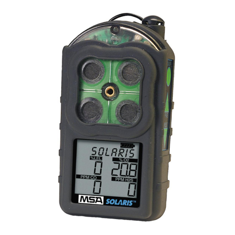
MSA Sirius User manual

1
SIRIUS®
[ MultiGas Detector ]
Instruction Manual
[Europe] Rev.03 / 11 2010 10092677 Y-HLS / GB
Manufactured by:
MSA INSTRUMENT DIVISION
P.O.Box 427, Pittsburgh, Pennsylvania 15230

2
Warranty and Liability Disclaimer
Observe handling instructions
Subassemblies sensitive to electrostatic discharge
This instrument consists of subassemblies which are electrostatically sensitive. Opening of
the instrument for maintenance or repair is to be carried out by authorized personnel only.
Avoid unprotected touching of the subassemblies causing electrostatic discharge.
Guarantee is voided if damages to subassemblies are caused by electrostatic discharge.
The liability of MSA is excluded if the product is not used appropriately and for the
intended purpose. Choice and use are in the sole responsibility of the acting
persons.
Warranties also as guarantees made by MSA with respect to the product are voided, if
it is not used, serviced or maintained in accordance with the instructions in this
manual.
The above corresponds to the terms and conditions of sale regarding the warranty
and liability of MSA. It does not alter them.
Liability Information
This product must be inspected and maintained in regular intervals by trained
specialists, records are to be kept. For service and repairs original MSA spare must
be used only. Inspections and maintenance must be made exclusively by authorised
service shops or MSA. The authorised service shops are responsible for
procurement of valid technical information for the product, components thereof and
maintenance instructions. Modifications to the product or components thereof are
not permissible and violate the approvals.
The liability of MSA extends exclusively to service and maintenance made by MSA.
MaintenanceAdvice
The SIRIUS Multigas Detector is a product supporting life and health!
This manual must be carefully read, understood and followed by all individuals who
have or will have the responsibility for selecting, using, servicing or maintaining this
product.
This manual contains instructions for the optimal use of the product as well as
important safety information.
Before use, the acting persons have to decide in accordance with this manual,
whether the product is suitable for the intended application.
Safety Advice

3
Table of Content
Table of Content
1. Instrument Safety and Certifications. ...........................................................................5
1.1 Safety Limitations and Precautions. ........................................................................6
1.2 Date of Instrument Manufacture. .............................................................................7
1.3 Marking, Certificates and Approvals according to the Directive 94/9/EC (ATEX). ..8
2. Quick Start. ....................................................................................................................10
2.1 Turning ON the SIRIUS Multigas Detector. ........................................................... 11
2.2 Moving through the SIRIUS Multigas Detector Pages. .........................................12
2.3 Turning Off the SIRIUS Multigas Detector. ............................................................12
3. Using the SIRIUS Multigas Detector. ..........................................................................13
3.1 Power Systems. .....................................................................................................13
3.2 Battery Pack Removal and Replacement. .............................................................13
3.3 Battery Charging (Lithium-Ion Battery Pack Only).................................................14
3.3.1 To Charge the Instrument. ...........................................................................15
3.4 Last Cal Date. ........................................................................................................15
3.5 Fresh Air Set Up Option (for automatic zero adjustment)......................................16
3.6 Battery Life Indicator. .............................................................................................16
3.6.1 Battery Warning. ..........................................................................................16
3.6.2 Battery Shutdown. .......................................................................................17
3.7 Sensor Missing Alarm. ...........................................................................................17
3.8 PIDAlarms. ............................................................................................................17
3.8.1 PID Bulb - Cal Now......................................................................................18
3.9 Verifying Pump Operation......................................................................................18
3.10 To Clear Pump Alarm. ............................................................................................ 19
3.11 Confidence Flash. ..................................................................................................19
3.11.1Safe LED. ....................................................................................................20
3.11.2Operating Beep. ..........................................................................................20
3.12 Calibration Check. .................................................................................................20
4. Measuring Gas Concentrations. .................................................................................21
4.1 Combustible Gases (% LEL). ................................................................................21
4.1.1 Oxygen Measurements (% O2). ...................................................................22
4.1.2 Toxic Gas and VOC Measurements. ...........................................................22
4.2 Viewing Optional Displays. ....................................................................................23
4.2.1 Peak Readings (PEAK). ..............................................................................23
4.2.2 Minimum Readings (MIN)............................................................................24
4.2.3 Short Term Exposure Limits (STEL). ...........................................................24
4.2.4 Time Weighted Average (TWA). ..................................................................25
4.2.5 Time and Date Display.................................................................................25
4.3 PID Setup............................................................................................................... 26
4.3.1 Displaying Current Response Factor...........................................................26
4.3.2 Changing Response Factor. ........................................................................26
4.3.3 Selecting a Custom Response Factor. ........................................................ 26
4.3.4 Changing PID Bulb Selection. .....................................................................27
4
Table of Content
5. Setting up the SIRIUS Multigas Detector.................................................................... 28
5.1 Changing Instrument Settings. ..............................................................................28
5.2 Accessing the Instrument Setup Mode. .................................................................28
5.3 Instrument Alarm Bypass Options. ........................................................................30
6. Calibration. ....................................................................................................................33
6.1 Calibrating the SIRIUS Multigas Detector..............................................................33
6.2 Calibration Flow Chart. ..........................................................................................34
6.3 Autocalibration Failure. ..........................................................................................36
7. Warranty, Maintenance, and Troubleshooting. ..........................................................37
7.1 MSA Portable Instrument Warranty........................................................................37
7.2 Cleaning and Periodic Checks. .............................................................................37
7.3 Removing and Cleaning the PID Bulb. ..................................................................38
7.3.1 Cleaning Steps. ...........................................................................................38
7.4 Replacing the Ion Chamber. ..................................................................................40
7.5 Replacing the Filters. .............................................................................................43
7.6 Storage...................................................................................................................45
7.7 Shipment. ...............................................................................................................45
7.8 Troubleshooting. ....................................................................................................45
7.9 Sensor Replacement. ............................................................................................47
7.10 Replacement of the Electronics Boards, the Display Assembly,
the Horn Assembly, and the Pump. .......................................................................48
8. Performance Specifications. .......................................................................................49
9. Replacement and Accessory Parts. ............................................................................60

5
1Instrument Safety and Certifications
1. Instrument Safety and Certifications
ATTENTION:
• Read and follow all instructions carefully.
• Check calibration before each day’s use and adjust if necessary.
• Check calibration more frequently if exposed to silicone, silicates, lead-containing
compounds, hydrogen sulfide, or high contaminant levels.
• Recheck calibration if unit is subjected to physical shock.
• Use only to detect gases/vapours for which a sensor is installed.
• Do not use to detect combustible dusts or mists.
• Make sure adequate oxygen is present.
• Do not block pump sample inlet and sensors.
• Use only Teflon sampling lines for reactive gases such as Cl2, PH3, NH3, HCN and
for semivolatile organic compounds such as gasoline and jet fuels.
• Do not place end of sampling line in liquids.
• Use only MSA-approved sampling lines.
• Do not use silicone tubing or sampling lines.
• Wait for accurate reading; response times vary, based on gas/vapor and length of
sampling line.
• Have a trained and qualified person interpret instrument readings.
• Account for sensor reproducibility.
• Properly identify the VOC gas being measured before using VOC response factors
or setting alarm values (exposures, STEL, TWA).
• Recognize that the VOC Auto-range displays readings in increments of 100 ppb.
• Ensure installed PID bulb corresponds to the PID bulb setting on the instrument
display.
• Do not recharge Lithium Ion battery or change Alkaline batteries in a combustible
atmosphere.
• Do not alter or modify instrument.
The SIRIUS Multigas Detector is for use by trained and qualified personnel. It is
designed to be used when performing a hazard assessment to:
• Assess potential worker exposure to combustible and toxic gases and vapours
• Determine the appropriate gas and vapor monitoring needed for a workplace.
The SIRIUS Multigas Detector can be equipped to detect:
• Combustible gases and certain combustible vapours
• Volatile organic compounds (VOCs)
• Oxygen-deficient or oxygen-rich atmospheres
• Specific toxic gases for which a sensor is installed.

6
Instrument Safety and Certifications1
1.1 Safety Limitations and Precautions
It is very important to have an understanding of PID basics when changing your
PID settings. Failure to properly identify the VOC gas being measured and/or
failure to select the correct Response Factor alarm values (exposure, STEL, TWA)
that match your desired Response Factor and/or the correct bulb, will result in
erroneous readings.
Carefully review the following safety limitations and precautions before placing this
instrument in service:
The SIRIUS Multigas Detector is designed to:
• Detect gases and vapours in air only
• Detect only specified toxic gases for which a sensor is installed.
Perform the following check before each day’s use to verify proper instrument operation:
• Calibration check (see 3.12 Calibration Check). Adjust calibration if the readings are
not within the specified limits.
Check calibration more frequently if the unit is subjected to physical shock or high levels
of contaminants. Also, check calibration more frequently if the tested atmosphere
contains the following materials, which may desensitize the combustible gas sensor and/
or VOC sensor (PID) and reduce its readings:
• Organic silicones
• Silicates
• Lead-containing compounds
• Hydrogen sulfide exposures over 200 ppm or exposures over 50 ppm for one
minute.
The minimum concentration of a combustible gas in air that can ignite is defined as the
Lower Explosive Limit (LEL). A combustible gas reading of “100” (in LEL mode) or “4.4”
(in CH4mode) indicates the atmosphere is at 100% LEL or 4.4% CH4(by volume),
respectively, and an explosion hazard exists. In such cases, the instrument LockAlarm
feature activates. Move away from contaminated area immediately.
Do not use the SIRIUS Multigas Detector to test for combustible or toxic gases in the
following atmospheres as this may result in erroneous readings:
• Oxygen-deficient or oxygen-rich atmospheres
• Reducing atmospheres
• Furnace stacks
• Inert environments
• Atmospheres containing combustible airborne mists/dusts
• Ambient pressures other than one atmosphere.
Do not use the SIRIUS Multigas Detector to test for combustible gases in atmospheres
containing vapours from liquids with a high flash point (above 38 °C, 100 °F) as this may
result in erroneously low readings.

7
1Instrument Safety and Certifications
Allow sufficient time for unit to display accurate reading. Response times vary based on
the type of sensor being utilized (see 8. Performance Specifications). Additionally,
when using a sampling line, allow a minimum of 3 seconds per meter of sampling line to
allow the sample to be drawn through the sensors.
Keep the probe tip above liquid surfaces; otherwise, liquid may enter the system and
block the sample flow, causing inaccurate readings and/or internal damage.
All instrument readings and information must be interpreted by someone trained and
qualified in interpreting instrument readings in relation to the specific environment,
industrial practice and exposure limitations.
Replace alkaline cells or recharge Li-Ion battery pack in non-hazardous areas only.
Use only battery chargers listed in this manual; other chargers may damage the battery
pack and the unit. Dispose of batteries in accordance with local health and safety
regulations.
Do not alter this instrument or make any repairs beyond those specified in this manual.
Only MSA-authorized personnel may repair this unit; otherwise, damage may result.
1.2 Date of Instrument Manufacture
The date of manufacture of your SIRIUS Multigas Detector is coded into the instrument
serial number.
• The last three digits represent the month (the letter) and the year (the two-digit
number).
• The letter corresponds to the month starting withA for January, B for February, etc.

8
Instrument Safety and Certifications1
1.3 Marking, Certificates and Approvals according to the
Directive 94/9/EC (ATEX)
Manufacturer: Mine SafetyAppliances Company
1000 Cranberry Woods Drive
Cranberry Township, PA16066 USA
Product: MSA SIRIUS
EC-Type Examination Certificate: BVS 05 ATEX E 025X
FTZU 05ATEX 0003X
Marking: II 2G EEx ia d IIC T3/T4
-20 °C ≤Ta ≤+50 °C
Battery: Alkaline T4: Duracell MN 15000
T3: Varta 4006, 4106, 4906, Energizer E91
Lithium Ion T4
Um = 6,54V
Type of protection: EN 50 014: 1997, EN 50 018: 2000, EN 50 020: 2002
The revised standards are compared to the standards used for the certification
and there are no changes in the "state of the art" applied to the Sirius.
Performance: EN 60 079-29-1: 2007, EN 50 104: 2004, EN 50 271: 2001
Gas: Methane, Pentane, Oxygen
QualityAssurance Notification: 0080
Year of Manufacture: see Label
Serial Nr.: see Label
EMC Conformance according to the Directive 2004/108 EC
EN 50270: 2007 Type 2, EN 61000-6-3: 2007

9
1Instrument Safety and Certifications
Declaration of Conformity
MANUFACTURED BY: Mine Safety Appliances Company
1000 Cranberry Woods Drive
Cranberry Township, PA 16066 USA
The manufacturer or the European Authorized Representative
MSAAUER GmbH, Thiemannstraße 1, D-12059 Berlin
declares that the product: SIRIUS
based on the EC-Type Examination Certificate:
BVS 05 ATEX E 025X
FTZU 05ATEX 0003X
complies with the ATEX directive 94/9/EC, Annex III. Quality Assurance Notification
complying with Annex IV of the ATEX Directive 94/9/EC has been issued by Ineris,
Notified Body number: 0080.
The product is in conformance with the directive 2004/108/EC, (EMC):
EN 50270: 2007 Type 2, EN 61000-6-3: 2007
The product is in conformance with the directive 2008/67/EC, (MarED):
EC-Type Examnination Certification: 213.037 Notified Body number: 0736
MSAAUER GmbH Berlin, March 2010
Dr. Axel Schubert
R & D Instruments

10
Quick Start2
2. Quick Start
It is your responsibility to know how to use the SIRIUS Multigas Detector. When used
properly the SIRIUS Multigas Detector will alert you to presence of VOC, combustible
gases and vapours, atmospheres that are rich or deficient in oxygen. It will also alert you
to presence of carbon monoxide and hydrogen sulphide, if it is equipped with sensors for
those gases. The conditions are displayed clearly and simultaneously on face of the
instrument, See Figure 1 for an explanation of the flags, numbers and button operation
on the SIRIUS Multigas Detector.
Figure 1:
Instruments Features
ON/
OFF/
ACCEPT
PAGE/
SCROLL UP
RESETALARM/
CALIBRATE/SCROLLDOWN
ALARM LIGHT
LAMPACCESS CAP
KEY PAD*
USER DISPLAY
D-RING
SAFE LEDPUMP INLET
ALARM LIGHT
BATTERY PACK
HORN
*KEY PAD

11
2Quick Start
2.1 Turning ON the SIRIUS Multigas Detector
Install the alkaline battery pack Lithium-Ion battery pack
or if already intalled press the ON-OFF/ACCEPT button.
The instrument then performs a Self-test and displays:
• All segments display
• Audible alarm sounds
• Alarm LEDs illuminate
• Display backlight illuminates
• Pump activates
• Software version displays
• Internal diagnostics
Alarm setpoints:
• Low
• High
• STEL (if activated)
• TWA (if activated)
•Calibration gas (expected calibration gas values)
•Time and date (if data logging option installed)
•Last CAL date (if data logging option installed)
•Instrument warm-up period
•Fresh Air Setup option
•Last Cal Date
Once the Self-test is complete, the imstrument enters the Measure mode and is ready for use.
Figure 2:
Understanding the Display
TEXT MESSAGE
HEARTBEAT
PPM VOC
READING
BATTERYINDICATOR
% OXYGEN
READING
PPM H2S
READING
PPM CO
READING
DIVIDERS
% LEL OR % CH4
READING

12
Quick Start2
2.2 Moving through the SIRIUS Multigas Detector Pages
Figure 3:
Flow diagram showing the operation of the instrument.
2.3 Turning Off the SIRIUS Multigas Detector
To turn OFF the SIRIUS Multigas Detector:
• Push and hold the ON-OFF/ACCEPT button for three seconds.
• Four audible beeps will be heard during the turn-off sequence.
RESPONSE
FACTORS
TIME/DATE
CLEAR
TWA
TWA
CLEAR
STEL
STEL
CLEAR
MIN
MIN
CLEAR
PEAK
PEAK
MEASURE
Ó
POWER
ON
RESET
RESET
RESET
RESET
PAGE
PAGE
PAGE
PAGE
PAGE
PAGE
PAGE
DATA LOGGING
INSTRUMENTS
ONLY
WAIT
30 SEC.
WAIT
30 SEC.
WAIT
30 SEC.
WAIT
30 SEC.
WAIT
30 SEC.
WAIT
30 SEC.
RESET
CHANGE
RF

13
3Using the SIRIUS Multigas Detector
3. Using the SIRIUS Multigas Detector
3.1 Power Systems
The SIRIUS Multigas Detector is supplied with a rechargeable Lithium-Ion battery pack
or a replaceable cell, alkaline batterypack.
3.2 Battery Pack Removal and Replacement (Figure 4)
To remove the battery pack from the SIRIUS Multigas Detector:
1. Unscrew the captive screw from the bottom of the battery door.
Figure 4: Battery Pack Removal
2. Pull the battery pack out of the instrument by gripping the sides
of the battery pack door and lifting it up and away from the unit.
See Table 1 for nominal run times by battery type. Note that there is a severe reduction
in run time for instruments operated at colder temperatures.
NOTE:
For both types of battery packs, always remove the batterypack from the instrument if
the instrument is not to be used for 30 days.
PULL BACK
THEN UP
UNSCREW
Table 1. Battery Type/Temperature/Approximate Run Time (Hours)
Battery Type 23 °C 0 °C -20 °C
Alkaline 6 4 1
Lithium-Ion 11 9 6

14
Using the SIRIUS Multigas Detector3
For Alkaline battery packs (Figure 5):
a. Pull the battery pack from the clip.
b. Unscrew the captive thumbscrew and lift the lid.
• The lid will remain on the thumbscrew.
c. Replace the batteries, using only batteries listed on the approval label T3:
Varta 4006/ Energizer E91, T4: Duracell MN1500 (see also chapter 1.3), and replace
the lid; tighten the thumbscrew.
d. Slide the battery pack into the clip and reinstall the door.
Figure 5: Changing Alkaline Batteries
3.3 Accumulator Charging (Lithium-Ion Battery Pack Only)
Charge the SIRIUS Multigas Detector Lithium-Ion battery pack by using the SIRIUS
Charger supplied with the instrument. The Lithium-Ion battery pack can be charged
while on or off the instrument.
Use of any charger, other than the SIRIUS Charger supplied with the instrument,
may damage or improperly charge the batteries.
• The SIRIUS Multigas Detector must be turned OFF, or the battery pack may be
removed from the instrument, prior to charging.
Charge Accumulator in non-hazardous areas only!
Change batteries in non-hazardous areas only!

15
3Using the SIRIUS Multigas Detector
3.3.1 To Charge the Instrument
• Snap the charger onto the instrument.
• Do not restrict or block the ventilation openings on either side of the charger.
• Charge status is indicated by the LED on the charger.
•Red: Charging in process
•Green: Charging complete
•Yellow: Failure Mode.
• If the red LED does not light and remain ON when the charger is attached, it is
possible:
• an incomplete electrical connection exists between the charger and the Lithium
Ion battery pack contact points or
• the temperature of the battery pack is outside of the previously indicated
range.
• During recharge, the red LED turning OFF and green LED not lighting is an
indication of an improper charging process. This is most likely caused by a battery
pack temperature being outside of the previously-indicated range.
• Restart the charging process with the battery pack in a different temperature
environment.
• Failure mode, indicated by the yellow LED, will occur if either:
• the battery pack has been deeply depleted beyond the point where it will accept
a charge
• an internal charger fault has been detected, which would result in an erroneous
charging condition.
• Charger may be left on the instrument when charge is complete.
NOTE:
If the instrument is not turned OFF, the charger connection will turn OFF the instrument
without warning.
• The charger is capable of charging a completely depleted pack in less than six
hours in normal, room-temperature environments.
Allow very cold battery packs to stabilize for one hour at room temperature before
attempting to charge.
• Minimum and maximum ambient temperature to charge the instrument:
10 °C (50 °F) to 35 °C (95 °F). Charging outside of this range may not be
successful.
• For best results, charge the instrument at room temperature (23 °C)
3.4 Last Cal Date
The SIRIUS Multigas Detector is equipped with a “last successful calibration date”
feature. The date shown is the last date at that all installed sensors were successfully
calibrated. “LAST CAL” is displayed with this date in the following format:
MM/DD/YY

16
Using the SIRIUS Multigas Detector3
When the SIRIUS Multigas Detector goes into Battery Warning:
• Battery Life indicator flashes
• “BATT WRN” flashes every 15 seconds
• Alarm sounds
• Lights flash every 15 seconds
• The SIRIUS Multigas Detector continues to operate until the instrument is turned
OFF or battery shutdown occurs.
• Turn ON the SIRIUS Multigas Detector.
• Once the instrument self check is complete, ZERO? flashes for 10 seconds.
• To perform a Fresh Air Setup, push the ON/OFF button while ZERO? is flashing.
• To immediately skip the FAS, push the RESET/TT
TT
Tbutton.
• If no buttons are pushed, the option of performing a Fresh Air Set Up stops flashing
after the 10 seconds have expired.
NOTE:
The Fresh Air Setup (FAS) has limits. If a hazardous level of gas is present, the
SIRIUS Multigas Detector ignores the FAS command and goes into alarm.
Persons responsible for the use of the SIRIUS Multigas Detector must determine
whether or not the Fresh Air Setup option should be used. The user’s abilities, training
and normal work practices must be considered when making this decision.
NOTE:
Duration of remaining instrument operation during Battery Warning depends on
ambient temperatures.
3.5 Fresh Air Set Up Option (for automatic zero adjustment)
3.6 Battery Life Indicator (see Figure 2)
• The battery condition icon continuously displays in the upper portion of the screen,
regardless of the selected page.
• As the battery charge dissipates, segments of the battery icon go blank until only the
outline of the battery icon remains.
3.6.1 Battery Warning
A Battery Warning indicates that a nominal 15 minutes of operation remain before
instrument batteries are completely depleted.

17
3Using the SIRIUS Multigas Detector
3.7 Sensor Missing Alarm
The SIRIUS Multigas Detector will enter the Sensor Missing alarm if the instrument de-
tects that an enabled sensor is not properly installed in the instrument. For O2, CO, and
H2S sensors, the Sensor Missing feature is checked when the instrument is turned ON
and when leaving the Setup mode. The combustible Sensor Missing feature is
continually monitored. If a sensor is detected as missing, the following occurs:
•SENSOR and MISSING flash on the display
• The flag above the sensor detected as missing flashes on the display
• Alarm sounds and lights flash
• Alarm can be silenced by pressing the RESET/TT
TT
Tbutton
• No other pages can be viewed
• After approximately one minute, the unit automatically turns OFF.
3.8 PID Alarms
The SIRIUS Multigas Detector will enter the Ion Error, PID Error or the PID Comm Error
if the instrument detects that the PID is not functioning properly. These errors are
continually monitored. The PID Failed Span Cal is monitored during calibration only.
If one of these errors is detected, the following occurs:
• The error name flashes on the display
• Alarm sounds and lights flash
• Alarm can be silenced by pressing the RESET/TT
TT
Tbutton
• No other pages can be viewed
• After approximately one minute, the unit automatically turns OFF.
3.6.2 Battery Shutdown
When the batteries can no longer operate the instrument, the instrument goes into
Battery Shutdown mode:
•LOW and BATTERY flash on the display
• Alarm sounds and lights flash
• Alarm can be silenced by pressing the RESET/TT
TT
Tbutton
• No other pages can be viewed
• After approximately one minute, the instrument automatically turns OFF.
WARNING:
When Battery Shutdown condition sounds, stop using the instrument; it can no longer
alert you of potential hazards since it does not have enough power to operate properly:
1. Leave the area immediately.
2. Turn OFF the instrument if it is ON.
3. Report to the person responsible for maintenance.
Recharging or replacing batteries must be done in a non-hazardous location only.

18
Using the SIRIUS Multigas Detector3
3.9 Verifying Pump Operation
1. Turn ON the SIRIUS Multigas Detector.
• The pump motor starts fast and then slows down as the instrument adjusts the
power to run the pump.
2. Once gas readings are displayed, plug the free end of the sampling line or probe.
• The pump motor shuts down and an alarm sounds
• PUMP ALARM will flash on the display
• The readings on the display may change.
Figure 6:
PUMP/ALARM
flashing on the display
3. When the pump inlet, sample line or probe is blocked, the pump alarm must
activate.
If the alarm does not activate:
a. Check the sample line and probe for leaks.
b. Once leak is fixed, recheck pump alarm by blocking the flow.
3.8.1 PID Bulb – Cal Now
This message may appear in the event that the instrument detects a potential problem
with the output of the PID sensor. When this occurs, the best course of action is to clean
the PID bulb (see 7.3 Removing and Cleaning the PID Bulb). This message is not a
replacement for daily bump checks.
WARNING!
If a Sensor Missing, PID Error, Ion Error, PID Failed Span Cal, or PID Comm condition
occurs, stop using the instrument; it can no longer alert you of potential hazards.
1. Leave the area immediately.
2. Turn OFF the instrument if it is ON.
3. Report to the person responsible for maintenance.

19
3Using the SIRIUS Multigas Detector
Figure 7: Heartbeat Indicator
3.11 Confidence Flash
In addition to the audible (brief horn sounding) and visual tests (all display segments
light and all alarm lights flash) that occur when the instrument turns on, this instrument is
equipped with a confidence heartbeat on the display that flashes periodically. This
informs the user that the display is functioning normally (see Figure 7).
4. Press the RESET/TT
TT
Tbutton to reset the alarm and restart the pump.
During operation, a pump alarm may occur when the:
• Flow system is blocked
• Pump is inoperative
• Sample lines are attached or removed.
NOTE:
When the instrument is in a gas alarm, the pump alarm may not display until gas alarm
is cleared.
3.10 To Clear Pump Alarm
1. Correct any flow blockage.
2. Press the RESET/TT
TT
Tbutton.
• The Pump will now restart.
NOTICE
Perform a blocked flow test before each day’s use. Do not use the pump, sample line,
or probe unless the pump alarm activates when the flow is blocked. Lack of an alarm is
an indication that a sample may not be drawn to the sensors, which could cause
inaccurate readings.
Never let the end of the sampling line touch or go under any liquid surface. If liquid is sucked
into the instrument, readings will be inaccurate and instrument could be damaged.

20
Using the SIRIUS Multigas Detector3
3.11.1 Safe LED
The SIRIUS Multigas Detector is equipped with an optional green “SAFE” LED which
flashes every 15 seconds under the following conditions
• The green SAFE LED is enabled
• Instrument is on the normal Measure Gases page
• Combustible reading is 0% LEL or 0% CH4
• Oxygen (O2) reading is 20.8%
• Carbon Monoxide (CO) reading is 0 ppm
• Hydrogen Sulfide (H2S) reading is 0 ppm
• VOC reading is 0 ppm
• No gas alarms are present (low or high)
• Instrument is not in Low Battery warning or alarm
• CO, H2S, VOC, STEL and TWA readings are 0 ppm.
3.11.2 Operating Beep
The SIRIUS Multigas Detector is equipped with an optional operating beep. This
operating beep activates every 30 seconds by momentarily beeping the horn and
flashing the alarm LEDs under the following conditions:
• Operating beep is enabled
• Instrument is on normal Measure Gases page
• Instrument is not in Battery warning
• Instrument is not in Gas alarm.
3.12 Calibration Check
The calibration check is simple and should only take about one minute.
Perform this calibration check before each day’s use for each installed sensor.
1. Turn ON the SIRIUS Multigas Detector in clean, fresh air.
2. Verify that readings indicate no gas is present.
3. Attach regulator (supplied with calibration kit) to the cylinder.
4. Connect tubing (supplied with calibration kit) to the regulator.
5. Attach other end of tubing to the instrument.
6. Open the valve on the regulator, if so equipped.
• The reading on the SIRIUS Multigas Detector display should be within the limits
stated on the calibration cylinder or limits determined by your company.
• If necessary, change cylinder to introduce other calibration gases.
• If readings are not within these limits, the SIRIUS Multigas Detector requires
recalibration. See 6.Calibration.
NOTE:
The presence of other calibration gases may cause the PID to indicate measuring error
by dashes for the displayed VOC reading.
Other manuals for Sirius
3
Table of contents
Other MSA Security Sensor manuals

MSA
MSA Evotech Operation instructions

MSA
MSA FL500 UV/IR User manual

MSA
MSA altair 4 Technical manual

MSA
MSA ALTAIR 5X PID User manual

MSA
MSA altair 4x User manual

MSA
MSA MMR Quick start guide

MSA
MSA Sirius User manual

MSA
MSA left/RIGHT User manual

MSA
MSA ALTAIR 5X User manual

MSA
MSA ALTAIR PRO H2S User manual

MSA
MSA Advantage 4000 Series User manual

MSA
MSA ALTAIR PRO Series User manual

MSA
MSA OptimAir 3000 User manual

MSA
MSA V-TEC PFL User manual

MSA
MSA ALTAIR5 User manual

MSA
MSA ALTAIR 5X User manual

MSA
MSA PointGuard Concrete Anchorage Connector... User manual

MSA
MSA FlameGard 5 UV/IR-E User manual

MSA
MSA G1 SCBA User manual

MSA
MSA ALTAIR 5X User manual