MSA Sirius User manual

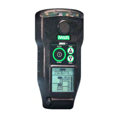
Sirius®
MultiGas Detector
Operating Manual
In North America, to contact your nearest stocking location, dial toll-free 1-800-MSA-2222
To contact MSA International, dial 1-412-967-3354 or 1-800-MSA-7777
© MINE SAFETY APPLIANCES COMPANY 2005 - All Rights Reserved
This manual is available on the internet at www.msanet.com
Manufactured by
MSA INSTRUMENT DIVISION
P.O. Box 427, Pittsburgh, Pennsylvania 15230
(L) Rev 2 10048887

i
THIS MANUAL MUST BE CAREFULLY READ BY ALL INDIVIDUALS WHO HAVE OR WILL
HAVE THE RESPONSIBILITY FOR USING OR SERVICING THE PRODUCT. Like any piece
of complex equipment, this instrument will perform as designed only if it is used and serv-
iced in accordance with the manufacturer’s instructions. OTHERWISE, IT COULD FAIL TO
PERFORM AS DESIGNED AND PERSONS WHO RELY ON THIS PRODUCT FOR THEIR
SAFETY COULD SUSTAIN SEVERE PERSONAL INJURY OR DEATH.
The warranties made by Mine Safety Appliances Company with respect to the product are
voided if the product is not used and serviced in accordance with the instructions in his
manual. Please protect yourself and others by following them. We encourage our cus-
tomers to write or call regarding this equipment prior to use or for any additional infor-
mation relative to use or repairs.
""WARNING

Table of Contents
Chapter 1,
Instrument Safety and Certifications . . . . . .1-1
"WARNING . . . . . . . . . . . . . . . . . . . . . . . . . . . . .1-1
Safety Limitations and Precautions . . . . . . . . . . . . . . . .1-2
"WARNING . . . . . . . . . . . . . . . . . . . . . . . . . . . . .1-2
Date of Instrument Manufacture . . . . . . . . . . . . . . . . . . .1-4
Certifications . . . . . . . . . . . . . . . . . . . . . . . . . . . . . . . . . .1-4
Electronic Interference . . . . . . . . . . . . . . . . . . . . . . . . . .1-4
Chapter 2, PID Theory and Definitions . . . . .2-1
PID Theory . . . . . . . . . . . . . . . . . . . . . . . . . . . . . . . . . . .2-1
Figure 2-1. Typical Photoionization Sensor Design .2-1
Zero Gas . . . . . . . . . . . . . . . . . . . . . . . . . . . . . . . . . . .2-2
Span Gas . . . . . . . . . . . . . . . . . . . . . . . . . . . . . . . . . . .2-2
Response Factors . . . . . . . . . . . . . . . . . . . . . . . . . . . .2-2
"WARNING . . . . . . . . . . . . . . . . . . . . . . . . . . . . .2-2
Calculating a Response Factor . . . . . . . . . . . . . . . . . .2-3
"WARNING . . . . . . . . . . . . . . . . . . . . . . . . . . . . .2-4
Chapter 3,
Using the Sirius Multigas Detector . . . . . . . .3-1
Figure 3-1. Instrument Features . . . . . . . . . . . . . . .3-1
Figure 3-2. Understanding the Display . . . . . . . . . .3-2
Turning ON the Sirius Multigas Detector . . . . . . . . . . . .3-3
Last Cal Date . . . . . . . . . . . . . . . . . . . . . . . . . . . . . . . . .3-3
Fresh Air Set Up Option . . . . . . . . . . . . . . . . . . . . . . . . .3-4
"WARNING . . . . . . . . . . . . . . . . . . . . . . . . . . . . .3-4
Battery Life Indicator (FIGURE 3-3) . . . . . . . . . . . . . .3-5
Battery Warning . . . . . . . . . . . . . . . . . . . . . . . . . . . . .3-5
Battery Shutdown . . . . . . . . . . . . . . . . . . . . . . . . . . . .3-5
Figure 3-3. Battery Indicator . . . . . . . . . . . . . . . . . .3-5
Sensor Missing Alarm . . . . . . . . . . . . . . . . . . . . . . . . .3-6
"CAUTION . . . . . . . . . . . . . . . . . . . . . . . . . . . . . .3-6
"WARNING . . . . . . . . . . . . . . . . . . . . . . . . . . . . .3-6
ii

"WARNING . . . . . . . . . . . . . . . . . . . . . . . . . . . . .3-6
PID Alarms . . . . . . . . . . . . . . . . . . . . . . . . . . . . . . . . . .3-7
PID Bulb -Cal Now . . . . . . . . . . . . . . . . . . . . . . . . . . . .3-7
"WARNING . . . . . . . . . . . . . . . . . . . . . . . . . . . . .3-7
Verifying Pump Operation . . . . . . . . . . . . . . . . . . . . . . .3-8
Figure 3-4a. Pump Alarm on the Display . . . . . . . . .3-8
Figure 3-4b. Pump Alarm on the Display . . . . . . . . .3-8
To Clear an Alarm . . . . . . . . . . . . . . . . . . . . . . . . . . . .3-9
Calibration Check . . . . . . . . . . . . . . . . . . . . . . . . . . . . . .3-9
"WARNING . . . . . . . . . . . . . . . . . . . . . . . . . . . . .3-9
Measuring Gas Concentrations . . . . . . . . . . . . . . . . . .3-10
Combustible gases (% LEL) (FIGURE 3-5) . . . . . . . .3-10
Figure 3-5a. Instrument in LEL Alarm . . . . . . . . . .3-10
"WARNING . . . . . . . . . . . . . . . . . . . . . . . . . . . .3-11
Figure 3-5b. Instrument in LEL Alarm . . . . . . . . . .3-11
Oxygen Measurements (% O2) (FIGURE 3-6) . . . . .3-12
Figure 3-6a. Instrument in Oxygen Alarm . . . . . . .3-12
Figure 3-6b. Instrument in Oxygen Alarm . . . . . . .3-12
Toxic Gas and VOC Measurements (FIGURE 3-7) . . .3-13
"WARNING . . . . . . . . . . . . . . . . . . . . . . . . . . . .3-13
Figure 3-7a. Instrument in VOC Gas Alarm . . . . . .3-13
Confidence Flash . . . . . . . . . . . . . . . . . . . . . . . . . . .3-14
"WARNING . . . . . . . . . . . . . . . . . . . . . . . . . . . .3-14
Figure 3-7b. Instrument in VOC Gas Alarm . . . . . .3-14
Safe LED . . . . . . . . . . . . . . . . . . . . . . . . . . . . . . . . . .3-15
Operating Beep . . . . . . . . . . . . . . . . . . . . . . . . . . . . .3-15
Figure 3-8. Heartbeat . . . . . . . . . . . . . . . . . . . . . . .3-15
Viewing Optional Displays (FIGURE 3-9) . . . . . . . . . .3-16
Figure 3-9. Flow Diagram . . . . . . . . . . . . . . . . . . .3-16
Peak Readings (PEAK) (FIGURE 3-10) . . . . . . . . . .3-17
Minimum Readings (MIN) (FIGURE 3-11) . . . . . . . . .3-17
Figure 3-10. PEAK Readings on the Display . . . .3-17
Figure 3-11. MIN Reading on the Display . . . . . . .3-17
Short Term Exposure Limits (STEL) (FIGURE 3-12) .3-18
To Reset the STEL: . . . . . . . . . . . . . . . . . . . . . . . . . .3-18
Figure 3-12. Exposure Page with STEL Alarm . . .3-18
Time Weighted Average (TWA) (FIGURE 3-13) . . . .3-19
"WARNING . . . . . . . . . . . . . . . . . . . . . . . . . . . .3-19
Figure 3-13. Exposure Page with TWA Alarm . . . .3-19
iii

To Reset the TWA: . . . . . . . . . . . . . . . . . . . . . . . . . .3-20.
"WARNING . . . . . . . . . . . . . . . . . . . . . . . . . . . .3-20
Time and Date Display (FIGURE 3-14) . . . . . . . . . . .3-21
PID Setup . . . . . . . . . . . . . . . . . . . . . . . . . . . . . . . . .3-21
Displaying Current Response Factor . . . . . . . . . . . . .3-21
Figure 3-14 Time Display . . . . . . . . . . . . . . . . . . . .3-21
"WARNING . . . . . . . . . . . . . . . . . . . . . . . . . . . .3-21
Changing Response Factor . . . . . . . . . . . . . . . . . . . .3-22
Selecting a Custom Response Factor . . . . . . . . . . . .3-22
Figure 3-15. PID RF Page . . . . . . . . . . . . . . . . . . .3-22
Changing PID Bulb Selection . . . . . . . . . . . . . . . . . .3-23
Figure 3-14. Changing PID Bulb Selection . . . . . .3-23
"WARNING . . . . . . . . . . . . . . . . . . . . . . . . . . . .3-24
Turning OFF the Sirius Multigas Detector . . . . . . . . .3-25
Chapter 4,
Setting up the Sirius Multigas Detector . . . .4-1
"WARNING . . . . . . . . . . . . . . . . . . . . . . . . . . . . .4-1
Power Systems . . . . . . . . . . . . . . . . . . . . . . . . . . . . . . .4-1
Table 4-1. Battery Type/Temperature/
Approximate Run Time (Hours) . . . . . . . . . . .4-1
Table 4-2. Battery Type/Temperature Class . . . . . .4-1
Battery Pack Removal and Replacement . . . . . . . . . .4-1
Figure 4-1. Battery Pack Removal . . . . . . . . . . . . . .4-2
Figure 4-2. Changing Alkaline Batteries . . . . . . . . .4-2
Battery Charging (Lithium-Ion Battery Pack Only) . . .4-3
To Charge the Instrument . . . . . . . . . . . . . . . . . . . . . .4-3
"CAUTION . . . . . . . . . . . . . . . . . . . . . . . . . . . . . .4-3
Changing Instrument Settings . . . . . . . . . . . . . . . . . . . .4-4
Accessing the Instrument Setup Mode . . . . . . . . . . . . .4-4
Figure 4-3.. Entering the Set-up Mode . . . . . . . . . .4-5
Instrument Alarm Bypass Options . . . . . . . . . . . . . . . .4-6
"WARNING . . . . . . . . . . . . . . . . . . . . . . . . . . . . .4-8
"WARNING . . . . . . . . . . . . . . . . . . . . . . . . . . . . .4-9
iv

Chapter 5, Calibration . . . . . . . . . . . . . . . . . .5-1
"WARNING . . . . . . . . . . . . . . . . . . . . . . . . . . . . .5-1
Calibrating the Sirius Multigas Detector . . . . . . . . . . . . .5-1
Table 5-1. Autocalibration and
Required Calibration Cylinders . . . . . . . . . . .5-1
To Calibrate the Sirius Multigas Detector . . . . . . . . . .5-2
Figure 5-1. Calibration Flow Chart . . . . . . . . . . . . . .5-2
Figure 5-2a. Zero Flag . . . . . . . . . . . . . . . . . . . . . . .5-3
Figure 5-2b. Zero Flag . . . . . . . . . . . . . . . . . . . . . . .5-3
Figure 5-3a. CAL Flag . . . . . . . . . . . . . . . . . . . . . . .5-4
Figure 5-3b. CAL Flag . . . . . . . . . . . . . . . . . . . . . . .5-4
Autocalibration Failure . . . . . . . . . . . . . . . . . . . . . . . . .5-5
Chapter 6, Warranty, Maintenance, and
Troubleshooting . . . . . . . . . . . . . . . . . . . . . . .6-1
MSA Portable Instrument Warranty . . . . . . . . . . . . . . . .6-1
Cleaning and Periodic Checks . . . . . . . . . . . . . . . . . . . .6-2
Removing and Cleaning the PID Bulb . . . . . . . . . . . . .6-2
"WARNING . . . . . . . . . . . . . . . . . . . . . . . . . . . . . .6-2
Cleaning Steps . . . . . . . . . . . . . . . . . . . . . . . . . . . . . . .6-3
"CAUTION . . . . . . . . . . . . . . . . . . . . . . . . . . . . . .6-3
Figure 6-1. Cleaning the PID Bulb . . . . . . . . . . . . . .6-4
"WARNING . . . . . . . . . . . . . . . . . . . . . . . . . . . . .6-4
Replacing the Ion Chamber . . . . . . . . . . . . . . . . . . . . .6-5
"CAUTION . . . . . . . . . . . . . . . . . . . . . . . . . . . . . .6-5
"WARNING . . . . . . . . . . . . . . . . . . . . . . . . . . . . .6-5
Figure 6-2a. Ion Chamber Removal . . . . . . . . . . . .6-6
"CAUTION . . . . . . . . . . . . . . . . . . . . . . . . . . . . . .6-6
Figure 6-2b. Ion Chamber Removal . . . . . . . . . . . .6-7
Figure 6-3a. Ion Chamber Housing Cleaning . . . . .6-8
Figure 6-3b. Ion Chamber Cleaning . . . . . . . . . . . .6-8
Replacing the Filters . . . . . . . . . . . . . . . . . . . . . . . . . .6-9
Dust AND WATER Filter . . . . . . . . . . . . . . . . . . . . . . . .6-9
Figure 6-4. Ion Chamber Installation . . . . . . . . . . . .6-9
"CAUTION . . . . . . . . . . . . . . . . . . . . . . . . . . . . . .6-9
"WARNING . . . . . . . . . . . . . . . . . . . . . . . . . . . . .6-9
v

Figure 6-5. Filter Installation . . . . . . . . . . . . . . . . .6-10
Figure 6-6. Case Oval-shaped O-ring . . . . . . . . . .6-10
Probe Filter . . . . . . . . . . . . . . . . . . . . . . . . . . . . . . . . . .6-11
"WARNING . . . . . . . . . . . . . . . . . . . . . . . . . . . .6-11
Figure 6-7. Replacing the Probe Filter . . . . . . . . . .6-11
Storage . . . . . . . . . . . . . . . . . . . . . . . . . . . . . . . . . . . . .6-12
Shipment . . . . . . . . . . . . . . . . . . . . . . . . . . . . . . . . . . .6-12
Troubleshooting . . . . . . . . . . . . . . . . . . . . . . . . . . . . . .6-12
"WARNING . . . . . . . . . . . . . . . . . . . . . . . . . . . . .6-12
Table 6-1. Troubleshooting Guidelines . . . . . . . . .6-13
Sensor Replacement . . . . . . . . . . . . . . . . . . . . . . . . .6-13
Figure 6-8. Sensor Locations . . . . . . . . . . . . . . . . .6-14
Replacement of the Electronics Boards, the Display
Assembly, the Horn Assembly, and the Pump . . . . .6-15
"WARNING . . . . . . . . . . . . . . . . . . . . . . . . . . . .6-15
Chapter 7, Performance Specifications . . . .7-1
Table 7-1. Certifications (see instrument label to
determine applicable approval) . . . . . . . . . . .7-1
Table 7-2. Instrument Specifications . . . . . . . . . . .7-1
Table 7-3. COMBUSTIBLE GAS -
Typical Performance Specifications . . . . . . . .7-2
Table 7-4. COMBUSTIBLE GAS -
Cross Reference Factors for
Sirius General-Purpose Calibration
Using Calibration Cylinder (P/N 10045035)
Set to 58% LEL Pentane Simulant . . . . . . . . .7-2
Table 7-5. OXYGEN - Typical Performance
Specifications . . . . . . . . . . . . . . . . . . . . . . . . .7-4
Environment and Oxygen Sensor Readings . . . . . . .7-4
Pressure Changes . . . . . . . . . . . . . . . . . . . . . . . . . . . .7-4
Humidity Changes . . . . . . . . . . . . . . . . . . . . . . . . . . . .7-4
Temperature Changes . . . . . . . . . . . . . . . . . . . . . . . . .7-5
Table 7-6. CARBON MONOXIDE
(appropriate models only) -
Typical Performance Specifications . . . . . . . .7-5
Table 7-7. CARBON MONOXIDE -
Cross Reference Factors for
Sirius Calibration
Using Calibration Cylinder (P/N 10045035) . .7-6
vi
Table 7-8. HYDROGEN SULFIDE
(appropriate models only) -
Typical Performance Specifications . . . . . . . .7-7
Table 7-9. HYDROGEN SULFIDE -
Cross Reference Factors for
Sirius Calibration Using Calibration Cylinder
(P/N10045035) . . . . . . . . . . . . . . . . . . . . . . . .7-7
Table 7-10. PID (appropriate models only) -
Typical Performance Specifications . . . . . . . .7-8
Table 7-11. PID Response Factor Table . . . . . . . .7-9
"WARNING . . . . . . . . . . . . . . . . . . . . . . . . . . . . .7-13
"WARNING . . . . . . . . . . . . . . . . . . . . . . . . . . . .7-13
Table 7-12. Known Interference Data
for listed VOCs . . . . . . . . . . . . . . . . . . . . . . .7-14
"WARNING . . . . . . . . . . . . . . . . . . . . . . . . . . . .7-14
"WARNING . . . . . . . . . . . . . . . . . . . . . . . . . . . .7-15
Chapter 8,
Replacement and Accessory Parts . . . . . . . .8-1
Table 8-1. Accessory Parts List . . . . . . . . . . . . . . .8-1
Table 8-2. Replacement Parts List . . . . . . . . . . . .8-3
vii

1-1
Chapter 1,
Instrument Safety and Certifications
The Sirius Multigas Detector is for use by trained and qualified
personnel. It is designed to be used when performing a hazard
assessment to:
• Assess potential worker exposure to combustible and toxic gases
and vapors
• Determine the appropriate gas and vapor monitoring needed for a
workplace.
The Sirius Multigas Detector can be equipped to detect:
• Combustible gases and certain combustible vapors
• Volatile organic compounds (VOCs)
• Oxygen-deficient or oxygen-rich atmospheres
• Specific toxic gases for which a sensor is installed.
• Read and follow all instructions carefully.
• Check calibration before each day's use and adjust
if necessary.
• Check calibration more frequently if exposed to
silicone, silicates, lead-containing compounds,
hydrogen sulfide, or high contaminant levels.
• Recheck calibration if unit is subjected to physical shock.
• Use only to detect gases/vapors for which a sensor
is installed.
• Do not use to detect combustible dusts or mists.
• Make sure adequate oxygen is present.
• Do not block pump sample inlet.
• Use only Teflon sampling lines for reactive gases such as
Cl2, PH3, NH3, HCN, and for semivolatile organic compounds
such as gasoline and jet fuels.
• Use only MSA-approved sampling lines.
• Do not use silicone tubing or sampling lines.
• Wait sufficient time for the reading; response times vary,
based on gas/vapor and length of sampling line.
""WARNING

1-2
• Have a trained and qualified person interpret
instrument readings.
• Account for sensor reproducibility.
• Properly identify the VOC gas being measured before using
VOC response factors or setting alarm values (exposures,
STEL, TWA).
• Recognize that the VOC Auto-range displays readings in
increments of 100 ppb.
• Ensure installed PID bulb corresponds to the PID bulb
setting on the instrument display.
• Do not remove battery pack from instrument while in a
hazardous atmosphere.
• Do not take spare battery packs into a hazardous
atmosphere. Battery packs must be properly attached to the
instrument at all times.
• When they are to be discarded, properly dispose of alkaline
cells and the Li-Ion battery pack.
• Do not recharge Lithium Ion battery or change Alkaline
batteries in a hazardous location.
• Do not alter or modify instrument.
INCORRECT USE CAN CAUSE SERIOUS PERSONAL
INJURY OR DEATH.
Safety Limitations and Precautions
It is very important to have an understanding of PID basics
when changing your PID settings. Failure to properly identi-
fy the VOC gas being measured and/or failure to select the
correct Response Factor alarm values (exposure, STEL,
TWA) that match your desired Response Factor and/or the
correct bulb, will result in erroneous readings that could
lead to serious injury or death.
Carefully review the following safety limitations and precautions before
placing this instrument in service:
• The Sirius Multigas Detector is designed to:
• Detect gases and vapors in air only
• Detect only specified toxic gases for which a sensor is
installed.
• Perform the following check before each day's use to verify proper
instrument operation:
• Calibration check (see Calibration Check section). Adjust
calibration if the readings are not within the specified limits.
""WARNING

• Check calibration more frequently if the unit is subjected to
physical shock or high levels of contaminants. Also, check
calibration more frequently if the tested atmosphere contains the
following materials, which may desensitize the combustible gas
sensor and/or VOC sensor (PID) and reduce its readings:
• Organic silicones
• Silicates
• Lead-containing compounds
• Hydrogen sulfide exposures over 200 ppm or exposures
over 50 ppm for one minute.
• The minimum concentration of a combustible gas in air that can
ignite is defined as the Lower Explosive Limit (LEL). A combustible
gas reading of "100" (in LEL mode) or “5.00” (in CH4mode)
indicates the atmosphere is at 100% LEL or 5.00% CH4 (by
volume), respectively, and an explosion hazard exists. In such
cases, the instrument LockAlarm feature activates. Move away
from contaminated area immediately.
• Do not use the Sirius Multigas Detector to test for combustible or
toxic gases in the following atmospheres as this may result in
erroneous readings:
• Oxygen-deficient or oxygen-rich (greater than 21% by
volume) atmospheres
• Reducing atmospheres
• Furnace stacks
• Inert environments
• Atmospheres containing combustible airborne mists/dusts
• Ambient pressures other than one atmosphere.
• Do not use the Sirius Multigas Detector to test for combustible
gases in atmospheres containing vapors from liquids with a high
flash point (above 38°C, 100°F) as this may result in erroneously
low readings.
• Allow sufficient time for unit to display accurate reading. Response
times vary based on the type of sensor being utilized (see Chapter
7, Performance Specifications ).
• All instrument readings and information must be interpreted by
someone trained and qualified in interpreting instrument readings
in relation to the specific environment, industrial practice and
exposure limitations.
• Replace alkaline batteries in non-hazardous areas only. Use only
batteries listed on the approval label.
1-3

• Recharge the battery in non-hazardous area only. Use only battery
chargers listed in this manual; other chargers may damage the
battery pack and the unit. Dispose of batteries in accordance with
local health and safety regulations.
• Do not alter this instrument or make any repairs beyond those
specified in this manual. Only MSA-authorized personnel may
repair this unit; otherwise, damage may result.
Date of Instrument Manufacture
The date of manufacture of your Sirius Multigas Detector is coded into
the instrument serial number.
• The last three digits represent the month (the letter) and the year
(the two-digit number).
• The letter corresponds to the month starting with A for January, B
for February, etc.
Certifications
Tests completed by MSA verify that the Sirius Multigas Detector meets
applicable industry and government standards as of the date of
manufacture. See TABLE 7-1.
Electronic Interference
• This instrument generates, uses, and can radiate radio frequency
energy. Operation of this instrument may cause interference, in
which case, the user may be required to correct.
• This device is test equipment and is not subject to FCC technical
regulations. However, it has been tested and found to comply with
the limits for a Class A digital device specified in Part 15 of the
FCC regulations.
• This digital apparatus does not exceed the Class A limits for radio
noise emissions from digital apparatus set out in the Radio
Interference Regulations of the CRTC.
• There is no guarantee that interference will not occur. If this
instrument is determined to cause interference to radio or
television reception, try the following corrective measures:
• Reorient or relocate the receiving antenna
• Increase separation between the instrument and the
radio/TV receiver
• Consult an experienced radio/TV technician for help.
1-4

Chapter 2,
PID Theory and Definitions
To support the safe and effective operation of the Sirius Multigas
Detector, MSA believes operators should have a working knowledge of
how the instrument functions, not just how to make it work. The
information presented in this section supplements the hands-on
operational instruction provided in the rest of the manual for the PID.
PID Theory
A photoionization detector (PID) uses an ultraviolet lamp to ionize the
compound of interest. A current is produced and the concentration of
the compound is displayed in parts per million on the instrument meter.
Figure 2-1. Typical Photoionization Sensor Design
2-1

Zero Gas
Zero gas is a reference gas used during calibration to zero the
instrument. When a zero gas with no hydrocarbon content is introduced
to the monitor, the detector will still respond with a small signal. This
signal is a result of secondary background processes. During
calibration, zero gas is applied to quantify the background ionization
current.
For applications in which you are only interested in concentration
changes relative to a reference ambient environment, fresh air can be
used as the zero gas. When background hydrocarbon vapors are
present, MSA recommends using zero gas air or a carbon filter on the
inlet to zero the unit (See Chapter 8, TABLE 8-1, Accessory Parts
List).
Span Gas
Span gas is a reference gas used during calibration to determine the slope
(response per unit concentration) of the calibrated response curve.
Span Gas Recommendation: MSA strongly recommends use of an MSA
100 ppm isobutylene cylinder for calibration. See Chapter 5,
Calibration for calibration instructions.
Response Factors
When a compound is ionized by a photoionization detector, it yields a
current. This response is a characteristic property of the specific
compound which is influenced by its molecular structure. The slope of
the response curve (defined in picoamperes per ppm) is different for
different chemicals. To properly report the concentration for a given
sample gas, the Sirius Multigas Detector uses response factors. See
Chapter 3, Using the Sirius Multigas Detector - PID Setup, for
instructions on using the pre-programmed list of response factors.
It is very important to have an understanding of PID basics
when changing your PID settings. Failure to properly identi-
fy the VOC gas being measured and/or failure to select the
correct Response Factor alarm values (exposure, STEL,
TWA) that match your desired Response Factor and/or the
correct bulb, will result in erroneous readings that could
lead to serious injury or death.
""WARNING
2-2

The response factor is defined as the ratio of the detector response for
isobutylene to the detector response for the sample gas. Response
factors for a wide range of substances have been determined
experimentally. These response factors are programmed into the
instrument. Note that the calibrated response curve, and all
programmed response factors are relative to isobutylene. (Isobutylene
has a response factor of one.)
The response factor is a multiplier that compensates for the difference
between the response of the sample gas and the response of
isobutylene. Whenever the monitor detects a signal, it uses the
response factor for that chemical to convert the signal to the correct,
displayed concentration of the sample gas (if its identity is known).
During calibration, this calculation is performed to define the calibrated
response curve. When sampling, the isobutylene equivalent response is
then multiplied by the response factor for the specific sample gas to
calculate the concentration.
If the response factor is known, you can use a monitor calibrated on
isobutylene to calculate the actual concentration of a target gas.
For example:
An operator is using a monitor that has been calibrated on isobutylene.
The sample gas is set to isobutylene. While using this instrument to
sample for hydrogen sulfide (H2S), the display reads 100 ppm. Since
the response factor for hydrogen sulfide is 3.46, the actual
concentration of hydrogen sulfide is:
Actual Hydrogen Sulfide concentration = 3.46 x 100 ppm = 346 ppm.
Calculating a Response Factor
To determine a response factor for a target chemical, perform the
following simple procedure:
1. Calibrate the Sirius Detector using isobutylene as the span gas.
2. On the monitor, set the sample gas name to isobutylene.
3. Apply a known concentration of the target chemical to the monitor
and note the concentration reported in the display.
4. The response factor for the target chemical relative to isobutylene:
RF target gas = Actual known concentration
Concentration reported by instrument
2-3

For example:
A monitor is calibrated on isobutylene, and has isobutylene defined as
the sample gas. When sampling 106 ppm of benzene in air, the
instrument reports a concentration of 200 ppm. In this example, the
response factor for benzene relative to isobutylene would be:
RF benz = 106 ppm known conc. benzene = 0.53
200 ppm reported
When surveying, if benzene is selected as the sample gas in the
Response Factor page, and 0.53 is entered into the monitor as the
response factor, the instrument would use this response factor to
automatically correct the displayed concentration into PPM benzene.
If a chemical has a response factor between zero and one, the monitor
has a higher detector response for this chemical than isobutylene. If the
response factor is greater than one, the monitor has a lower detector
response for this chemical than isobutylene.
It is very important to select the correct bulb setting during
PID setup since PID response factors for a target chemical
relative to Isobutylene are different depending on what ener-
gy PID bulb is installed. See Chapter 3, “Using the Sirius
Multigas Detector” for setup instructions. Failure to follow
this warning can result in inaccurate readings that could
lead to serious injury or death.
""WARNING
2-4

Chapter 3,
Using the Sirius Multigas Detector
Figure 3-1. Instrument Features
3-1

Figure 3-2. Understanding the Display
3-2

Turning ON the Sirius Multigas Detector
Press the Power ON button; the instrument displays:
1. A self-test:
• All segments display
• Audible alarm sounds
• Alarm LEDs illuminate
• Display backlight illuminates
• Pump activates
• Software version displays
• Internal diagnostics.
2. Alarm setpoints:
• Low
•High
• STEL (if activated)
• TWA (if activated)
3. Calibration gas (expected calibration gas values)
4. Time and date (if data logging option installed)
5. Last CAL date (if data logging option installed)
6. Instrument warm-up period
7. Fresh Air Setup option.
Last Cal Date
The Sirius Multigas Detector is equipped with a “last successful
calibration date” feature. The date shown is the last date that all
installed sensors were successfully calibrated. "LAST CAL" is displayed
with this date in the following format:
•MM/DD/YY
3-3

Fresh Air Set Up Option
(for automatic zero adjustment of the Sirius Multigas Detector sensors)
NOTE: The Fresh Air Setup (FAS) has limits. If a hazardous level of
gas is present, the Sirius Multigas Detector ignores the FAS
command and goes into alarm.
Do not activate the Fresh Air Setup unless you are certain
you are in fresh, uncontaminated air; otherwise, inaccurate
readings can occur which can falsely indicate that a haz-
ardous atmosphere is safe. If you have any doubts as to the
quality of the surrounding air, do not use the Fresh Air Setup
feature. Do not use the Fresh Air Setup as a substitute for
daily calibration checks. The calibration check is required to
verify span accuracy. Failure to follow this warning can
result in serious personal injury or death.
Persons responsible for the use of the Sirius Multigas Detector must
determine whether or not the Fresh Air Setup option should be used.
The user's abilities, training and normal work practices must be
considered when making this decision.
1. Turn ON the Sirius Multigas Detector.
• Once the instrument self check is complete, ZERO? flashes for
10 seconds.
2. To perform a Fresh Air Setup, push the ON/OFF button while
ZERO? is flashing.
3. To immediately skip the FAS, push the RESET/button.
• If no buttons are pushed, the ZERO? automatically stops
flashing after the 10 seconds have expired and the FAS is not
performed.
""WARNING
3-4
Other manuals for Sirius
3
Table of contents
Other MSA Security Sensor manuals

MSA
MSA Chillgard VRF User manual

MSA
MSA FlameGard 5 User manual

MSA
MSA ALTAIR 5X User manual

MSA
MSA Ultima X User manual

MSA
MSA WORKMAN MINI PFL Operation instructions

MSA
MSA 10102693 Operation instructions

MSA
MSA Ultra Elite-PF User manual

MSA
MSA FlameGard 5 UV/IR-E User manual

MSA
MSA FlameGard 5 MSIR HART User manual

MSA
MSA SingleLine SCOUT User manual

MSA
MSA ICM 2000 User manual

MSA
MSA Ultima OPIR-5 Operating instructions

MSA
MSA ALTAIR 4XR User manual

MSA
MSA FlameGard Series User manual

MSA
MSA Orion G User manual

MSA
MSA 3S small User manual

MSA
MSA FlameGard 5 User manual

MSA
MSA General Monitors TL105 User manual

MSA
MSA FireHawk M7 User manual

MSA
MSA ALTAIR 5X User manual