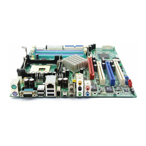
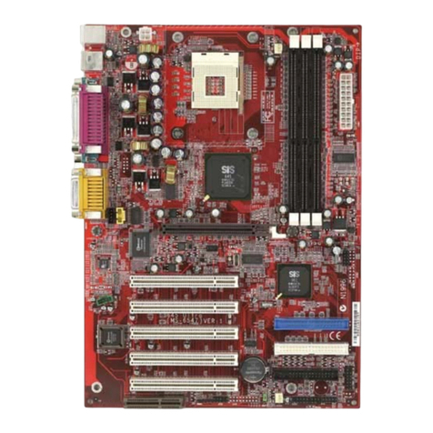
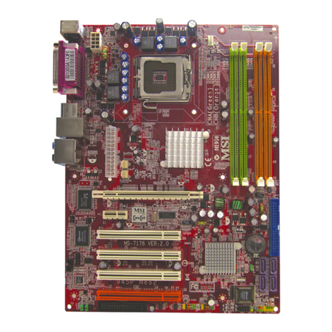
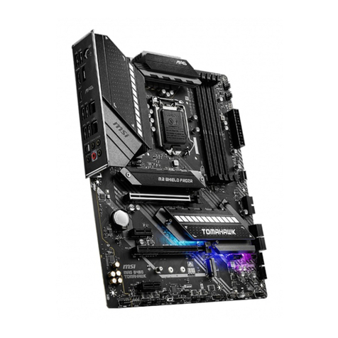
MSI 845PE-V2 Series User manual

i
FCC-B Radio Frequency Interference Statement
This equipment has been tested and found to comply with the limits for a class B digital device, pursuant to
part 15 of the FCC rules. These limits are designed to provide reasonable protection against harmful
interference when the equipment is operated in a commercial environment. This equipment generates, uses
and can radiate radio frequency energy and, if not installed and used in accordance with the instruction
manual, may cause harmful interference to radio communications. Operation of this equipment in a
residential area is likely to cause harmful interference, in which case the user will be required to correct the
interference at his own expense.
Notice 1
The changes or modifications not expressly approved by the party responsible for compliance could void the
user’s authority to operate the equipment.
Notice 2
Shielded interface cables and A.C. power cord, if any, must be used in order to comply with the emission
limits.
VOIR LANOTICE D’NSTALLATION AVANT DE RACCORDER AU RESEAU.
Micro-Star International
MS-7154
This device complies with Part 15 of the FCC Rules. Operation is subject to the following two conditions:
(1) this device may not cause harmful interference, and
(2) this device must accept any interference received, including interference that may cause undesired
operation
G52-M7154X1

ii
Copyright Notice
The material in this document is the intellectual property of MICRO-STAR INTERNATIONAL. We take every
care in the preparation of this document, but no guarantee is given as to the correctness of its contents. Our
products are under continual improvement and we reserve the right to make changes without notice.
Trademarks
All trademarks are the properties of their respective owners.
AMD, Athlon™ Athlon™XP, Thoroughbred™ and Duron™ are registered trademarks of AMD Corporation.
Intel® and Pentium® are registered trademarks of Intel Corporation.
PS/2 and OS® 2 are registered trademarks of International Business Machines Corporation.
Microsoft® is a registered trademark of Microsoft Corporation. Windows® 98/2000/NT/XP are registered
trademarks of Microsoft Corporation.
NVIDIA, the NVIDIA logo, DualNet, and nForce are registered trademarks or trademarks of NVIDIA
Corporation in the United States and/or other countries.
Netware® is a registered trademark of Novell, Inc.
Award® is a registered trademark of Phoenix Technologies Ltd.
AMI® is a registered trademark of American Megatrends Inc.
Kensington and MicroSaver are registered trademarks of the Kensington Technology Group.
PCMCIA and CardBus are registered trademarks of the Personal Computer Memory Card International
Association.
Revision History
Revision Revision History Date
V1.0 First release December 2004

iii
Safety Instructions
1. Always read the safety instructions carefully.
2. Keep this User Manual for future reference.
3. Keep this equipment away from humidity.
4. Lay this equipment on a reliable flat surface before setting it up.
5. The openings on the enclosure are for air convection hence protects the equipment from overheating.
Do not cover the openings.
6. Make sure the voltage of the power source and adjust properly 110/220V before connecting the
equipment to the power inlet.
7. Place the power cord such a way that people can not step on it. Do not place anything over the power
cord.
8. Always Unplug the Power Cord before inserting any add-on card or module.
9. All cautions and warnings on the equipment should be noted.
10. Never pour any liquid into the opening that could damage or cause electrical shock.
11. If any of the following situations arises, get the equipment checked by a service personnel:
- The power cord or plug is damaged.
- Liquid has penetrated into the equipment.
- The equipment has been exposed to moisture.
- The equipment does not work well or you can not get it work according to the User’ Manual.
- The equipment has dropped and damaged.
- The equipment has obvious sign of breakage.
12. Do not leave this equipment in an environment unconditioned, storage temperature above 60° C (140°F),
it may damage the equipment.

iv
Table of Contents
ENGLISH..................................................................1
简体中文...................................................................17

1
BATT
+
ICH4
D
D
R
2
D
D
R
1
JCD1
JFP2
JFP1
JBAT1
JPUSB1
JUSB1
JAUD1
JCI1
PWR1
SYS_FAN1
CPUFAN1
PCI Slot 2
PCI Slot 1
PCI Slot 3
PCI Slot 4
IDE1
I
D
E
2
Top: Parallel Port
Bottom:
COMA
Top: Mouse
Bottom: Keyboard
Top: LAN Jack
Bottom: USB
Ports
USB
Ports
Codec
JPW1
T: Line-In
M:
B: Mic
Line-Out
FDD 1
Winbond
W83627THF
Broadcom
BCM4401KQL
AGP Slot
Intel 845PE
BIOS
Introduction
Thank you for purchasing 845PE-V2Series (MS-7154) v1.X Micro ATX mainboard. The 845PE-V2
Series is based on Intel ®845PE & Intel ®ICH4 chipsets and provides 6USB 2.0 ports for high-speed
data transmission. With all these special designs, the 845PE-V2 Series delivers a high performance
and professional desktop platform solution.
Layout

2
Specifications
CPU
lSocket478forP4processors(Northwood/Prescott)at400MHz/533MHz/800MHz(800MHzfor
overclocking)
lSupportsupto3.4GHzorfaster.
(Forthelatest information aboutCPU,pleasevisit
http://www.msi.com.tw/program/products/mainboard/mbd/pro_mbd_cpu_support.php )
Chipset
lIntel 845PE
-SupportsFSB 400MHz/533MHz/800MHz(800MHzforoverclocking)
-SupportsDDR266/333/400(DDR400foroverclocking)technology.
lIntel ICH4
-AC97ControllerIntegrated.
-6portsHi-SpeedUSB 2.0controller,480Mb/sec.
-SupportsbothACPI and legacyAPMpowermanagement.
-Legacyfreesupport.
Main Memory
lSupports2memorybanksusingtwo184-pinunbuffered DDR266/333/400(DDR400for
overclocking)DIMMs.
lSupportsupto2GBmemorysizewithoutECC.
(Fortheupdatedsupportingmemorymodules,pleasevisit
http://www.msi.com.tw/program/products/mainboard/mbd/pro_mbd_trp_list.php )
Slots
lOneAGP(AcceleratedGraphics Port)slot that supportsAGP2.04X/2X.
lFourPCI2.232-bitMasterPCIBusslots(support3.3V/5VPCI businterface).
On-Board IDE
lDual IDEcontrollersintegrated in Intel ICH4.
lSupportsBusMaster, UltraDMA33/66/100operation modes.
lCanconnectuptofourIDEdevices.
On-BoardPeripherals
lOn-BoardPeripheralsincludes:

3
-1floppyportsupports1FDD with360K,720K,1.2M,1.44Mand 2.88Mbytes.
-1serialport (COMA)
-1parallel portsupportsSPP/EPP/ECPmode
-6USB2.0/1.1ports(Rear*4/ Front *2)
-1Line-In/Line-Out/Mic-Inport
-1RJ-45LANconnector
Audio
lAC97linkcontrollerintegratedinIntel ICH4.
l6channelsS/WaudiocodecAD1888codec
-CompliancewithAC972.2Spec
-MeetsPC2001audioperformancerequirement
LAN
lBroadcom4401PCI2.2LAN
-Supports10Mb/sand100Mb/sauto-negotiation operations.
-CompliancewithPCI2.2andPC99standard.
BIOS
l2MBAwardBIOSwithPNPBIOS,ACPI, SMBIOS2.3, GreenandBoot Block.
lProvidesDMI2.0, WFM2.0,WOL, chassisintrusion,andSMBusforsystemmanagement.
Dimension
lATXFormFactor:30.5cm(L)x17.5cm(W).
Mounting
l6mountingholes.

4
Rear Panel
The backpanelprovidesthefollowing connectors:
HardwareSetup
ThischaptertellsyouhowtoinstalltheCPU, memorymodules,andexpansioncards,aswellashowto
setupthejumpersonthemainboard. Italsoprovidestheinstructionson connectingtheperipheral
devices,suchasthemouse, keyboard,etc. Whiledoingtheinstallation,becareful in holdingthe
componentsandfollowtheinstallationprocedures.
Central ProcessingUnit: CPU
The mainboardsupportsIntel Pentium4Northwood&Prescott Celeron processorinthe478pin
package.ThemainboardusesaCPUsocketcalled PGA478foreasyCPUinstallation. Whenyouare
installingtheCPU, makesuretheCPUhasaheatsinkandacoolingfanattachedonthetoptoprevent
overheating.If you donot findtheheat sinkandcoolingfan, contactyourdealertopurchaseand install
thembeforeturningonthecomputer. (Forthelatestinformationabout CPU,pleasevisit
http://www.msi.com.tw/program/products/mainboard/mbd/pro_mbd_cpu_support.php )
ExampleofCPUCore Speed Derivation Procedure
IfCPUClock=133MHz
Core/Busratio =23
thenCPUcorespeed=Host ClockxCore/Busratio
=133MHzx23
=3.06 GHz

5
Memory Speed/CPUFSBSupportMatrix
Memory
FSB DDR 266 DDR 333 DDR 400*
400MHz OK OK OK
533MHz OK OK OK
800MHz* OK OK OK
*Foroverclockingonly.
MSIRemindsYou...
Overheating
Overheatingwill seriouslydamagethe CPUandsystem,always makesurethe coolingfancanwork
properlytoprotect the CPUfromoverheating.
Replacing theCPU
WhilereplacingtheCPU,always turnoff the ATXpowersupplyorunplugthepowersupply’spower
cordfromgroundedoutlet first toensurethesafetyof CPU.
CPUInstallation Procedures forSocket478
1.Pleaseturnoffthepowerandunplug thepowercordbeforeinstallingtheCPU.
2.Pulltheleversidewaysawayfromthesocket.Makesuretoraisetheleveruptoa90-degree
angle.
3.Lookforthegoldarrow.Thegoldarrowshouldpointtowardstheleverpivot. TheCPUcan only
fit in thecorrectorientation.
4.IftheCPUiscorrectlyinstalled, thepinsshouldbecompletelyembedded intothesocketand
can notbeseen.Pleasenotethatanyviolation of thecorrectinstallationproceduresmaycause
permanentdamagestoyourmainboard.
5.Press theCPUdownfirmlyintothesocket and closethelever.Asthe CPUislikelytomove
whiletheleverisbeing closed,alwaysclosetheleverwithyourfingerspressingtightlyontop of
theCPUtomakesuretheCPUisproperlyandcompletelyembeddedintothesocket.

6
InstallingtheCPUFan
Asprocessortechnologypushestofasterspeedsandhigherperformance, thermal management
becomesincreasinglyimportant.Todissipateheat,youneedtoattachtheCPUcoolingfanand
heatsinkon top oftheCPU.FollowtheinstructionsbelowtoinstalltheHeatsink/Fan:
1.LocatetheCPUand itsretention mechanismon themotherboard.
2.Positiontheheatsinkontotheretention mechanism.
3.Mount thefan on top oftheheatsink. Press downthefanuntilitsfourclipsgetwedged inthe
holesoftheretentionmechanism.
4.Press thetwoleversdowntofasten thefan. Eachlevercanbepressed downin onlyONE
direction.
5.Connectthefanpowercablefromthemounted fantothe3-pinfan powerconnectoron the
board.
Memory
Themainboardprovidestwo184-pin unbuffered DDR266/DDR333/DDR400SDRAM,andsupportsthe
memorysizeup to2GB.Tooperateproperly,atleastoneDIMMmodulemustbeinstalled. (Forthe
updatedsupportingmemorymodules,pleasevisit
http://www.msi.com.tw/program/products/mainboard/mbd/pro_mbd_trp_list.php )
Installat least oneDIMMmoduleon theslots.Memorymodulescan beinstalled ontheslotsinany
order.You can install eithersingle-ordouble-sided modulestomeetyourownneeds.
Installing DDRModules
1.The DDR DIMMhasonlyonenotchonthecenterof module.Themodulewillonlyfitintheright
orientation.
2.InserttheDIMMmemorymoduleverticallyintotheDIMMslot.Then pushitinuntilthegolden
fingeron thememorymoduleisdeeplyinserted inthesocket.
3.The plasticclipat eachsideoftheDIMMslot willautomaticallyclose.

7
NotchVolt
Power Supply
The mainboardsupportsATXpowersupplyforthepowersystem.Beforeinsertingthepowersupply
connector,alwaysmakesurethatall componentsareinstalled properlytoensurethatnodamagewill
becaused.A300Worabovepowersupplyissuggested.
ATX20-PinPower Connector:PWR1
Thisconnectorallowsyoutoconnecttoan ATXpowersupply.To
connect totheATXpowersupply,makesuretheplugofthepower
supplyisinsertedintheproperorientationand thepinsarealigned.
Then pushdownthepowersupplyfirmlyintotheconnector.
ATX12VPower Connector:JPW1
This12Vpowerconnectorisused toprovidepowertotheCPU.
1
3
2
4
GND
GND
12V 12V
FloppyDisk DriveConnector:FDD1
The mainboardprovidesastandardfloppydisk driveconnector
that supports360K, 720K,1.2M, 1.44Mand2.88Mfloppydisk
types.
ChassisIntrusionSwitch Connector:JCI1
Thisconnectorisconnected to2-pinconnectorchassisswitch. Ifthe
Chassisisopen, theswitchwillbeshort.Thesystemwillrecordthisstatus.Toclearthewarning,you
3.3V
-12V
GND
GND
PW_OK -5V
5V_SB 5V
12V
PS_ON
10
20
11
1
GND
GND
5V
GND
GND
GND
5V
5V
3.3V
3.3V
2
1GND
CINTRO

8
mustentertheBIOSsettingandclearthestatus.
CD-In Connector:JCD1
The connectorisforCD-ROMaudioconnector.
FanPower Connectors:CPUFAN1/SYS_FAN1
The CPUFAN1(processorfan)andSYS_FAN1(systemfan)supportsystem
coolingfanwith+12V.Theysupportthree-pinheadconnector.When connecting
thewiretotheconnectors,alwaystakenotethat thered wireisthepositiveand
should beconnected tothe+12V,theblackwireisGroundand shouldbe
connectedtoGND.IfthemainboardhasaSystemHardwareMonitorchipseton-board, youmustusea
speciallydesignedfan withspeedsensortotakeadvantageof theCPUfan control.
MSIRemindsYou...
1.Always consultthevendorsforproperCPUcoolingfan.
2. CPUFAN1supportsthefancontrol.Youcaninstall the PCAlertutilitythatwill automaticallycontrol
theCPUfanspeedaccordingtotheactualCPUtemperature.
IDEConnectors:IDE1&IDE2
Themainboardhasa32-bit Enhanced PCI IDEandUltraDMA33/66/100/133 controllerthat
providesPIOmode0~4,BusMaster,andUltraDMA33/66/100/133function. Youcan
connectup tofourharddisk drives, CD-ROM,120MBFloppyandotherdevices.
The first harddriveshouldalwaysbeconnected toIDE1.IDE1can connectaMasteranda
Slavedrive.You must configuresecondharddrivetoSlavemodebysetting thejumper
accordingly.IDE2can alsoconnectaMasterandaSlavedrive.
MSIRemindsYou...
If youinstall twoharddisks on cable,youmust configuretheseconddrivetoSlavemodebysettingits
jumper. Refertotheharddisk documentation suppliedbyharddisk vendorsforjumpersetting
instructions.
GND
L
R

9
FrontPanel Connectors:JFP1&JFP2
The mainboardprovidestwofrontpanel connectorsforelectrical
connection tothefront panel switchesandLEDs. JFP1iscompliant
withIntel Front Panel I/OConnectivityDesignGuide.
FrontPanelAudio Connector:JAUD1
The JAUD1frontpanel audioconnectorallowsyoutoconnect tothe
front panel audioandiscompliantwithIntel Front Panel I/O
ConnectivityDesignGuide.
MSIRemindsYou...
If youdonot want toconnect tothe frontaudio header,pins5&6, 9&10havetobe jumpered inorder
tohavesignaloutput directedtothe rearaudioports. Otherwise,theLine-Out connectorontheback
panelwillnotfunction. 1
2
9
10
FrontUSBConnector:JUSB1
The mainboardprovidesonestandardUSB2.0pinheaderJUSB1. USB
2.0technologyincreasesdatatransferrateuptoamaximumthroughput
of 480Mbps,whichis40 timesfasterthan USB1.1, and isideal for
connecting high-speedUSB interfaceperipheralssuchasUSBHDD,digital cameras,MP3players,
printers,modemsandthelike.
MSI RemindsYou...
Pleasenotethat thepinsof VCC&GNDmustbe connected correctly, oritmaycausesomedamage
Keyboard/Mouse VoltageJumper:JPUSB1
Thisjumperisused forsettingthevoltageofthekeyboard/mouse.Thedefault settingisVCC5(1~2).
VCC55VStandby

10
Clear CMOSJumper:JBAT1
ThereisaCMOSRAMon boardthathasapowersupplyfromexternal batterytokeepthedataof
systemconfiguration.WiththeCMOSRAM,thesystemcan automaticallyboot OSeverytimeitis
turnedon.If you want toclearthesystemconfiguration,usetheJBAT1(ClearCMOSJumper) toclear
data. Followtheinstructionsbelowtoclearthedata:
1 1
3
KeepData ClearData
1
3
MSIRemindsYou...
You can clearCMOSbyshorting 2-3pin whilethesystemisoff.Then returnto1-2pin position.Avoid
clearingtheCMOSwhilethesystemison;it willdamage themainboard.
AGP(Accelerated Graphics Port) Slot
The AGPslotallowsyoutoinserttheAGPgraphicscard.AGPisaninterfacespecificationdesigned for
thethroughputdemandsof3Dgraphics. It introducesa66MHz,32-bit channelforthegraphics
controllertodirectlyaccess mainmemory.Themainboardsupports2x/4x1.5VAGPcard.
PCI (PeripheralComponentInterconnect) Slots
The PCIslotsallowyoutoinsert theexpansion cardstomeetyourneeds. Whenaddingorremoving
expansioncards, makesurethat youunplugthepowersupplyfirst.Meanwhile,readthedocumentation
fortheexpansion cardtomakeanynecessaryhardwareorsoftwaresettingsfortheexpansioncard,
suchasjumpers, switchesorBIOSconfiguration.

11
PCI InterruptRequestRouting
The IRQ,abbreviation of interrupt requestlineandpronouncedI-R-Q,arehardwarelinesoverwhich
devicescan sendinterrupt signalstothemicroprocessor.ThePCIIRQpinsaretypicallyconnected to
thePCIbusINTA#~INT D#pinsasfollows:
Order1 Order2 Order3 Order4
PCISlot 1 INTB# INTC# INTD# INTA#
PCISlot 2 INTC# INTD# INTA# INTB#
PCISlot 3 INTD# INTA# INTB# INTC#
PCISlot 4 INTB# INTC# INTD# INTA#

12
BIOSSetup
Poweron thecomputerandthesystemwillstart POST (PowerOnSelfTest)process.When the
messagebelowappearson thescreen,press <DEL>keytoenterSetup.
DEL:Setup
Ifthemessagedisappearsbeforeyourespondand you stillwishtoenterSetup, restartthesystemby
turningit OFFandOnorpressingtheRESETbutton.You mayalsorestart thesystemby
simultaneouslypressing <Ctrl>,<Alt>,and<Delete> keys.
MainPage
Standard CMOSFeatures
Usethismenuforbasicsystemconfigurations, suchastime, dateetc.
Advanced BIOSFeatures
UsethismenutosetuptheitemsofAwardspecial enhancedfeatures.
AdvancedChipsetFeatures
Usethismenutochangethevaluesin thechipset registersandoptimizeyoursystemperformance.
IntegratedPeripherals
Usethismenutospecifyyoursettingsforintegrated peripherals.
PowerManagementSetup
Usethismenutospecifyyoursettingsforpowermanagement.
PNP/PCIConfigurations
Thisentryappearsif yoursystemsupportsPnP/PCI.
H/W Monitor
Thisentryshowsyourhardware&PChealthstatus.

13
Frequency/VoltageControl
Usethismenutospecifyyoursettingsforfrequency/voltagecontrol.
Load Fail-SafeDefaults
UsethismenutoloadtheBIOSvaluesforthebestsystemperformance,but thesystemstabilitymay
beaffected.
LoadOptimizedDefaults
Usethismenutoloadthedefault valuesset bythemainboardmanufacturerspecificallyforoptimal
performanceof themainboard.
BIOSSettingPassword
Usethismenutoset BIOSsetting Password.
Save&ExitSetup
SavechangestoCMOSandexit setup.
ExitWithoutSaving
Abandonall changesand exitsetup.

14
Frequency/VoltageControl
CurrentCPUClock
It showsthecurrent clockofCPU. Read-only.
AdjustMemoryFrequency
Whenit isset to[Manual] inHighPerformanceMode,usercanplacean artificialmemoryclocklimiton
thesystem.Pleasenotethatmemoryisprevented fromrunningfasterthan thisfrequency. Setting
options: [PC100], [PC133], [Auto].
AutoDetectPCI Clk
Thisitemisused toautodetectthePCI slots.When setto[Enabled], thesystemwill remove(turnoff)
clocksfromemptyPCIslotstominimizetheelectromagneticinterference(EMI). Settings: [Enabled],
[Disabled].
SpreadSpectrum
Whenthemotherboard’sclockgeneratorpulses, theextremevalues(spikes)ofthepulsescreatesEMI
(ElectromagneticInterference).TheSpreadSpectrumfunction reducestheEMIgenerated by
modulating thepulsessothat thespikesofthepulsesarereduced toflattercurves.If you donothave
anyEMIproblem,leavethesettingat [Disabled]foroptimal systemstabilityandperformance. Butifyou
areplagued byEMI,select thedesired rangeforEMI reduction. RemembertodisableSpread
Spectrumfunction if you areoverclocking,becauseevenaslight jittercan introduceatemporaryboost
in clockspeed whichmayjust causeyouroverclockedprocessortolockup.
CPUClock
Thisitemallowsyou toselecttheCPUFront SideBusclockfrequency(inMHz)andoverclockthe

15
processorbyadjustingtheFSB clock toahigherfrequency.
AdjustCPURatio
Thisitemallowsyou toadjusttheCPUratio. Settingrangeisfrom[8]to[50].
MemoryVoltage
Adjusting theDDR voltagecanincreasetheDDR speed. However,anychangesmadetothissetting
maycauseastabilityissue, so changing theDDR voltageforlong-termpurposeisNOT
recommended.
AGPVoltage
AGPvoltageisadjustableinthefield,allowing you toincreasetheperformanceof yourAGPdisplay
cardwhen overclocking, butthestabilitymaybeaffected. Settingoptions:1.5Vto1.8Vat0.1V
increment.

16
Load Optimized Default
You can load theBIOSoptimized default valuesprovided bythemainboardmanufacturerforthestable
performance.
This manual suits for next models
1
Table of contents
Other MSI Motherboard manuals

MSI
MSI B550M PRO User manual

MSI
MSI 848P-V2 Series User manual

MSI
MSI MS-9641 User manual

MSI
MSI Z77IA-S01 Series User manual

MSI
MSI 945GCM5 Series User manual

MSI
MSI MPG Z490 GAMING PLUS User manual

MSI
MSI B360M PRO-VD User manual

MSI
MSI MS-7551 User manual

MSI
MSI 870A Fuzion Power Edition series User manual

MSI
MSI MPG Z790 CARBON WIFI User manual