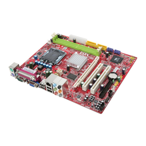
MSI J-TX98 R2 User manual

Chapter 1
1-1 Preface.....................................................................................................1
1-2 Key Feature.............................................................................................1
Chapter 2
Hardware Installation..........................................................................................2
2-1 Unpacking...............................................................................................2
2-2 ainboard Layout...................................................................................3
2-3 Quick Reference for Jumpers, Connectors & Expansion Socket.....4
2-4 Installation Steps....................................................................................5
2-5 Jumper Settings.....................................................................................5
2-6 System emory (DRA )........................................................................10
2-7 Central Processing Unit (CPU)..............................................................10
2-8 Expansion Cards....................................................................................11
2-9 External Connectors..............................................................................12
Chapter 3
AWARD BIOS SETUP..........................................................................................18
3-1 STANDARD C OS SETUP.....................................................................19
3-2 BIOS FEATURES SETUP.......................................................................20
3-3 CHIPSET FEATURES SETUP................................................................24
3-4 POWER ANAGE ENT SETUP............................................................26
3-4-1 The Description of the Power anagement.............................27
3-5 PNP/PCI CONFIGURATION SETUP........................................................29
3-6 LOAD BIOS DEFAULTS..........................................................................30
3-7 LOAD SETUP DEFAULTS.......................................................................30
3-8 INTEGRATED PERIPHERALS SETUP...................................................31
3-9 SUPERVISOR/USER PASSWORD..........................................................34
3-10 IDE HDD AUTO DETECTION.................................................................35
3-11 SAVE & EXIT SETUP.............................................................................37
3-12 EXIT WITHOUT SAVING........................................................................37
3-13 I/O & E ORY AP..............................................................................37
3-14 TI E & D A CHANNELS AP.............................................................39
3-15 INTERRUPT AP...................................................................................39
3-16 BIOS REFERENCE-POST CODES........................................................40
Chapter 4
Software Installed...............................................................................................44
Chapter 5
Question and Answer.........................................................................................46
i
TABLE OF CONTENT

Chapter 1
1-1 Preface
Welcome to use the J-TX98 R2 mainboard. This mainboard is support Pentium
processor PC/AT compatible s stem with ISA bus and PCI local bus. Also for this
board including some special designs like share memor VGA on-board,
ACPI/AMP power management & powerful performance and so on. We think ou
will enjo ing our personal computer because of our right choice.
1-2 Key Feature
Chip set: SiS 5598 PCI/ISA with built-in VGA single chip.
Support Processor: Running at 75~300MHz CPU on a ZIF Socket 7. Support
Intel Pentium processor/Intel Pentium processor with MMX technolog ;
AMD-K5/AMD-K6; C rix/IBM 6X86/6X86L/6X86MX & IDT C6 CPU.
L2 Cache: Provides on board 256K/512K Pipelined Burst SRAM to increase
s stem performance.
emory expansion: Support 3 Banks of DRAM from 8MB to 384MB, and
supports all kind of D-RAM t pe including FAST PAGE D-RAM, E.D.O. D-
RAM and S nchronous D-RAM.
ISA and PCI expansion Slots: Provides three 16-bits ISA & three 32-bits
PCI slots.
PCI Bus aster IDE Controller: On-board ULTRA DMA-33 bus master IDE
controller with two connectors that supports four IDE devices in two channel,
provide faster data transfer rate up to 33MB/sec. This controller supports PIO
mode 3 and 4 and Bus Master IDE DMA.
Super ULTI-I/O: Provide two high-speed UART compatible serial ports and
one extra PS/2 mouse cable including, one parallel port with EPP and ECP
capabilities. Two flopp drives of either 5.25” or 3.5” (1.44MB or 2.88MB) and
also supported without an external card.
USB IrDA Connector: This board supports two USB ports connector and
one infrared port module connector for wireless interface. (The cable connect
to two USB ports and the infrared module is optional parts.)
Built-In High performance VGA:
Built-in VGA memor selected b BIOS setup from 1MB to 4MB
64 bits displa memor path
Support 170MHz pixel clock
Support full motion video pla back required onl 1MB DRAM and up to
1024x768x256 color Mode
Support DCI, Direct Draw, Direct MPEG, Microsoft Video to improve pla
back qualit
Support high resolution graphic modes
1

Chapter 2
Hardware Installation
2-1 Unpacking
This mainboard package should contain the following:
The J-TX98 R2 mainboard
USER’S MANUAL for mainboard
Cable set for IDE x1, Flopp x1, COM1 & COM2 x1, LPT & PS/2 Mouse x1,
VGA x1
CD for Drivers PACK
The mainboard contains sensitive electronic components which can be easil
damaged b electron-static, so the mainboard should be left in its original packing
until it is installed.
Unpacking and installation should be done on a grounded anti-static mat.
The operator should be wearing an anti static wristband, grounded at the same
point as the anti-static mat.
Inspect the mainboard carton for obvious damage. Shipping and handling ma
cause damage to our board. Be sure there are no shipping and handling damages
on the board before proceeding.
After opening the mainboard carton, extract the s stem board and place it onl on
a grounded anti-static surface component side up. Again inspect the board for
damage.
Press down on all of the socket IC’s to make sure that the are properl inserted.
Do this onl on with the board placed on a firm flat surface.
Warning: Do not apply power to the board if it has been damaged.
You are now read to install our mainboard. The mounting hole pattern on the
mainboard matches the IBM-AT s stem board.
It is assumed that the chassis is designed for a standard IBM XT/AT main
board mounting. Place the chassis on the anti-static mat and remove the cover.
Take the plastic clips, N lon stand-off and screws for mounting the s stem board,
and keep them separate.
2

2-2 ainboard Layout
Figure 2-1
2-3 Quick Reference for Jumpers, Connectors &
3

Expansion Socket
Jumpers
Jumper Name Description Page
JP17 CMOS RAM Clear 1-2 Normal
2-3 Clear CMOS p. 9
JP19 FLASH ROM Voltage setting 1-2 12V FLASH ROM
2-3 5V FLASH ROM p. 5
JP15 CPU Voltage selector for detail page 6 p. 6
SW1 DIP switch for CPU t pe selection for detail page 6 p. 6
JP1,JP2,JP10 Internal VGA function selection for detail page 9 p. 9
Connectors
Connector Name Description Page
J4 Ke board Connector 5-Pins Female p.13
USB1 USB Port Connector 10-Pins Block p.16
J1 PS/2 Mouse Connector 6-Pins Block p.13
COM1,COM2 Serial Port COMA & COMB 10-Pins Block p.14
LPT1 Parallel Port Connector 26-Pins Block p.13
FDD1 Flopp Driver Connector 34-Pins Block p.14
IDE1 Primar IDE Connector 40-Pins Block p.14
IDE2 Secondar IDE Connector 40-Pins Block p.15
J5 VGA Connector 16-Pins Block p.17
J9 CPU FAN Connector 1-2 12V Power Connector
2-3 ACPI FAN power control
Connector
p.17
IR Infrared Module Connector 5-Pins Block p.16
PW1 AT Power Connector 12-Pins Block p.12
PW2 ATX Power Connector 20-Pins Block p.12
FPC Front Panel Connector 16-Pins Block p.15
HDLED IDE activit LED 2-Pins Connector p.15
PS-ON ATX power button/soft power
button
4-Pins connector p.17
Expansion Sockets
4

Socket/Slot Name Description Page
SL1, SL3, SL5 ISA Slot 16-bits ISA Bus Expansion slots p.11
PCI1, PCI2, PCI3 PCI Slot 32-bits PCI Local Bus Expansion
slots
p.11
SIMM1, SIMM2 SIMM Module Socket 72-Pins SIMM D-RAM Module
Expansion Socket
p.10
SDRAM1, SDRAM2 DIMM Module Socket 168-Pins DIMM SDRAM Module
Expansion Socket
p.10
ZIF SOCKET 7 CPU Socket Pentium CPU Socket p.10
2-4 Installation Steps
Before using our computer, ou must follow the steps as follows:
1. Set Jumpers on the Motherboard
2. Install the CPU
3. Install DRAM Modules
4. Install Expansion card
5. Connect Cables, Wires, and Power Suppl
2-5 Jumper Settings
1. Flash RO Voltage Selection: JP19 (Yellow color selector)
This jumper set the voltage supplied to the Flash ROM. It depend on Flash
ROM Brand, for this jumper will be setted b factor , ou don’t need to
change this jumper b ourself.
Programming JP19
+12V 1-2 (Intel, MXIC)
+5V 2-3 (SST, Winbond, Atmel)
+12V
+5V
JP19
1
3
2
JP19
1
3
2
Flash RO Voltage Selection
2. CPU Voltage Selection: JP15 (Yellow color selector)
5

This jumper is used for adjusting CPU working voltage, for this main board
design it can auto detect the single voltage CPU or dual voltage CPU.
The table of JP15 CPU voltage selection (O: open, S: short)
CPU TYPE Voltage 1-2 3-4 5-6 7-8 Default
Intel Pentium processor Voltage P54VRE
AMD single Voltage K5
C rix/IBM single Voltage 6X86
IDT-C6 150/180/200 3.52V S S S S
Intel Pentium processor Voltage P54STD 3.45V O S S S
AMD K6-PR233 Dual Voltage K6-PR233 3.2V O O S S
AMD K6-PR166 Dual Voltage K6-PR166/200
C rix/IBM 6X86MX -166, -200 Dual Voltage
(MX 166/200)
2.9V S O O S
C rix/IBM 6X86L 166+ Dual Voltage 6X86L 166+
Intel Pentium processor with MMX technolog
Dual Voltage (166/200/233)
2.8V O O O S *
AMD K6-PR233 Dual Voltage K6-PR233 2.2V O S O O
If your PU Type is not including in above table, please refer to the PU voltage
selection on below to choose the correct working voltage for your PU.
3. CPU Type selection: SW1 (6-Pins DIP Switch)
This mainboard design use 6-pins DIP switch to select the CPU, external
clock frequenc & Bus frequenc ratio, and the external clock frequenc
multiplied b Bus frequenc ratio is the CPU frequenc as the tables below:
Table for CPU external clock frequenc
DIP SWITCH
1
DIP SWITCH
2
DIP SWITCH
3
External clock
frequency
ON ON ON 50MHz
ON ON OFF 55MHz
OFF ON ON 60MHz
ON OFF ON 66.6MHz
Table for Bus frequenc Clock Ratio
DIP SWITCH DIP SWITCH DIP SWITCH Clock Ratio
6

4 5 6
OFF OFF OFF 1.5
ON OFF OFF 2.0
ON ON OFF 2.5
OFF ON OFF 3.0
OFF OFF OFF 3.5
ON OFF ON 4.0
ON ON ON 4.5
Table for CPU Type selection ( : ON, : OFF)
CPU Type
DIP Switch
Setting
DIP Switch (1,2,3)
External
clock frequency
DIP Switch (4,5,6)
Clock Ratio
External clock
frequency Ratio
= CPU frequency
75MHz Pentium processor
AMD K5-75MHz
ON
1
2
3
4
5
6
50MHz 1.5 75MHz
C rix/IBM 6X86-120+
ON
1
2
3
4
5
6
50MHz 2100MHz
C6-150MHz
ON
1
2
3
4
5
6
50MHz 3150MHz
C rix/IBM 6X86-133+
ON
1
2
3
4
5
6
55MHz 2110MHz
90MHz Pentium processor
AMD K5-PR90
ON
1
2
3
4
5
6
60MHz 1.5 90MHz
120MHz Pentium processor
C rix/IBM 6X86-150+
ON
1
2
3
4
5
6
60MHz 2 120MHz
150MHz Pentium processor
C rix/IBM 6X86MX-PR166
ON
1
2
3
4
5
6
60MHz 2.5 150MHz
C6-180MHz
ON
1
2
3
4
5
6
60MHz 3 180MHz
CPU Type
DIP Switch
Setting
DIP Switch (1,2,3)
External
clock frequency
DIP Switch (4,5,6)
Clock Ratio
External clock
frequency Ratio
= CPU frequency
7

100MHz Pentium processor
AMD K5-PR100
AMD K5-PR133
ON
1
2
3
4
5
6
66MHz 1.5 100MHz
133MHz Pentium processor
C rix/IBM 6X86-166+
ON
1
2
3
4
5
6
66MHz 2 133MHz
166MHz Pentium processor
with MMX technolog
C rix 6X86MX-PR166
AMD K5-PR166
AMD K6-PR166
ON
1
2
3
4
5
6
66MHz 2.5 166MHz
200MHz Pentium processor
with MMX technolog
C rix 6X86MX-PR233
AMD K6-PR200
C6-200MHz
ON
1
2
3
4
5
6
66MHz 3 200MHz
233MHz Pentium processor
with MMX technolog
AMD K6-PR2-233
ON
1
2
3
4
5
6
66MHz 3.5 233MHz
AMD K6-PR2-266
ON
1
2
3
4
5
6
66MHz 4 266MHz
AMD K6-PR2-300
ON
1
2
3
4
5
6
66MHz 4.5 300MHz
NOTE:
Before installing the PU, Please check the PU Frequency and lock
Ratio from your supplier.
For yrix/IBM 6X86MX series, please double check the PU’s Frequency
and lock Ratio.
75MHz/83.3MHz PU’s Bus Frequency is not in the reqular specification,
therefore, we do not recommend to use it.
DIP Switch for CPU Type
SW1
ON
1
2
3
4
5
6
4. C OS RA Clear: JP17 (Yellow color selector)
8

WARNING: Make sure your computer is POWER OFF when you LEAR MOS.
Connect a jumper Cap over this jumper for a few seconds, will clears
information stored in the CMOS RAM Chip that input b user, such as hard
disk information and passwords. After CLEAR CMOS, ou must enter the
BIOS setup (b holding down <DEL> during power-up) to re-enter BIOS
information (see BIOS SETUP).
Selections JP17
Normal 1-2 (Default)
Clear CMOS 2-3 (momentaril )
Normal
C OS RA (Normal / Clear C OS Data)
JP17
1
2
3
Clear C OS
JP17
1
2
3
5. Internal VGA function Selection: JP1, JP2, JP10
Selections JP1 JP2 JP10
Enabled 1-2 1-2 2-3
Disabled 2-3 2-3 1-2
Internal VGA function Selection
JP10
1
2
3
Enabled
JP1
1
2
3
JP2
Disabled
JP1
1
2
3
JP2
JP10
1
2
3
2-6 System emory (DRA )
9

This main board can be installed with 72 pin SIMM module DRAM, or 168 pins
DIMM module s nchronous DRAM. The DRAM memor s stem on main board
can support BANK 0, BANK 1, BANK 2, for 72 pin SIMM socket was defined to be
BANK 0, or BANK2 and SDRAM1 & SDRAM2 to be BANK 0 & BANK 1.
Because of the 72-pins SIMM module is 32 bits width using 2 pcs which can
match a 64 bits pentium s stem.
Install DRAM on this main board please reference the table below.
JP11 2-3 closed
JP12 2-3 closed
JP11 1-2 closed
JP12 1-2 closed SDRA 1 SDRA 2 System can be
SI 1, SI 2
BANK 0
SI 1, SI 2
BANK 2
BANK 0 BANK 1 Accept or not
72 Pin FPM
or EDO SIMM
Accept
72 Pin FPM
or EDO SIMM
Not Accept
168 Pin S-DRAM
DIMM
Accept
168 Pin S-DRAM
DIMM
Not Accept
72 Pin FPM
or EDO SIMM
168 Pin S-DRAM
DIMM
Not Accept
72 Pin FPM
or EDO SIMM
168 Pin S-DRAM
DIMM
Accept
72 Pin FPM
or EDO SIMM
168 Pin S-DRAM
DIMM
168 Pin S-DRAM
DIMM
Not Accept
72 Pin FPM
or EDO SIMM
168 Pin S-DRAM
DIMM
168 Pin S-DRAM
DIMM
Accept
168 Pin S-DRAM
DIMM
168 Pin S-DRAM
DIMM
Accept
72 Pin FPM
or EDO SIMM
168 Pin S-DRAM
DIMM
Accept
JP11 2-3 closed, JP12 2-3 closed (Default setting) for BANK 0.
Because of Share memory the system must occupy BANK 0 to booting.
2-7 Central Processing Unit (CPU)
The main board provides a 321-pins ZIF Socket 7. The CPU on mother board
must have a fan attached to prevent overheating.
WARNING: Without a fan, the PU will be overheated and cause damage to both the
PU and the motherboard.
To install a CPU, first turn off our s stem and remove its cover. Locate the ZIF
socket and open it b first pulling the lever sidewa s awa from the socket then
upwards to a 90-degree right angle. Insert the CPU with the white dot as our
10

guide. The white dot should point towards the end of the level. The CPU has a
corner pin for three of the four corners, the CPU will onl fit in the one orientation
as shown as follow. With the added weight of the CPU fan, no force is required to
insert the CPU. Once completel inserted, hold down on the fan and close the
socket’s lever.
IMPORTANT: You must set jumpers SW1 “DIP Switch for PU Type” on page 6 and
jumper JP15 “ PU Voltage Selection” on page 6 depending on the PU that
you install.
Socket 7
Lever
White Dot
Lock
Socket 7
Blank
CPU ZIF Socket 7
CPU
2-8 Expansion Cards
First read our expansion card documentation on an hardware and software
settings that ma be required to setup our specific card.
Installation Procedure:
1. Read the documentation for our expansion card.
2. Set an necessar jumpers on our expansion card.
3. Remove our computer’s cover.
4. Remove the bracket on the slot ou intend to use.
5. Carefull align the card’s connectors and press firml .
6. Secure the card on the slot with the screw ou remove in step 4.
7. Replace the computer’s cover.
8. Setup the BIOS if necessar .
9. Install the necessar software drivers for our expansion card.
2-9 External Connectors
1. Power connector: AT Power Connector (12-pins block): PW1
11

This connector connects to a standard AT power suppl . To connect the leads
from the power suppl , ensure first that the power suppl is not plugged. Most
power supplies provide two plugs (P8 and P9), each containing six wires, two
of which are black. Orient the connectors so that the black wires are located
in the middle.
Using a slight angle, align the plastic guide pins on the lead to their receptacles
on the connector. Once aligned, press the lead onto the connector until the
lead locks into place.
Power Plugs from Power Supply
Power Connector on otherboard
PG
+12V
GND
+5V
-12V
-5V
+5V
P8
P9
ORG
RED
YLW
BLU
BLK
BLK
BLK
BLK
WHT
RED
RED
RED
2. Power Connector: ATX Power Connector (20-pins block): PW2
ATX Power Suppl connector. This is a new defined 20-pins connector that
usuall comes with ATX case. The ATX Power Suppl allows to use soft
power on momentar switch that connect from the front panel switch to 2-pins
Power On jumper pole on the motherboard. When the power switch on the
back of the ATX power suppl turned on, the full power will not come into the
s stem board until the front panel switch is momentaril pressed. Press this
switch again will turn off the power to the s stem board.
PIN
ROW2
ROW1
1
3.3V
3.3V
2
-12V
3.3V
3
GND
GND
4
Soft Power On
5V
5
GND
GND
6
GND
5V
7
GND
GND
8
-5V
Power OK
9
+5V
+5V (for Soft Logic)
10
+5V
+12V
ATX Power Connector
Pin 1
3. Keyboard Connector (5-pins female): J4
This connection is for a standard IBM-compatible ke board. Ma also be
known as a 101 enhanced ke board.
12

4. PS/2 ouse Connector (6-pins block): J1
If ou are using a PS/2 mouse, ou must purchase an optional PS/2 mouse
set which connects to the 6-pins block and mounts to an open slot on our
computer‘s case.
1: DATA
2: NC
3: GND
4: VCC
5: CLK
6: NC
PIN 1
PS/2 ouse odule Connector
5. Parallel Printer Connector (26-pins Block): LPT1
Connection for the enclosed parallel port ribbon cable with mounting bracket.
Connect the ribbon cable to this connection and mount the bracket to the
case on an open slot. It will then be available for a parallel printer cable.
NOTE: Serial printers must be connected to the serial port. You can enable the parallel port
and choose the IRQ through BIOS Setup.
Pin 1
Parallel Printer Connector
LPT1
6. Serial port CO A and CO B Connector (Two 10-pins blocks): CO 1, CO 2
These connectors support the provided serial port ribbon cables with mounting
bracket. Connect the ribbon cables to these connectors and mount the
bracket to the case on an open slot. The two serial ports on the mounting
13

bracket will then be used for pointing devices or other serial devices. See
BIOS configuration of “Onboard Serial Port”
CO 2
Pin 1
Pin 1
CO 1
Serial port CO A and CO B Connector
7. Floppy drive Connector (34-pins block): FDD1
This connector supports the provided flopp drive ribbon cable. After
connecting the single plug end to motherboard, connect the two plugs at other
end to the flopp drives.
Pin 1
Floppy Drive Connector
FDD1
8. Primary IDE Connector (40-pins block): IDE1
This connector supports the provided IDE hard disk ribbon cable. After
connecting the single plug end to motherboard, connect the two plugs at other
end to our hard disk(s). If ou install two hard disks, ou must configure the
second drive to Slave mode b setting its jumpers accordingl . Please refer to
the documentation of our hard disk for the jumper settings.
Primary IDE Connector
Pin 1
9. Secondary IDE Connector (40-pins block): IDE2
This connector connects to the next set of Master and Slave hard disks.
Follow the same procedure described for the primar IDE connector. You
14

ma also configure two hard disks to be both Masters using one ribbon cable
on the primar IDE connector and another ribbon cable on the secondar IDE
connector.
Secondary IDE Connector
Pin 1
10. IDE activity LED: HDLED
This connector connects to the hard disk activit indicator light on the case.
HDLED
IDE (Hard Drive) LED
-
+
3
1
11. Front Panel connector: This 16-pins connector to connect to case front
panel switch.
A. Turbo LED switch: TBLED
The motherboard‘s turbo function is alwa s on. The turbo LED will remain
constantl lit while the s stem power is on. You ma also to connect the
Power LED from the s stem case to this lead. See the figure below.
B. Reset switch lead: RST
This 2-pin connector connects to the case-mounted reset switch for
rebooting our computer without having to turn off our power switch. This
is a preferred method of rebooting in order to prolong the life of the
s stem‘s power suppl . See the figure below.
C. Keyboard lock switch lead & Power LED: KEYLOCK & PW
This 5-pin connector connects to the case-mounted ke switch for locking
the ke board for securit purposes and Power LED together.
D. Speaker connector: SPEAKER
This 4-pin connector connects to the case-mounted speaker. See the figure
below.
15

System Case Connections
GND
Turbo LED
GND
Reset SW
VCC
GND
Turbo SW/
Spe ker
VCC
GND
NC
GND
Keybo rd
Lock
Power LED/
NC
GND
VCC
ACPI LED
SMI
12. IR infrared module connector: IR
This connector supports the optional wireless transmitting and receiving
infrared module. This module mounts to small opening on s stem cases that
support this feature ou must also configure the setting through BIOS setup.
Use the five pins as shown on the Back View and connect a ribbon cable from
the module to the motherboard according to the pin definitions.
IR
Infrared odule Connector
N.C
IRRX
GND
IRTX
VCC
1 2 3 4 5
13. USB Port connector: USB1
Pin 1
USB1
USB Port Connector
14. CPU FAN connector: J9
16

J9
+ 12V
1
3
R.P.M. SENCE
GND
CPU Fan Connector
2
15. ATX Power button/ Soft Power button: PS-ON
When using ATX power, the s stem power can be controlled b a momentar
switch connected to PS-ON Pushing the button once will switch the s stem
between ON and SLEEP. Pushing the switch while in the ON mode more
than 4 seconds will turn the s stem off. The s stem Power LED shows the
status of the s stem’s power.
Selections PS-ON
One touch Power ON/OFF 1-3
One touch Power ON/4sec power OFF 2-4
ATX Power button/Soft Power button
PS-ON
1
3
2
4
16.VGA connector: J5
This connector supports the provided VGA cable with mounting bracket.
Connect the ribbon cable to connector and mount the bracket to the case on
an open slot .
VGA Connector
1
J5
2
15
16
Orient the red stripe on the
monitor cable with Pin 1
Chapter 3
17

AWARD BIOS SETUP
Award's ROM BIOS provides a built-in Setup program which allows user modif
the basic s stem configuration and hardware parameters. The modified data will
be stored in a batter -backed CMOS RAM so data will be retained even when the
power is turned off. In general, the information saved in the CMOS RAM sta
unchanged unless here is configuration change in the s stem, such as hard drive
replacement or new equipment is installed.
It is possible that CMOS had a batter failure which cause data lose in CMOS-RAM.
If so, re-enter s stem configuration parameters become necessar .
To enter Setup Program
Power on the computer and press <Del> ke immediatel will bring ou into BIOS
C OS SETUP UTILITY.
RO PCI/ISA BIOS (2A5IIJ19)
CMOS SETUP UTILITY
AWARD SOFTWARE, INC.
STANDARD CMOS SETUP
BIOS FEATURES SETUP
CHIPSET FEATURES SETUP
POWER MANAGEMENT SETUP
PNP/PCI CONFIGURATION
LOAD BIOS DEFAULTS
LOAD SETUP DEFAULTS
INTEGRATED PERIPHERALS
SUPERVISOR PASSWORD
USER PASSWORD
IDE HDD AUTO DETECTION
SAVE & EXIT SETUP
EXIT WITHOUT SAVING
Esc : QUIT ↓→← : Select Item
F10 : Save & Exit Setup (Shift) F2 : Change Color
Time, Date, Hard Disk Type...
Figure 3-1
The menu displa s all the major selection items and allow user to select an one
of shown item. The selection is made b moving cursor (press an direction ke )
to the item and press <Enter> ke . An on_line help message is displa ed at the
bottom of the screen as cursor is moving to various items which provides user
better understanding of each function. When a selection is made, the menu of
selected item will appear so the user can modif associated configuration
parameters.
18

3-1 STANDARD C OS SETUP
Choose "STANDARD C OS SETUP" in the CMOS SETUP UTILITY Menu
(Figure 3-1). The STANDARD CMOS SETUP allows user to configure s stem
setting such as current date and time, t pe of hard disk drive installed in the
s stem, flopp drive t pe, and the t pe of displa monitor. Memor size is
auto_detected b the BIOS and displa ed for our reference. When a field is
highlighted (direction ke s to move cursor and <Enter> ke to select), the entries
in the field will be changed b pressing <PgDn> or <PgUp> ke s or user can
enter new data directl from the ke board.
ROM PCI/ISA BIOS (2A5IIJ19)
STANDARD CMOS SETUP
AWARD SOFTWARE, INC.
Date (mm:dd:yy) : Wed, Feb, 11 1998
Time (hh:mm:ss) : 14 : 39 : 00
HARD DISKS TYPE SIZE CYLS HEAD PRECOMP LANDZ SECTOR MODE
Primary Master : Auto 0 0 0 0 0 0 Auto
Primary Slave : Auto 0 0 0 0 0 0 Auto
Secondary Master : Auto 0 0 0 0 0 0 Auto
Secondary Slave : Auto 0 0 0 0 0 0 Auto
Drive A : 1.2M , 5.25 in.
Drive B : None
Video : EGA/VGA
Halt On : All Errors
Base Memory : 640K
Extended Memory : 7168K
Other Memory : 384K
Total Memory : 8192K
Esc : Quit ↓→← : Select Item Pu/Pd/+/- : Modify
F1 : Help (Shift)F2: Change Color
Figure 3-2
NOTE: If hard disk Primary Master/Slave and Secondary Master/Slave were used
Auto, than the hard disk size and model will be auto-detect on display during
POST.
NOTE: The "Halt On:" field is to determine when to halt the system by the BIOS is
error occurred during POST.
3-2 BIOS FEATURES SETUP
19
Table of contents
Other MSI Motherboard manuals

MSI
MSI A320MPRO-VDH User manual

MSI
MSI MPG B550 GAMING PLUS User manual

MSI
MSI ATX BX1 User manual

MSI
MSI X79MA-GD45 series User manual

MSI
MSI B450 TOMAHAWK MAX User manual

MSI
MSI NF750-G55 - Motherboard - ATX User manual

MSI
MSI MS-7156 User manual

MSI
MSI 7B28-002R User manual

MSI
MSI P45 Diamond Series User manual

MSI
MSI MAG Z390M MORTAR User manual

MSI
MSI MAG B460M BAZOOKA User manual

MSI
MSI MS-6747 User manual

MSI
MSI 7D13-007R User manual

MSI
MSI 945PL Neo5 Series User manual

MSI
MSI 760GM-P31 Series User manual

MSI
MSI H55M-ED55 Series User manual

MSI
MSI MS-7513 User manual

MSI
MSI 650GLMS User manual

MSI
MSI MAG B560 TORPEDO User manual

MSI
MSI B550M PRO/ A520M PRO User manual