MSI MICRO NLX BX4 User manual

CHAPTER 1CHAPTER 1
CHAPTER 1CHAPTER 1
CHAPTER 1 INTRODUCTIONINTRODUCTION
INTRODUCTIONINTRODUCTION
INTRODUCTION
1-1
Chapter 1
INTRODUCTION
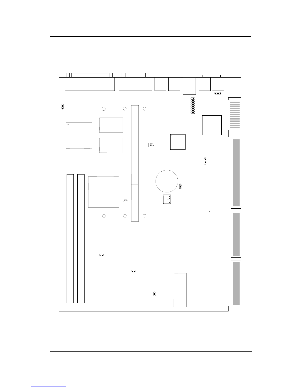
The MICRO NLX BX4 mainboard is a high-performance personal computer
mainboard based on Intel®
Pentium®
II processor. It combines ATI®
3D
RAGE128VR/RageXL/RageProAGPgraphicsaccelerator,YAMAHA®
YMF740C PCI enhanced audio, and Intel®
82559 10/100M Ethernet . The
Pentium®
II processor supports MMXTM (Multimedia Extension) technology.
The mainboard uses the highly integrated Intel®
82443BX chipset to support
the PCI/ISA and Green standards, and to provide the Host/AGP bridge. The
Intel®
82371EB chipset integrates all system control functions such as ACPI
(Advanced Configuration and Power Interface). The ACPI provides more
Energy Saving Features for the OSPM(OS Direct Power Management)
function. The Intel®
82371EB chipset also improves the IDE transfer rate by
supporting Ultra DMA/33 IDE that transfers data at the rate of 33MB/s.
The mainboard also supports the System Hardware Monitor Controller. This
function includes: CPU /power supply/chassis fan revolution detect, CPU/
system voltage monitor, system temperature monitor, and chassis intrusion
detect.

CHAPTER 1CHAPTER 1
CHAPTER 1CHAPTER 1
CHAPTER 1 INTRODUCTIONINTRODUCTION
INTRODUCTIONINTRODUCTION
INTRODUCTION
1.1 Mainboard Features
CPU
lSlot 1 for Pentium®
II/III or CeleronTM processor.
lSupports233MHz,266MHz,300MHz,333MHz,350MHz, 400MHz,
450MHz, and faster processor speeds.
lCore/Busratiosare x2,x2.5, x3,x3.5,x4,x4.5,x5,x5.5,x6andhigher.
SwitchingVoltageRegulator
lOn-board switching mode DC-DC Step Down Regulator.
lConforms to Intel®
VRM ver 8.2 specifications.
lOver-Voltage and Over-Current protection.
Chipset
lIntel®
82440BX AGP chipset.
ClockGenerator
l66.6MHz and 100MHz clocks are supported.
MainMemory
lSupports four memory banks using two 168-pin unbuffered DIMM.
lSupportsamaximum memorysizeof 256MB(8Mx8) or512MB(16M x4)
registered DIMM only.
lSupportsECC(1-bit Error Code Correct) function.
lSupports 3.3v SDRAM DIMM.
Video
lATI®
RAGE128VR/RageXL/RagePro
-Running on AGP BUS.
-Onboard8MBSGRAM (optional 4MB).
-3D Acceleration.
- AGP 2x mode (133MHz) support pipelined and sideband protocols.
1-2

CHAPTER 1CHAPTER 1
CHAPTER 1CHAPTER 1
CHAPTER 1 INTRODUCTIONINTRODUCTION
INTRODUCTIONINTRODUCTION
INTRODUCTION
1-3
SystemHardwareMonitor
lThis can be used with Intel®
LDCM to monitor system voltage, system
temperature & fan rotation speed.
lThis can also be used to monitor overall system status over the network.
lSystem temperature sensor: (TOP Tech)
- detect Pentium®
II processor’s temperature.
lSystem voltage monitor:
- monitorCPU core voltage, CPU interface voltage, 3.3v,+12v,+5v, VBAT
lFan speed monitor:
- monitor control chassis fan, power fan & CPU cooling fan speed.
PowerManagementFeatures
lDoze/Standby/Suspend mode.
lSystem management mode compliant.
lSupport APM 1.2.
lMeet ACPI spec.
lPC97/98compliant.
Audio
lYAMAHA®
YMF740C Audio Controller.
lSoundBlaster PRO Compatible.
lSupport Plug and Play:
- stereo 16-bit A/D
- stereo 16-bit D/A
lStereo enhancement support.
lAdvanced power management.
lMaximum32voice xG capitalwavetable.
lSynthesizer including GM compatible.

CHAPTER 1CHAPTER 1
CHAPTER 1CHAPTER 1
CHAPTER 1 INTRODUCTIONINTRODUCTION
INTRODUCTIONINTRODUCTION
INTRODUCTION
1-4
Network
lIntel®
8255910/100MEthernet.
lWFW baseline & NET PC specs compliant.
lAdvanced Power Management (ACPI support)
lMagic packet filtering to wake-up LAN.
lARP&FLEXIBLEframefiltering.
lSoftware drivers are backwards compatible.
lIPchecksumming in hardware.
Note: Requires an ATX power supply with 720mA 5VSB (5v Stand by).
RearMainboardConnectors
lPS/2 type keyboard/mouse connector.
lTwo COM port connectors.
lOnePrinter port with SPP/EPP/ECP function.
lRJ-45LANconnector.
lAudio connector
lVGAport
Dimension
lMICRONLXFormFactor: 20.3cm(L)x25.4cm(W)x4layersPCB.
OtherFeatures
lBulkEraseFlashROM.
lSupports DMI.
lSystem Wake-up by modem.
lSystem Wake-up by alarm.
lSoft-power off. (Windows®
95)
lPolyfuse function.
- this function works when the electric current is larger than 2A. It will
become an open circuit to protect your mainboard. Turn the power off for
1-3 secs for polyfuse to recover.
lLANwake-up.
lRestore AC power loss status.

CHAPTER 1CHAPTER 1
CHAPTER 1CHAPTER 1
CHAPTER 1 INTRODUCTIONINTRODUCTION
INTRODUCTIONINTRODUCTION
INTRODUCTION
1.2 Mainboard Layout
1-5
MS-6131 Micro NLX BX6 Mainboard
SLOT 1
DIMM 2
DIMM 1
mouse LAN
T: LPT
B: COM A
VGAPort
L-OUT
BATT
+
BIOS
FW82371EB
FW82443BX
Intel®
82559
10/100M
Ethernet
Yamaha
YMF740C
COMB
ATI®
Rage 128VR
Keyboard L-IN
(optional
MIC)
JP1
SW1
JBAT1
CPUFAN
JVGA1 JAUD1
JUSB
J5
JK1
J8
JK2
SDRAM
SDRAM

CHAPTER 2 HARDWARE INSTALLATION
2-1
Chapter 2
HARDWARE INSTALLATION
2.1 Central Processing Unit: CPU
The mainboard operates with Intel®
Pentium®
IIprocessorwith MMXTM
technology. The mainboard uses a CPU Slot called Slot 1 for easy CPU
installation and a DIP switch (SW1) to set the proper speed for the CPU.
The CPU should always have a Heat Sink and a cooling fan attached to
prevent overheating.

CHAPTER 2 HARDWARE INSTALLATION
2-2
2.1-1 CPU Installation Procedures
A. OEM Pentium®
II/III processor Installation Procedure
Required Things:
Pentium®
II/IIIprocessor- Processor.
*RetentionMechanism(RM)-PlasticGuidethatholdstheS.E.C.
Catridge/S.E.C.C.2 in the Slot 1 connector.
*RetentionMechanismAttachMount(RMAM)-Bolt/Bridgeassemblies
inserted up through the bottom of the
motherboard. RM secures to RMAM ( 2
RMAM required per RM ).
*Heat SinkSupport Base(HSSBASE) - Plastic support bar mounted to
the mainboard under the ATX heatsink.
(One leg is always bigger than the other one)
Processor
Lock
Retention
Mechanism
Pentium®
II/III
Processor
Heat Sink
W/Fan
Notch Hole
Heat Sink
Support Base Heat Sink
Support Pin
Heat Sink
Support
Top Bar
Different kinds of Pentium®
II/III processor that is currently used: the OEM
version, the Boxed version, and CeleronTM. OEM Pentium®
II/III Processor
has no Heat Sink, Fan and Heat Sink Support, the Boxed Pentium®
II/III
Processor is provided with Heat Sink w/ fan and Heat Sink Support, while
the CeleronTM processor is a plain processor card without cover or heatsink..

CHAPTER 2 HARDWARE INSTALLATION
2-3
*HeatSink SupportPin(HSSPIN) - Plastic pins inserted through the
HSSBASE to secure it to the mainboard (2
required per Assembly).
*Heat SinkSupportTop Bar (HSSTOP) - Plastic bar that clips onto the
HSSBASE through the fins on the ATX
heatsink.
**Heat Sink w/ fan - Heat Sink that can be attached to the Pentium®II/
III processorwithmetal clip.
Note:* Provided by MSI mainboard.
** Provided by Special request.
RM
HSSPIN
HSSTOP
HSSBASE
RMAM

CHAPTER 2 HARDWARE INSTALLATION
2-4
SLOT1
Retention
Mechanism
êê
Key
êê
Retention
Mechanism
Attach Mount
Notch
Key
Step 1: Insert the Retention Mechanism Attach Mount at the bottom
of the mainboard.
Step 2: Install the Retention Mechanism.
Look for the key on Slot 1, and match it with the Notch Key on the
Retention Mechanism for proper direction. Then, attach the
Retention Mechanism to the Retention Mechanism Attach Mount.
Use a Screwdriver to secure the Retention Mechanism.

CHAPTER 2 HARDWARE INSTALLATION
2-5
Step 3: Install the Heat Sink Support Base.
Look for the Two holes across Slot 1, and match it with the Two legs
of the Heat Sink Support Base for the proper direction. Take note
that one hole/leg is bigger than the other. The Four top pins of the
Heat Sink Support Base should also be oriented towards Slot 1.
Push the Heat Sink Support Base onto the mainboard, until you hear
a click sound. Check for a perfect fit.
Step 4: Install the Heat Sink Support Pin.
Push the Heat Sink Support Pins onto the two holes of the Heat Sink
Support Base. Check for a perfect fit. These pins are used to secure
the Heat Sink Support Base.
Heat Sink
Support Base
Heat Sink
Support Pin
Leg
pins

CHAPTER 2 HARDWARE INSTALLATION
2-6
Step 5: Install the Heat Sink with Fan to the Processor.
Push down the metal clips, so that they are in line with the back of
the Heat Sink. Be careful, so as not detach the metal clips from the
HeatSink.
In case the metal clips are detached from the Heat Sink, re-attach
them. Look for the arrow on the metal clip. This arrow should be
pointing down and aligned with the Heat Sink Support Base Holder.
Attach the Heat Sink to the processor.
- Look at the back of the Heat Sink and take note of the 2 secure
posts. Insert these 2 Secure posts to the 2 secure holes on the
back of the processor.
- Align the ears of the metal clips with the clip holders on the back of
the processor. Use a screw driver to push the metal clips onto the
clip holders. Check for a perfect fit.
Pentium®
II processor (Back)
â
Thearrow
shouldbe
pointing
down.
Metal Clips
Heat Sink w/ Fan
Metal Clips Ear
Metal Clips Ear
Secure
Posts
Heat Sink w/ Fan(Back)
HeatSink
BaseHolder
Secure
holes
Clip Holder
Clip Holder

CHAPTER 2 HARDWARE INSTALLATION
2-7
Step 6: Install the Processor.
Unlock the Processor by pushing in the Processor Locks.
Insert the Processor like inserting a PCI or an ISA card.
Step 7: Lock the Processor Locks.
Secure the CPU by pulling the Processor Locks out.
èç
çè

CHAPTER 2 HARDWARE INSTALLATION
2-8
Step 8: Install the Heat Sink Support Top Bar.
Push the Heat Sink Support Top Bar to the Heat Sink Support Base,
Until you hear a “click” sound. Check for a perfect fit.
The installation is now complete.
Heatsink
Support Top
Bar

CHAPTER 2 HARDWARE INSTALLATION
2-9
B. Boxed Pentium®
II/III processor Installation Procedures
The Boxed Pentium®
II/III processor has a built- in Fan and Heat Sink. It also
has a Heat Sink Support. So if you’re going to use the Boxed processor, all
you need is the Retention Mechanism.
SLOT1
Retention
Mechanism
êê
Key
êê
Retention
Mechanism
Attach Mount
Notch
Key
Step 1: Insert the Retention Mechanism Attach Mount at the bottom
of the mainboard.
Step 2: Install the Retention Mechanism.
Look for the key on Slot 1, and match it with the Notch Key on the
Retention Mechanism for proper direction. Then, attach the
Retention Mechanism to the Retention Mechanism Attach Mount.
Use a Screwdriver to secure the Retention Mechanism.

CHAPTER 2 HARDWARE INSTALLATION
2-10
Step 3: Install the Heat Sink Support Base.
Look for the 2 holes across Slot 1, and match it with the 2 Heat Sink
Support Base. Take note that one hole/base is bigger than the other.
Push the Heat Sink Support Base onto the mainboard, until you hear
a click sound. Check for a perfect fit.
Retention
Mechanism
Notch
Hole
HeatSink
Support Base

CHAPTER 2 HARDWARE INSTALLATION
2-11
PC-3743
HeatSink
Support Lock
Intel®
Boxed
PentiumTM II
Processor
Step 4: Install the Heat Sink Support.
Attach the 2 Heat Sink Supports to the sides of the Processor. These
Heat Sink Supports will fit in any direction, so be sure that the Heat
Sink Support Locks are oriented outwards for the proper direction.
HeatSink
Support

CHAPTER 2 HARDWARE INSTALLATION
2-12
PC-3744
Processor
Lock
Heatsink
Support
Lock
Step 5: Unlock the Processor Locks and Heat Sink Support Locks.
Push in the Processor Locks. Open the Heat Sink Support Locks.
Step 6: Insert the Processor like inserting a PCI or an ISA card.

CHAPTER 2 HARDWARE INSTALLATION
2-13
Step 7: Lock the Processor Locks and Heat Sink Support Locks
Secure the CPU by pushing out the Processor Locks. Close the Heat
Sink Support Locks.
The installation is now complete.

CHAPTER 2 HARDWARE INSTALLATION
2-14
SLOT1
Retention
Mechanism
êê
Key
êê
Retention
Mechanism
Attach Mount
Notch
Key
Step 1: Insert the Retention Mechanism Attach Mount at the bottom
of the mainboard.
Step 2: Install the Retention Mechanism.
Look for the key on Slot 1, and match it with the Notch Key on the
Retention Mechanism for proper direction. Then, attach the Reten-
tion Mechanism to the Retention Mechanism Attach Mount. Use a
Screwdriver to secure the Retention Mechanism.
C. OEM CeleronTM Processor and Pentium II (S.E.C.C. 2)
processor Installation Procedures

CHAPTER 2 HARDWARE INSTALLATION
2-15
Step 3: Install the MSI Heat Sink (optional) to the Processor.
Push down the plastic clips, so that they are in line with the hole on
the processor. Check for perfect fit.
Step 4: Install the Processor.
Insert the Processor like inserting a PCI or an ISA card.
Step 5: Lock the Processor.
Lock the processor by putting the MSI Retention Cap provided. The
MSI Retention Cap will only fit in one direction. The MSI Retention
Cap is only used with Intel®
CeleronTM processor and Intel®
Penitum®
II processor (S.E.C.C. 2).
ê
Heat Sink
CeleronTM
processor
ê
plastic Clip
The instruction procedure may
vary depending on the Heat Sink
that you’re using.
ê
MSI Retention Cap
Notch
Hole Notch
Hole
ê
Table of contents
Other MSI Motherboard manuals

MSI
MSI MS-6318 User manual

MSI
MSI B75IA-E33 Series User manual

MSI
MSI B85M-P33 V3 Series User manual

MSI
MSI MAG X670E TOMAHAWK WIFI User manual

MSI
MSI Z77A-G43 GAMING User manual

MSI
MSI MEG Z690 GODLIKE User manual

MSI
MSI 865PE Neo3-F User manual

MSI
MSI P45 NEO3-FR - Motherboard - ATX User manual

MSI
MSI 870A Fuzion Power Edition series User manual

MSI
MSI B350M PRO-VDH User manual