MSI E7210 Master-FARM User manual

i
Version1.0
G52-S9149X1
E7210 Master-FARM
MS-9149 (v1.X)ATXServerBoard

ii iii
ManualRev:1.0
ReleaseDate:October2003
FCC-ARadio Frequency Interference Statement
Thisequipmenthasbeentestedand foundtocomplywiththelimitsforaclass
Adigitaldevice,pursuanttopart15oftheFCCrules.Theselimitsaredesigned
toprovidereasonableprotection againstharmfulinterference whentheequip-
mentisoperatedinacommercialenvironment.Thisequipmentgenerates,uses
and canradiateradiofrequencyenergyand,ifnotinstalledandusedinaccor-
dance withtheinstruction manual,maycauseharmfulinterference toradio
communications.Operation ofthisequipmentinaresidentialarea islikelyto
causeharmfulinterference,inwhichcasetheuserwillberequiredtocorrect
theinterference athisownexpense.
Notice 1
Thechangesormodificationsnotexpresslyapprovedby thepartyrespon-
sibleforcompliancecouldvoidtheuser’sauthoritytooperatetheequipment.
Notice 2
ShieldedinterfacecablesandA.C.powercord,ifany,mustbeusedinorderto
complywiththeemission limits.
VOIRLANOTICED’INSTALLATIONAVANTDERACCORDERAU
RESEAU.
CopyrightNotice
ThematerialinthisdocumentistheintellectualpropertyofMICRO-STAR
INTERNATIONAL.Wetakeeverycareinthepreparation ofthisdocument,
butno guarantee isgivenastothecorrectness ofitscontents.Ourproducts
areundercontinualimprovementand wereservetherighttomakechanges
withoutnotice.
Trademarks
Alltrademarksarethepropertiesoftheirrespectiveowners.
Intel®and Pentium®areregisteredtrademarksofIntelCorporation.
PS/2and OS®/2areregisteredtrademarksofInternationalBusiness Machines
Corporation.
Windows®95/98/2000/NT/XPareregisteredtrademarksofMicrosoft
Corporation.
Netware®isaregisteredtrademarkofNovell,Inc.
Award®isaregisteredtrademarkofPhoenixTechnologiesLtd.
AMI®isaregisteredtrademarkofAmericanMegatrendsInc.
RevisionHistory
RevisionRevisionHistoryDate
V1.0FirstreleaseforPCB1.X October2003
TechnicalSupport
If aproblemariseswithyoursystemand no solution canbeobtainedfromthe
user’smanual,pleasecontactyourplace ofpurchaseorlocaldistributor.
Alternatively,pleasetrythefollowing helpresourcesforfurtherguidance.
Visit theMSIwebsiteforFAQ,technicalguide,BIOSupdates,driver
updates,and otherinformation:http://www.msi.com.tw/
Contactourtechnicalstaff at:support@msi.com.tw
Micro-StarInternationalMS-9149
Testedtocomply
withFCC Standard
ForHomeorOffice Use

iv v
CONTENTS
FCC-ARadioFrequencyInterference Statement............................................... ii
CopyrightNotice .................................................................................................... iii
Trademarks.............................................................................................................. iii
Revision History..................................................................................................... iii
TechnicalSupport................................................................................................... iii
SafetyInstructions.................................................................................................iv
Chapter 1.GettingStarted................................................................................ 1-1
MainboardSpecifications............................................................................1-2
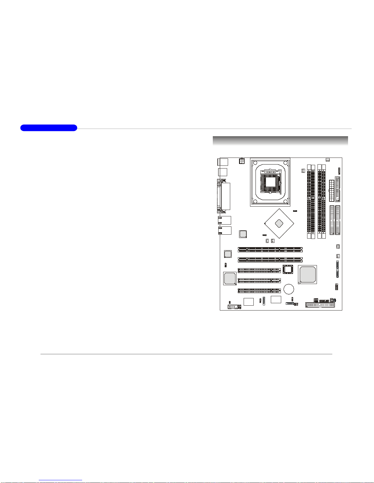
MainboardLayout........................................................................................1-5
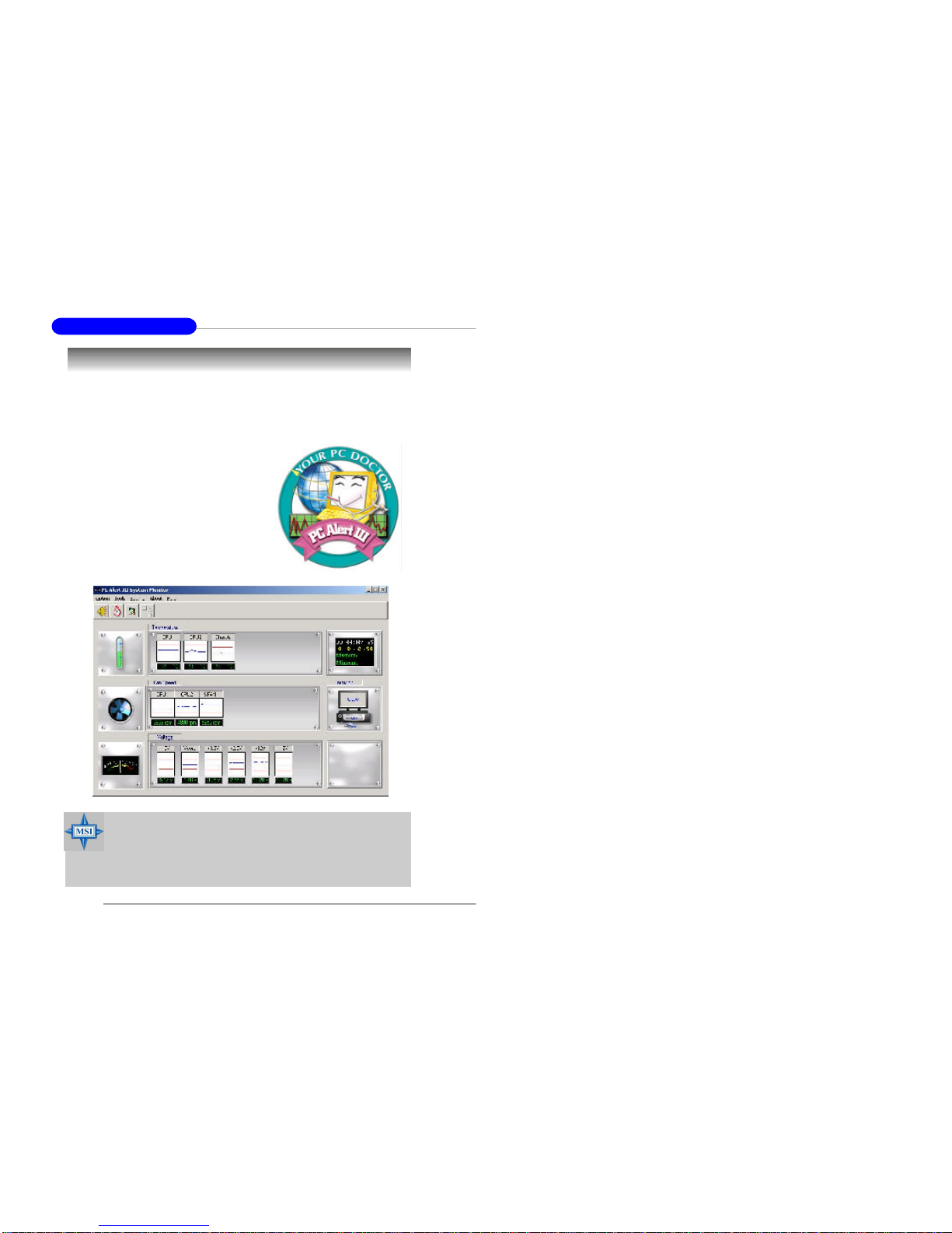
MSISpecialFeatures....................................................................................1-6
PCAlert™III ..........................................................................................1-6
Chapter 2.Hardware Setup............................................................................... 2-1
QuickComponentsGuide............................................................................2-2
CentralProcessing Unit:CPU......................................................................2-3
CPUCoreSpeedDerivation Procedure..............................................2-3
CPUInstallation ProceduresforSocket478......................................2-4
Installing theCPUFan..........................................................................2-5
Memory...........................................................................................................2-7
MemorySpeed/CPUFSBSupportMatrix..........................................2-7
DIMM ModuleCombination ...............................................................2-7
Installing DDRModules.......................................................................2-8
PowerSupply.................................................................................................2-9
ATX20-pinPowerConnector:JPWR2...............................................2-9
ATX12VPowerConnector:JPWR1...................................................2-9
BackPanel....................................................................................................2-10
Connectors,Jumpers&Slots....................................................................2-11
Floppy DiskDriveConnector:JFDD1..............................................2-11
HardDiskConnectors:IDE1/2...........................................................2-11
SATAConnectorsSupportedby ICH-HR:SATA1&SATA2......2-12
1.Alwaysreadthesafetyinstructionscarefully.
2.KeepthisUser’sManualforfuturereference.
3.Keepthisequipmentawayfromhumidity.
4.Laythisequipmenton areliableflatsurface beforesetting it up.
5.Theopeningson theenclosureareforairconvection hence protectsthe
equipmentfromoverheating.DO NOTCOVERTHEOPENINGS.
6.Makesurethevoltageofthepowersource andadjustproperly110/220V
beforeconnecting theequipmenttothepowerinlet.
7.Place thepowercordsuchawaythatpeoplecannotstepon it.Donot
place anything overthepowercord.
8.AlwaysUnplugthePowerCordbeforeinsertinganyadd-oncardormodule.
9.Allcautionsand warningson theequipmentshouldbenoted.
10.Neverpourany liquidintotheopening thatcoulddamageorcauseelectri-
calshock.
11.If any ofthefollowing situationsarises,gettheequipmentcheckedby a
service personnel:
lThepowercordorplug isdamaged.
lLiquidhaspenetratedintotheequipment.
lTheequipmenthasbeenexposedtomoisture.
lTheequipmenthasnotworkwelloryou cannotgetitworkaccording
toUser’sManual.
lTheequipmenthasdroppedand damaged.
lTheequipmenthasobvioussign ofbreakage.
12.DO NOTLEAVETHISEQUIPMENTINA N ENVIRONMENT
UNCONDITIONED,STORAGETEMPERATUREABOVE600C(1400F),IT
MAYDAMAGETHEEQUIPMENT.
Safety Instructions
CAUTION:Dangerofexplosion ifbatteryisincorrectlyreplaced.
Replace onlywiththesameorequivalenttyperecommendedby the
manufacturer.
警告使用者:
這是甲類的資訊產品,在居住的環境中使用時,可能會造成無線電干
擾,在這種情況下,使用者會被要求採取某些適當的對策。

vivii
AdvancedBIOSFeatures..........................................................................3-10
AdvancedChipsetFeatures......................................................................3-15
IntegratedPeripherals.................................................................................3-17
PowerManagementSetup .........................................................................3-22
PnP/PCIConfigurations.............................................................................3-24
PCHealthStatus..........................................................................................3-26
Frequency/VoltageControl........................................................................3-27
LoadFail-Safe/OptimizedDefaults...........................................................3-28
SetSupervisor/UserPassword..................................................................3-29
HardDiskRAIDConnectorsSupportedbyPromisePDC20378:IDE3,
SATA3&SATA4(Optional).............................................................2-12
FanPowerConnectors:CPUFAN1,SYSFAN1/2/3/4/5..................2-13
LCDPanelConnector:JLCD1(Optional).........................................2-14
I2CBusConnector:JIPMB1..............................................................2-14
82547GILAN ActiveLEDConnector:JACT1(Optional)............2-14
82541GILAN ActiveLEDConnector:JACT2(Optional)............2-14
FrontPanelConnector:JFP1.............................................................2-15
FrontUSBConnector:JUSB2............................................................2-15
ChassisIntrusion SwitchConnector:JCI1......................................2-16
ISABridgeControlConnector:JISA1.............................................2-16
Enable/DisablePROMISESATAHeader:J2...................................2-16
PCI-XDevicesHeader:J4..................................................................2-16
PCI-XBusSpeedHeader:J5..............................................................2-17
FWHWriteProtectConnector:J9....................................................2-17
IDHeaderforBIOSVersion:J10&J11 ............................................2-17
Enable/DisableVGA Jumper:J8........................................................2-17
Enable/Disable82541EILAN Jumper:J1........................................2-18
ClearCMOSJumper:JBAT1..............................................................2-18
SystemConfigureJumper:J3.............................................................2-19
PCI(PeripheralComponentInterconnect)Slots.............................2-19
PCIInterruptRequestRouting..........................................................2-20
Chapter 3.BIOSSetup ...................................................................................... 3-1
Entering Setup ...............................................................................................3-2
ControlKeys..........................................................................................3-2
Getting Help...........................................................................................3-3
TheMainMenu ............................................................................................3-4
StandardCMOSFeatures............................................................................3-6
IPMIV1.5BIOSFeatures.............................................................................3-8

1-1
Getting Started
Chapter1.Getting
Started
GettingStarted
Thankyou forchoosing theE7210 Master-FARM(MS-
9149v1.X)ATXserverboard.TheE7210 Master-FARMisa
superiorcomputermainboardbasedon Intel®Canterwood-ES
&Hance Rapidschipsetsforoptimalsystemefficiency.Designed
tofit theadvancedIntel®P4(Northwood/Prescott)processor,
thismainboardprovidesacost-effectiveandprofessionalsolu-
tion forhigh-end workstation and servermarkets.

1-3
Getting Started
1-2
MS-9149 ATXServerBoard
OnboardS-ATA
†4xS-ATA,2fromsouthbridge,2fromPromisecontroller(optional:Promise
20378RAIDcontroller)
†RAID0,1support
OnboardI/O
†On-BoardPeripheralsinclude:
-1xPS/2Keyboard/MousePort
-1xfloppy port
-2xserialports
-1xparallelport
-2xUSB2.0ports(rear)
-2xUSB2.0ports(front)
-2xRJ-45
BIOS
†PCI2.2compliant,VPDand DMI
†PnP1.0A,SMBIOS2.3,ACPI2.0
†SupportsPXEbootprotocol
†APM1.2
†WOL
†WOR
†USBkeyboardand mouse
†PC2001systemdesign compliant
†BIOSFlashWriteProtect
†BBS
†EventLog
†USBLegacySupportKB&Mouse
†ChassisIntrusion
†ConsoleRedirection
†ACRecovery(backtooriginalstatus)
†RTCalarmand wakeup
†BootBlock
†RemoteDiag.
MainboardSpecifications
CPU
†SupportsIntel®P4(Northwood/Prescott)processors
†Supports533/800MHzFSB
†Meetsthermalrequirements
†Onboardvoltageregulatormodule
Chipset
†Intel®Canterwood-ES+Hance Rapids
†LPCSuperI/Ocontrollerwithfloppy writeprotectfunction
†4Mbit FlashEEPROM
MainMemory
†Supports4GBECCmemory
†4DDRDIMM sockets
†SupportsPC3200ECC,unbuffered
OnboardVGA
†ATIRageXLwith8MBSDRAM
OnboardLAN
†OnboarddualIntelGigabit LAN
†Intel82547GIGigabit LAN
†Intel82541GIGigabit LAN
†ProgrammedEthernetMACaddress and EEPROM
MSIServer Management: (Optional)
†mBMCand MSIiConsolesupportIPMI1.5
Slots
†3xPCI32bit/33MHzslots
†2xPCI64bit/66MHzslots
OnboardIDE
†2xIDEconnectortosupportATA100/66/33
†1xIDERAIDconnectorfor0,1and 0+1support(optional:Promise20378
RAIDcontroller)

1-5
Getting Started
1-4
MS-9149 ATXServerBoard
MainboardLayout
E7210 Master-FARM(MS-9149 v1.X)ATXServerBoard
D
I
M
M
1
D
I
M
M
3
D
I
M
M
2
D
I
M
M
4
Top : mouse
Bottom: keyboard
USB ports
JPWR1
COM2
Intel
82541GI
Intel
82547GI
BATT
+
BIOS
NS
PC87366
Promise
PDC20378
Intel
Hance Rapids
Intel
Canterwood-ES
Chipsets
IDE1
IDE 3
IDE2
J
F
D
D
1
PCI Slot 1
PCIX1
PCIX2
PCI Slot 2
PCI Slot 3
CPUFAN1
SYSFAN2 SYSFAN3
SYSFAN1
SYSFAN4
SYSFAN5
JFP1
JACT1
JACT2
JISA1
J10
J8
J11
J1
JBAT1
J9
J3
J4
J5
JLCD1
JCI1
JPWR2
JIPMB1
SATA2
SATA3 SATA4
JUSB2
SATA1
Top : LPT
Bottom:
COM A
VGAport
ATI
RageXL
RJ45 LAN jack
RJ45 LAN jack
J2
Power ManagementFeatures
†RTCalarmand wakeup
†Wakeup on LAN (WOL)
†Wakeup on serialring
†Wakeup on Keyboard/MousefromS1
†Wakeup on USBfromS1
†Wakeup on PCI
†SupportsACPIS1/S4/S5functions
Regulatory
†FCCClass B
†EMC
†CE
BoardSize
†ATXcompatibleformfactorwith9mounting holes

1-6
MS-9149 ATXServerBoard
PCAlert™III
ThePCAlertTMIII isautilityyou canfind intheCD-ROMdisk.The
utilityisjustlikeyourPCdoctorthatcandetectthefollowing PChardware
statusduring realtimeoperation:
ömonitorCPU&systemtemperatures
ömonitorfanspeed(s)
ömonitorsystemvoltage
ömonitorchassisintrusion
If oneoftheitemsaboveisabnormal,
theprogrammainscreenwillbeimmediately
shownon thescreen,withtheabnormalitem
highlightedinred.Thiswill continuetobe
shownuntiluserdisablesthewarning.
MSISpecialFeatures
MSIRemindsYou...
1.Itemsshownon PCAlert™III varydepending on yoursystem
status.
2.ThisfeatureisonlyavailableforMS-9149 mainboardwithout
mBMCchipset.

2-1
HardwareSetup
Chapter2.Hardware
Setup
HardwareSetup
Thischapterprovidesyouwiththeinformation abouthard-
waresetup procedures.Whiledoing theinstallation,becareful
inholding thecomponentsand followtheinstallation
procedures.Forsomecomponents,ifyou installinthewrong
orientation,thecomponentswill notworkproperly.
Useagroundedwriststrapbeforehandling computer
components.Staticelectricitymaydamagethecomponents.

2-3
HardwareSetup
2-2
MS-9149 ATXServerBoard
QuickComponentsGuideCentralProcessingUnit: CPU
CPUCore SpeedDerivationProcedure
IfCPUClock=100MHz
Core/Busratio=17
thenCPUcorespeed=HostClockxCore/Busratio
=100MHzx17
=1.7GHz
ThemainboardsupportsIntel®Pentium®4Northwood /Prescott proces-
sorinthe478pinpackage.ThemainboardusesaCPUsocketcalledPGA478
foreasyCPUinstallation.Whenyou areinstalling theCPU,makesure the
CPUhasaheatsink andacoolingfanattachedonthetoptopreventoverheating.
If you do notfind theheatsinkand cooling fan,contactyourdealertopur-
chaseand installthembeforeturning on thecomputer.
MSIRemindsYou...
Overheating
Overheating will seriouslydamagetheCPUand system,always
make surethecooling fan canworkproperlytoprotecttheCPU
fromoverheating.
ReplacingtheCPU
Whilereplacing theCPU,alwaysturnofftheATXpowersupply
orunplug thepowersupply’spowercordfromgroundedoutlet
firsttoensurethesafetyofCPU.

2-5
HardwareSetup
2-4
MS-9149 ATXServerBoard
Installing theCPUFan
Asprocessortechnology pushestofasterspeedsand higher
performance,thermalmanagementbecomesincreasinglyimportant.Todissi-
pateheat,you needtoattachtheCPUcooling fanand heatsinkon top ofthe
CPU.FollowtheinstructionsbelowtoinstalltheHeatsink/Fan:
2.Position the heatsinkontothe reten-
tion mechanism.
1.Locatethe CPUand itsretention
mechanismon the motherboard.
3.Mountthe fan on top ofthe heatsink.
Press downthe fan until itsfourclips
getwedgedintheholesofthe reten-
tion mechanism.
4.Press thetwoleversdowntofasten
the fan.Eachlevercan be pressed
downinonlyONEdirection.
retention mechanism
levers
CPUInstallationProceduresforSocket478
1.Pleaseturnoffthepowerand
unplugthepowercordbefore
installing theCPU.
2.Pulltheleversidewaysaway
fromthesocket.Makesure
toraisetheleverup toa90-
degree angle.
3.Lookforthegoldarrow.The
goldarrowshouldpointto-
wardstheleverpivot.The
CPUcanonlyfit inthecorrect
orientation.
4.If theCPUiscorrectly
installed,thepinsshouldbe
completelyembeddedintothe
socketand cannotbeseen.
Pleasenotethatany violation
ofthecorrectinstallation pro-
ceduresmaycausepermanent
damagestoyourmainboard.
5.PresstheCPUdownfirmlyinto
thesocketandclosethelever.
AstheCPUislikelytomove
whiletheleverisbeingclosed,
alwaysclosetheleverwith
yourfingerspressing tightly
ontop oftheCPUtomakesure
theCPUisproperlyand com-
pletelyembeddedintothe
socket.
Open Lever
90 degree
Sliding
Plate
Close
Lever
Press down
the CPU
Gold arrow
Gold arrow
Gold arrow
Correct CPU placement
Incorrect CPU placement
X
O

2-7
HardwareSetup
2-6
MS-9149 ATXServerBoard
Memory
5.Connectthefan powercablefromthemounted fan tothe 3-pinfanpowerconnec-
toron the board.
fan powercable
NOTES
Themainboardprovidesfour184-pinECCnon-registeredDDR266/
DDR333/DDR400SDRAMwiththemaximummemorysize upto4GB.Tooper-
ateproperly,installatleastonememorymoduleon theslot.Toachievethe
optimalefficiencyofdualchannel,install memorymoduleson ChannelA
(DIMM 1&2)and ChannelB(DIMM3&4).Makesurethatyou install
memorymodulesofthesametypeand densityon thesamechannel.
DIMM1~DIMM4
(fromleft toright)
Memory Speed/CPUFSBSupportMatrix
CPUFSB
MemoryDDR266 DDR333 DDR400
YesYesYes
533MHz
800MHzYesYesYes
Thememorymodulescanbeinstalledinthefollowing combination:
DIMM ModuleCombination

2-9
HardwareSetup
2-8
MS-9149 ATXServerBoard
Power Supply
ThemainboardsupportsSSIpowersupplyforthepowersystem.Be-
foreinserting thepowersupplyconnector,alwaysmakesurethatallcompo-
nentsareinstalledproperlytoensurethatno damagewillbecaused.
ATX20-PinPower Connector:JPWR2
Thisconnectorallowsyou toconnecttoanATXpowersupply.To
connecttotheATXpowersupply,makesuretheplug ofthepowersupplyis
insertedintheproperorientation and thepinsarealigned.Thenpushdown
thepowersupplyfirmlyintotheconnector.
ATX12VPowerConnector:JPWR1
This12VpowerconnectorisusedtoprovidepowertotheCPU.
Installing DDR Modules
1.TheDDRDIMM hasonlyonenotchon thecenterofmodule.Themodule
willonlyfit intherightorientation.
2.InserttheDIMM memorymoduleverticallyintotheDIMM slot.Then
pushit inuntilthegoldenfingeronthememorymoduleisdeeplyinserted
inthesocket.
3.TheplasticclipateachsideoftheDIMM slotwillautomaticallyclose.
VoltNotch
PINSIGNAL
1GND
2GND
3 12V
4 12V
JPWR1PinDefinition PINSIGNAL
11 3.3V
12 -12V
13 GND
14 PS_ON
15 GND
16 GND
17 GND
18 -5V
19 5V
20 5V
PINSIGNAL
1 3.3V
2 3.3V
3GND
4 5V
5GND
6 5V
7GND
8PW_OK
9 5V_SB
10 12V
JPWR2PinDefinition
JPWR2
JPWR1
DIMM1DIMM2DIMM3DIMM4TotalMemory
128MB~1GB128MB~1GB
128MB~1GB128MB~1GB
128MB~1GB128MB~1GB
128MB~1GB128MB~1GB
128MB~1GB128MB~1GB256MB~2GB
128MB~1GB128MB~1GB128MB~1GB384MB~3GB
128MB~1GB128MB~1GB128MB~1GB128MB~1GB512MB~4GB
MSIRemindsYou...
You can barelysee thegoldenfingerifthemoduleisproperly
insertedinthesocket.

2-11
HardwareSetup
2-10
MS-9149 ATXServerBoard
Connectors,Jumpers&Slots
MSIRemindsYou...
Ifyou install twoharddiskson cable,you mustconfigurethe
second drive toSlave modebysetting itsjumper.Refertothe
harddiskdocumentation suppliedbyharddiskvendors for
jumpersettinginstructions.
HardDiskConnectors:IDE1/2
Themainboardhasa32-bit EnhancedPCIIDEand UltraDMA33/66/
100controllerthatprovidesPIOmode0~4,BusMaster,and UltraDMA33/
66/100 function.You canconnectup tofourharddiskdrives,CD-ROM,
120MBFloppy (reservedforfutureBIOS)and otherdevices.Theseconnec-
torssupporttheprovidedIDEharddiskcable.
IDE1(PrimaryIDEConnector)
ThefirstharddriveshouldalwaysbeconnectedtoIDE1.IDE1can
connectaMasterand aSlavedrive.You mustconfiguresecond hard
drivetoSlavemodeby setting thejumperaccordingly.
IDE2(SecondaryIDEConnector)
IDE2canalsoconnectaMasterand aSlavedrive.
BackPanel
Mouse
Keyboard
USB
Parallel
COMALAN1VGA
SerialPorts
KB/Mouse Connector
VGAPort
USBPorts
PINSIGNAL
1VCC
LAN2
RJ-45LANJack
81
GigabitLAN PinDefinition
1D0PDifferentialPair0+
2D0N DifferentialPair0-
3D1PDifferentialPair1+
4D2PDifferentialPair2+
5D2N DifferentialPair2-
6D1N DifferentialPair1-
7D3PDifferentialPair3+
8D3N DifferentialPair3-
PINSIGNAL
COM2
IDE1IDE2
Floppy DiskDriveConnector:JFDD1
Themainboardprovidesastandardfloppy diskdriveconnectorthat
supports360K,720K,1.2M,1.44Mand 2.88Mfloppy disktypes.
JFDD1
VGAConnector
(DB15-pin)

2-13
HardwareSetup
2-12
MS-9149 ATXServerBoard
SATAConnectorsSupportedby ICH-HR:SATA1 &SATA2
HardDiskRAIDConnectorsSupportedbyPromisePDC20378:
IDE3, SATA3 &SATA4 (Optional)
ThePromise20378 chipsetsupportsoneIDERAIDconnector(IDE3)
and twoSATAconnectors(SATA3&SATA4).TheICH-HRchipsetsupports
twoserialIDEconnectors(SATA1&SATA2).
IDE3isa32-bit EnhancedPCIIDEand UltraDMA66/100/133controller
thatprovidesPIOmode0~5,BusMaster,and UltraDMA66/100/133function.
You canconnectup to2harddiskdrives,CD-ROM,120MBFloppy (reserved
forfutureBIOS)and otherdevices.
SATAconnectorsaredualhigh-speedSerialATAinterface ports.Each
supports1stgeneration serialATAdataratesof150MB/s.Allconnectorsare
fullycompliantwithSerialATA1.0specifications.EachSerialATAconnector
canconnectto1harddiskdevice.PleaserefertoSerialATA/SerialATARAID
manualfordetailedsoftwareinstallation procedures.
SATA4
PINSIGNALPINSIGNAL
1GND 2TXP
3TXN4GND
5RXN6RXP
7GND
SATAPinDefinitions
SATA3SATA1/2
FanPowerConnectors:CPUFAN1, SYSFAN1/2/3/4/5
TheCPUFAN1(processorfan)and SYSFAN1/2/3/4/5(systemfans)sup-
portsystemcoolingfanwith+12V.Itsupportsthree-pinheadconnector.When
connecting thewiretotheconnectors,alwaystakenotethattheredwireisthe
positiveand shouldbeconnectedtothe+12V,theblackwireisGround and
shouldbeconnectedtoGND.If themainboardhasaSystemHardwareMoni-
torchipseton-board,you mustuseaspeciallydesignedfanwithspeedsensor
totakeadvantageoftheCPUfancontrol.
MSIRemindsYou...
Pleasedo notfoldtheSerialATAcableinto90-degree angle.
Otherwise,theloss ofdatamayoccurduring transmission.
ConnecttoSATA1/2/3/4
OptionalSerialATAcable
MSIRemindsYou...
Alwaysconsult thevendorsforproperCPUcooling fan.
CPUFAN1SYSFAN1SYSFAN4
SYSFAN3SYSFAN2SYSFAN5

2-15
HardwareSetup
2-14
MS-9149 ATXServerBoard
FrontPanelConnector:JFP1
Themainboardprovidesonefrontpanelconnectorforelectrical
connection tothefrontpanelswitchesand LEDs.JFP1iscompliantwithIntel®
FrontPanelI/OConnectivityDesign Guide.
FrontUSBConnector:JUSB2
ThemainboardprovidesoneUSB2.0pinheaderJUSB2thatiscompliant
withIntel®I/OConnectivityDesign Guide.USB2.0technologyincreasesdata
transferrateup toamaximumthroughputof480Mbps,whichis40timesfaster
thanUSB1.1,and isidealforconnecting high-speedUSBinterface peripherals
suchasUSBHDD,digitalcameras,MP3players,printers,modemsandthe
like.
JFP1
PINSIGNALDESCRIPTION
1HD_LED_PHarddiskLEDpull-up
2FPPWR/SLPMSGLEDpull-up
3HD_LED_N HarddiskactiveLED
4FPPWR/SLPMSGLEDpull-up
5RST_SW_N ResetSwitchlowreferencepull-downtoGND
6PWR_SW_P PowerSwitchhigh referencepull-up
7RST_SW_PResetSwitchhigh referencepull-up
8PWR_SW_NPowerSwitchlowreferencepull-downtoGND
9RSVD_DNU Reserved.Donotuse.
JFP1PinDefinition
PINSIGNALPINSIGNAL
1VCC 2VCC
3USB0-4USB1-
5USB0+6USB1+
7GND 8GND
9Key10 NC
JUSB2PinDefinition
JUSB2
LCD PanelConnector:JLCD1 (Optional)
Theconnectorisadditionallyprovidedforconnection toaLCDpanel,
whichshowsinformationon thepanelforyou toidentifythecurrentstatusor
modeoftheconnectedsystem.
PINSIGNAL
1SOUT
2SIN
3NC
4GND1
5GND0
6VCC
JLCD1
I2CBusConnector:JIPMB1 (Optional)
ThemainboardprovidesoneI2C(alsoknownasI2C)Busconnectorfor
userstoconnecttoSystemManagementBus(SMBus)interface.
PINSIGNAL
1SMBCLK
2SMBDATA
3SMBALERT#
4GND
5VCC3
JIPMB1PinDefinition
JIPMB1
82547 GILAN ActiveLEDConnector:JACT1 (Optional)
82541 GILAN ActiveLEDConnector:JACT2 (Optional)
TheLAN LEDconnectorsareusedtoconnecttoLAN LEDs,which
showtheactivityoftheLAN.JACT1isforLAN1jackand theJACT2isfor
LAN2jack.BothLAN1&LAN2jacksarelocatedon thebackpanel.
JACT1JACT2

2-17
HardwareSetup
2-16
MS-9149 ATXServerBoard
ChassisIntrusionSwitchConnector:JCI1
Thisconnectorisconnectedtoa2-pinchassisswitch.If thechassisis
opened,theswitchwillbeshort.Thesystemwillrecordthisstatusand show
awarning messageon thescreen.Toclearthewarning,you mustenterthe
BIOSutilityand cleartherecord.
Enable/DisablePROMISESATAHeader:J2
J2 DisableSATAIDSEL
EnableSATAIDSEL
(default)
ISABridgeControlConnector:JISA1 (Optional)
JISA1
FWHWriteProtectConnector:J9
DisableFWHWrite
Protect(default)
EnableFWHWriteProtect
J9
PCI-XDevicesHeader:J4
PCI-XBusSpeedHeader:J5
NotPCI-XDevice
PCI-XDevice
(default)
J4
PCI-XBusSpeedis
33MHz
PCI-XBusSpeedis
66MHz(default)
J5
IDHeaderforBIOSVersion:J10 &J11
J10 J11
JCI1
Enable/DisableVGAJumper:J8
ThisjumperisusedtoenableordisableVGA IDSEL.
J8

2-19
HardwareSetup
2-18
MS-9149 ATXServerBoard
SystemConfigure Jumper:J3
TheJ3jumperdetermineswhichmodethesystemwill enterwhilepow-
eredon.During NormalMode,thesystemwillentertheassignedOSasusual.
During ConfigureMode,thesystemwilldirectlyenterBIOSsetuputility.This
enablesyou tomodifytheBIOSconfigurations.During RecoveryMode,you
havetoinsertcertainbootdiskintothefloppy drivebeforepowering on the
system.Afterpoweredon,thesystemwillreadthebootdiskand enterDOS.
Thisenablesyou toupdatetheBIOSwithaFlashutilityifnecessary.
NormalModeConfigureModeRecoveryMode
J3
MSIRemindsYou...
You canclearCMOSbyshorting 2-3pinwhilethesystemisoff.
Thenreturnto1-2pinposition.AvoidclearingtheCMOSwhile
thesystemison;it willdamagethemainboard.
ClearCMOSJumper:JBAT1
ThereisaCMOSRAMon boardthathasapowersupplyfromexternal
batterytokeepthedataofsystemconfiguration.WiththeCMOSRAM,the
systemcanautomaticallybootOSeverytimeit isturnedon.If you wantto
clearthesystemconfiguration,usetheJBAT1(ClearCMOSJumper)toclear
data.Followtheinstructionsbelowtoclearthedata:
JBAT1ClearData
KeepData
Enable/Disable82541 GILAN Jumper:J1
TheLAN controllerintegratedon themotherboardvariesdepending on
themodelyou havepurchased.Thedefault factorysettingsareproperly
configuredforoptimalsystemperformanceand thusshouldbeleftunchanged.
J1 DisableLAN IDSEL
EnableLAN IDSEL
(default)
PCISlots
FivePCIslotsallowyou toinserttheexpansion cardstomeetyour
needs.Whenaddingorremovingexpansion cards,makesurethatyouunplug
thepowersupplyfirst.Meanwhile,readthedocumentationfortheexpansion
cardtomakeany necessaryhardwareorsoftwaresettingsfortheexpansion
card,suchasjumpers,switchesorBIOSconfiguration.Three PCIslotsare
conventional32-bit PCIbusslotsand theothertwoare64-bit PCIbus(also
calledPCIX)slots.
32-bitPCIbus:Thebushas32datalinesand runsat33MHz.
64-bitPCIbus:Thebushas64datalinesand runsat33,66MHz.With
twice datalinesand muchfasterPCIclock,the64-bitPCIbusincreases
thethroughputand overallsystemperformance.
ThemotherboardprovidestwoPCI-X64bit/66MHzand three PCI32bit/
33MHzslots.

2-20
MS-9149 ATXServerBoard
PCIInterruptRequestRouting
TheIRQ,abbreviation ofinterruptrequestlineand pronouncedI-R-Q,
arehardwarelinesoverwhichdevicescansend interruptsignalstothe
microprocessor.ThePCIIRQpinsaretypicallyconnectedtothePCIbusINT
A#~INTD#pinsasfollows:
PrimaryIDEInterrupt:IRQ14(forICH-HR)
SecondaryIDEInterrupt:IRQ15(forICH-HR)
PCI-32 IRQRouting(forICH-HR)
PCIDeviceINTAINTBINTCINTD
PCI32 Slot1PIRQ#A PIRQ#B PIRQ#CPIRQ#D
PCI32 Slot2PIRQ#B PIRQ#CPIRQ#DPIRQ#A
PCI32 Slot3PIRQ#CPIRQ#DPIRQ#A PIRQ#B
VGA PIRQ#G
82541 GILANPIRQ#H
PDC20378 PIRQ#E
PCIX-64 IRQRouting(forICH-HR)
CSAInterface IRQrouting(forCanterwood-ES)
PCIDeviceINTAINTBINTCINTD
82547 GILANPIRQ#F
PCIDeviceINTAINTBINTCINTD
PCIX-64 Slot1PX_IRQ#0 PX_IRQ#1 PX_IRQ#2 PX_IRQ#3
PCIX-64 Slot2PX_IRQ#1 PX_IRQ#2 PX_IRQ#3 PX_IRQ#0

3-1
BIOSSetup
Thischapterprovidesinformationon theBIOSSetup pro-
gramand allowsyou toconfigurethesystemforoptimumuse.
You mayneedtorun theSetup programwhen:
²Anerrormessageappearson thescreenduring thesystem
booting up,and requestsyou torun SETUP.
²You wanttochangethedefault settingsforcustomized
features.
BIOSSetup
This manual suits for next models
1
Table of contents
Other MSI Server Board manuals

MSI
MSI 3200 Master Series User manual

MSI
MSI K9ND Speedster2 Series User manual

MSI
MSI MS-S0081 User manual

MSI
MSI 5000V Master2 Series User manual

MSI
MSI E7520 Master S2M User manual

MSI
MSI MS-96D7 User manual

MSI
MSI 5500 Master Series User manual

MSI
MSI MS-S0131 User manual

MSI
MSI K9SD Master User manual

MSI
MSI MS-96E0 User manual

MSI
MSI 5000P Master-A4M User manual

MSI
MSI MS-S0131 User manual

MSI
MSI 5520 Master Series User manual

MSI
MSI MS-S0891 User manual

MSI
MSI E7230 Master-FA4R User manual

MSI
MSI E7320 Master-S User manual

MSI
MSI MS-S0101 User manual

MSI
MSI K9ND Master-A4R User manual

MSI
MSI E7210 MasterX-FA2R User manual

MSI
MSI MS-S0571 User manual