MTM HYDRO 1221000107 User manual

IT - ISTRUZIONI D’USO
EN - INSTRUCTION MANUAL
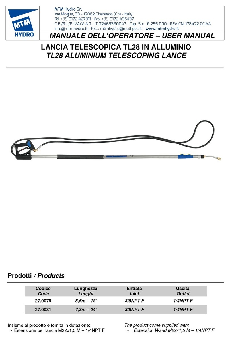
BRACCIO DOPPIO GIREVOLE INOX
S.STEEL DOUBLE ROTATING BOOM
FLESSIBILE A DUE MOLLE CON TUBO IN GOMMA
- ATTACCO A SOFFITTO
FLEXIBLE WITH 2 SPRINGS AND RUBBER HOSE
- CEILING HANG
MUM030_10 06/21
0535149808

2
CARATTERISTICHE TECNICHE
TECHNICAL CHART
* Il braccio girevole inox è stato progettato e costruito per
lavorare correttamente con acqua calda a 90°C, tuttavia può
lavorare per brevi periodi ad una temperatura massima di
120°C.
ATTENZIONE: nel caso di utilizzo del prodotto con acqua calda,
si raccomanda di porre la massima attenzione al fatto che
nell’impianto idraulico non si raggiungano pressioni e
temperature che superino i valori massimi indicati in questo
manuale.
Ove infatti, al rilascio del grilletto della pistola, il condotto di
mandata rimane in pressione e la caldaia continua a trasmettere
calore all’acqua per inerzia termica, si possono generare
aumenti dei valori suddetti. In questo caso è opportuno inserire
sempre una valvola di sicurezza per proteggere il condotto di
mandata.
DIMENSIONI DI INGOMBRO
OVERALL DIMENSIONS
* The stainless steel rotating boom has been designed and
manufactured to work properly with hot water at 190°F, although
it can operate for short periods of time at a maximum
temperature of 250 °F.
WARNING: when used in a hot water application, pay close
attention and ensure that the system does not exceed the
maximum pressure and temperature ratings listed in this user’s
manual.
This is due to the fact that, thermal inertia can cause the trapped
pressure and temperature in the system to increase and exceed
the maximum pressure and temperature rating of the boom. In
hot water applications it is always advisable to include a safety
valve to protect the unit.
Codice
Part #
Press. Max
Max Press.
(Mpa - psi)
Portata Max
Max Flow
(l/min - US/gpm)
Temper. Max
Max Temp.
(°C- °F)*
Ingressi
Inlets
Uscite
Outlets
Lunghezza
Length
(mm - inches)
1221000107
21 - 3,100
30 - 8
120 - 250
1/4” F
1/4” M
1600+1750 –63+69
1221000207
21 - 3,100
30 - 8
120 - 250
1/4” F
1/4” M
1750+2000 –69+79
1221000307
21 - 3,100
30 - 8
120 - 250
1/4” F
1/4” M
2000+2500 –79+99
1221000407
21 - 3,100
30 - 8
120 - 250
1/4” F
1/4” M
2500+2900 –99+118
1221000108
21 - 3,100
30 - 8
120 - 250
1/4” F
3/8” M
1600+1750 –63+69
1221000208
21 - 3,100
30 - 8
120 - 250
1/4” F
3/8” M
1750+2000 –69+79
1221000308
21 - 3,100
30 - 8
120 - 250
1/4” F
3/8” M
2000+2500 –79+99
1221000408
21 - 3,100
30 - 8
120 - 250
1/4” F
3/8” M
2500+2900 –99+118
Codice
Part #
X
(mm - inches)
X’
(mm - inches)
Y
(mm - inches)
Y’
(mm - inches)
1221000107
1600 - 63
1790 - 70.5
1750 - 69
1940 –76.4
1221000207
1750 - 69
1940 - 76.4
2000 - 79
2190 - 82.2
1221000307
2000 - 79
2190 - 86.2
2500 - 99
2690 - 106
1221000407
2500 - 99
2690 - 106
3000 - 118
3190 –126
1221000108
1600 - 63
1790 - 70.5
1750 - 69
1940 –76.4
1221000208
1750 - 69
1940 - 76.4
2000 - 79
2190 - 82.2
1221000308
2000 - 79
2190 - 86.2
2500 - 99
2690 - 106
1221000408
2500 - 99
2690 - 106
3000 - 118
3190 –126

3
DIMENSIONI DELLA PIASTRA DI FISSAGGIO
FIXING PLATE DIMENSIONS
mm
INSTALLAZIONE
Il braccio girevole inox deve essere adeguatamente fissato alla
struttura di supporto, in modo da evitare danni a persone e/o
cose.
La piastra di fissaggio in inox ha diversi interassi di foratura che
possono essere utilizzati con diversi tipi di vite; in ogni caso è
indispensabile utilizzare almeno due viti da M12 o in alternativa
almeno quattro viti da M10.
Il braccio ha diversi ingressi potenziali ed ha in dotazione dei
tappi; tali tappi devono essere utilizzati per chiudere gli ingressi
che non sono utilizzati.
Utilizzare del sigillante sulle connessioni filettate e serrare con
una coppia adeguata.
ATTENZIONE: il circuito in pressione dove il braccio verrà
connesso, deve essere equipaggiato con tutti i necessari
dispositivi di sicurezza nel rispetto delle norme e delle direttive
vigenti.
L’installazione deve essere effettuata da personale competente.
Il costruttore non è responsabile per danni causati da
un’installazione impropria o fatta da persone non competenti.
USO DEL PRODOTTO
Utilizzare acqua pulita e/o soluzioni di acqua con detergenti
comunemente utilizzati nei car wash;
MTM Hydro non produce o fornisce prodotti chimici per car
wash e non è responsabile dei loro effetti. Per via della grande
quantità di prodotti chimici differenti che si possono trovare sul
mercato, (con le proprie differenti reazioni chimiche), il cliente e
l’utilizzatore di questo prodotto dovrà determinare la
compatibilità dei prodotti utilizzati e valutarne gli aspetti rilevanti
in merito alle sostanze ritenute pericolose.
NOTA: Leggere sempre attentamente l’etichetta dei prodotti
chimici che si utilizzano e seguire le istruzioni.
Si raccomanda di filtrare adeguatamente l’acqua.
MANUTENZIONE
La manutenzione deve essere fatta da personale
adeguatamente preparato e competente, utilizzando ricambi
originali MTM Hydro.
Per riassemblare correttamente il prodotto, seguire il disegno
esploso presente in questa Istruzione.
Eseguire la manutenzione ordinaria del braccio rigido all’incirca
ogni 400 ore di lavoro; si raccomanda l’ispezione delle
guarnizioni e in generale di verificare l’usura dei componenti. Se
necessario sostituire i componenti usurati con parti di ricambio
originali MTM Hydro; Si raccomanda inoltre di ingrassare bene i
componenti utilizzando un grasso resistente all’acqua.
inches
INSTALLATION
The stainless steel boom must be connected to the support
structure in an appropriate manner, in order to avoid damage to
people and/or things.
The stainless steel plate has multiples holes; you can choose
the proper screws to fix the plate to the support, but please use
at least two M12 screws or at least four M10 screws as
minimum.
The boom has several inlet ports and is equipped with screw
caps; please use them to close the inlet ports unused.
Use a sealant on the caps thread and tighten them
appropriately.
WARNING: the pressure system where the boom will be
connected, must be equipped with all the safety devices (safety
valves, adjustment, etc. ...) established by current regulations.
Installation must be done exclusively by skilled workers.
The Manufacturer is not responsible or liable for any loss or
damage arising from improper installation or installation done by
unskilled workers.
PRODUCT USE
Use fresh clear water, with common detergents;
MTM Hydro does not manufacture or supply any of the
chemicals used with our product and is not responsible for their
effects. Because of the large number of chemicals that could be
used (and their different chemical reactions), the buyer and user
of this equipment should determine compatibility of the materials
used and any of the potential hazards involved.
NOTE: Always remember to carefully read the chemical
manufacturer's label and follow all directions.
We also recommend that any impure fluid be adequately filtered
before it is used.
SERVICE
Service must be done exclusively by skilled workers using only
original MTM Hydro replacement parts.
To correctly reassemble, follow the drawing listed in the
exploded view in this manual.
The rigid rotating boom’s regular service is to be done once
every 400 working hours; we recommend inspection of the seals
and internal components for wear. If necessary replace worn
components with original MTM Hydro replacement parts
lubricated with a suitable water resistant grease.

4
ATTENZIONE: Prima di eseguire la manutenzione sul prodotto
è necessario staccare l’impianto dalla rete elettrica e di
scaricare l’impianto idraulico da eventuale pressione.
Dopo lo smontaggio, i componenti devono essere correttamente
riassemblati per garantire il ripristino delle condizioni di lavoro
originarie del prodotto. Il costruttore non è responsabile dei
danni a persone e/o cose causati da una manutenzione non
corretta o effettuata da personale non qualificato.
INFORMAZIONI AGGIUNTIVE
Installare correttamente il prodotto ed eseguire la manutenzione
raccomandata e leggere attentamente le istruzioni seguendo le
avvertenza indicate sulla presente Istruzione.
Assicurarsi che queste Istruzioni siano incluse nel manuale della
macchina e/o impianto a cui il prodotto verrà installato.
L’uso improprio di questo prodotto o la sua alterazione può
causare danni a persone e/o a cose. Il costruttore non è
responsabile per ogni danno o ingiuria causata da un uso
improprio del prodotto e declina la propria responsabilità sulla
funzionalità e la sicurezza del prodotto.
I componenti decritti in questa Istruzione sono conformi alle
norme ed alle leggi vigenti come dichiarato sulla Dichiarazione
di Conformità di MTM Hydro.
MTM Hydro declina ogni responsabilità nel caso in cui le
indicazioni ed avvertenze indicate sulla presente Istruzione non
vengano seguite o rispettate.
MTM Hydro si riserva il diritto di apportare ai propri prodotti,
senza alcun preavviso, qualsiasi modifica tecnica.
DISEGNO ESPLOSO
EXPLODED VIEW
WARNING: Before performing service on the product it is
necessary to disconnect the machine from the electric net and to
discharge any residual pressure from the hydraulic system.
The components need to be properly reassembled to restore the
original conditions of the boom. The Manufacturer is not
responsible or liable for any loss or damage arising from
improper reassembly or service by unskilled workers.
ADDITIONAL INSTRUCTIONS
To correctly install, use, and service this product, carefully read
and follow the instructions and warnings contained in this
manual.
Ensure these instructions are included in the final user’s manual
of any machine in which the product is assembled.
Any improper use of or alteration of this product may cause loss
or injury. The Manufacturer is not responsible or liable for any
loss, damage, or injury arising from improper use or alteration
and declines all liability for its functioning and safety.
The component described here complies with the rules and the
lines in force that you can find in the MTM Hydro’s
CONFORMITY DECLARATION.
MTM Hydro declines all responsibility and liability in the case
that the compliance and regulations stated in this manual are
not followed or respected.
MTM Hydro reserves the right to make any modification to both
products and manuals without notice.

5
LISTA DEI COMPONENTI
COMPONENTS LIST
Kit1 Codice / *Part # 41.0023
Kit2 Codice / *Part # 41.0024
Posizione
Position
Codice
Part #
Quantità
Quantity
Kit riparazione*
Repair kit*
Descrizione
Description
1
0910026001
2
-
Tappo 1/4”
1/4”plug
2
0890665003
1
-
Piastra attacco a soffitto
Ceiling plate
3
35.0083
2
-
Prolunga ingresso acqua staffa fissa
Water inlet fitting
4
39.0100
2
-
Disco di protezione in gomma
Rubber protection disc
5
36.0195
5
-
Anello inox
S.steel ring
6
39.0136
4
Kit2
O’ring per giunto intermedio
Middle swivel o’ring
7
39.0061
2
Kit2
Anello anti estrusione per giunto intermedio
Middle sviwel back-up ring
8
39.0103
2
-
Anello in gomma anti urto
Protection rubber ring
9
39.0075
4
-
Cuscinetto radiale
Radial Bearing
10
39.0098
2
-
Protezione cuscinetto radiale
Radial bearing protector
11
1200020111
2
-
Raccordo 1/4” – 1/4”
1/4” – 1/4” fitting
12
0095256001
1
-
Girevole intermedio
Middle swivel
13
0255256005
1
-
Corpo girevole per giunto a 90°
90° swivel body
14a
30.0009
1
-
Tubo in gomma braccio 1750mm (per codici 1221000107 e 1221000108)
Rubber hose for 69” (on part #1221000107 and 1221000108)
14b
30.0010
1
-
Tubo in gomma braccio 2000mm (per codici 1221000207 e 1221000208)
Rubber hose for 79” (on part #1221000207 and 1221000208)
14c
30.0011
1
-
Tubo in gomma braccio 2500mm (per codici 1221000307 e 1221000308)
Rubber hose for 99” (on part #1221000307 and 1221000308)
14d
30.0012
1
-
Tubo in gomma braccio 3000mm (per codici 1221000407 e 1221000408)
Rubber hose for 118” (on part #1221000407 and 1221000408)
15a
1180000107
1
-
Giunto diritto da 1/4” M (per cod 1221000107, 1221000207, 1221000307,
1221000407)
1/4” M straight swivel (on part #1221000107, 1221000207, 1221000307, 1221000407)
15b
1180000108
1
-
Giunto diritto da 3/8” M (per cod 1221000108, 1221000208, 1221000308,
1221000408)
3/8” M straight swivel (on part #1221000108, 1221000208, 1221000308,
1221000408)
16
39.0102
2
-
Protezione tubo in gomma
Rubber hose protector
17a
36.0028
1
-
Struttura inox per braccio 1600mm (per codici 1221000107 e 1221000108)
S.steel flexible frame for 63” (on part #1221000107 and 1221000108)
17b
36.0025
1
-
Struttura inox per braccio 1750mm (per codici 1221000207 e 1221000208)
S.steel flexible frame for 69” (on part #1221000207 and 1221000208)
17c
36.0029
1
-
Struttura inox per braccio 2000mm (per codici 1221000307 e 1221000308)
S.steel flexible frame for 79” (on part #1221000307 and 1221000308)
17d
36.0030
1
-
Struttura inox per braccio 2500mm (per codici 1221000407 e 1221000408)
S.steel flexible frame for 99” (on part #1221000407 and 1221000408)
18a
30.0004
1
-
Tubo in gomma braccio 1600mm (per codici 1221000107 e 1221000108)
Rubber hose for 63” (on part #1221000107 and 1221000108)
18b
30.0005
1
-
Tubo in gomma braccio 1750mm (per codici 1221000207 e 1221000208)
Rubber hose for 69” (on part #1221000207 and 1221000208)
18c
30.0006
1
-
Tubo in gomma braccio 2000mm (per codici 1221000307 e 1221000308)
Rubber hose for 79” (on part #1221000307 and 1221000308)
18d
30.0007
1
-
Tubo in gomma braccio 2500mm (per codici 1221000407 e 1221000408)
Rubber hose for 99” (on part #1221000407 and 1221000408)
20a
36.0025
1
-
Struttura inox per braccio 1750mm (per codici 1221000107 e 1221000108)
S.steel flexible frame for 69” (on part #1221000107 and 1221000108)
20b
36.0029
1
-
Struttura inox per braccio 2000mm (per codici 1221000207 e 1221000208)
S.steel flexible frame for 79” (on part #1221000207 and 1221000208)
20c
36.0030
1
-
Struttura inox per braccio 2500mm (per codici 1221000307 e 1221000308)
S.steel flexible frame for 99” (on part #1221000307 and 1221000308)
20d
36.0031
1
-
Struttura inox per braccio 3000mm (per codici 1221000407 e 1221000408)
S.steel flexible frame for 118” (on part #1221000407 and 1221000408)
22
1200020100
2
-
Raccordo 1/4” – 3/8”
3/8” –3/8” fitting
23
36.0033
1
-
Rondella inox filettata
S.steel threaded washer
24
0670255003
1
-
Pistoncino per giunto a 90°
90° sviwel stem
25
39.0060
2
Kit1
Anello anti estrusione per giunto a 90°
90° sviwel back-up ring
26
0030075010
4
Kit1
O’ring per giunto a 90
90° sviwel o’ring
W
1181050110
1
-
Giunto a 90° completo
90° sviwel assembly

6
POSIZIONE DELLE GUARNIZIONI SUL GIUNTO
INTERMEDIO
SEALS POSITION ON MIDDLE SWIVEL
O-RING 46x2 NBR 70Sh
Cod. 39.0136
O-RING 46x2 NBR 70Sh
Cod. 39.0136
BK 46,8x50x1,3
Cod. 39.0061
This manual suits for next models
7
Table of contents
Other MTM HYDRO Safety Equipment manuals
Popular Safety Equipment manuals by other brands

Saxby Lighting
Saxby Lighting Nova Instruction leaflet

DBI SALA
DBI SALA Rescumatic SD-100 User instruction manual

DBI SALA
DBI SALA Sealed-Blok 3400900 User instruction manual

SKYLOTEC
SKYLOTEC SECUPIN SPA-TYP-1-L Instructions for use

Adam Hall
Adam Hall Defender Mini user manual

KIDPRO
KIDPRO Safety Net for Children installation manual