Paul Mueller Company Serving Beer Tank Effective April 25, 2018
Owner’s Manual, Part No. 9865302
Section 4.0 – Transportation and Installation (Continued)
4.6 Frame Adjustment ..................................................................................................13
4.7 Pressure Safety Valve Installation .................................................................................14
Figure 10: Securing the Pressure Safety Valve ....................................................................14
4.8 Connecting the Water Cooling System ............................................................................14
Figure 11: Water Cooling Connection ..............................................................................14
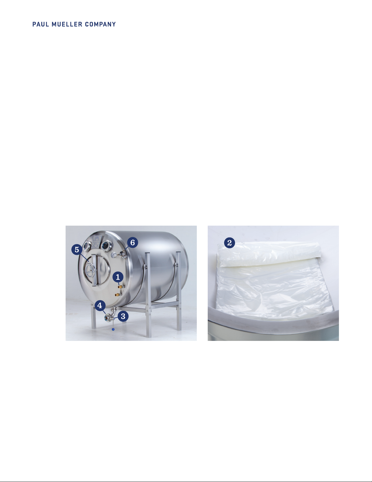
4.9 Opening the Manway ...............................................................................................15
Figure 12: Opening the Manway....................................................................................15
4.10 Inliner Installation..................................................................................................16
Figure 13: Connecting the Inliner ..................................................................................16
Figure 14: Attaching the Piercing Valve ...........................................................................17
4.11 Inliner Removal .....................................................................................................17
Figure 15: Piercing Valve Removal .................................................................................17
Figure 16: Inliner Removal .........................................................................................17
4.12 Pressurization.......................................................................................................18
Figure 17: Adjusting Tank Pressure ................................................................................18
4.13 Checking for Air Leaks in the Inliner ..............................................................................18
4.14 Cleaning the Serving Beer Tank. . . . . . . . . . . . . . . . . . . . . . . . . . . . . . . . . . . . . . . . . . . . . . . . . . . . . . . . . . . . . . . . . . . . . . . . . . . . . . . . . . . .19
Figure 18: Cleaning the Serving Beer Tank........................................................................19
4.15 Inliner Storage ......................................................................................................19
4.16 Disengaging .........................................................................................................19
Section 5.0 – Service and Parts
5.1 Service ..............................................................................................................20
5.2 Parts List ...........................................................................................................20
5.3 Ordering Replacement Parts ...................................................................................... 20
5.4 Piercing Valve .......................................................................................................21
5.5 Transit Bush for Piercing Valve ................................................................................... 22
5.6 Pressure Safety Valve .............................................................................................. 23
5.7 Sight Glass, DN50 ..................................................................................................24
5.8 Sight Glass, DN80 ..................................................................................................24
5.9 Manway............................................................................................................. 25
5.10 Beer Distributor .................................................................................................... 26
5.11 Standard Frames................................................................................................... 27
Section 6.0 – Troubleshooting
6.1 Troubleshooting Chart. . . . . . . . . . . . . . . . . . . . . . . . . . . . . . . . . . . . . . . . . . . . . . . . . . . . . . . . . . . . . . . . . . . . . . . . . . . . . . . . . . . . . . . . . . . . . 28
Table of Contents
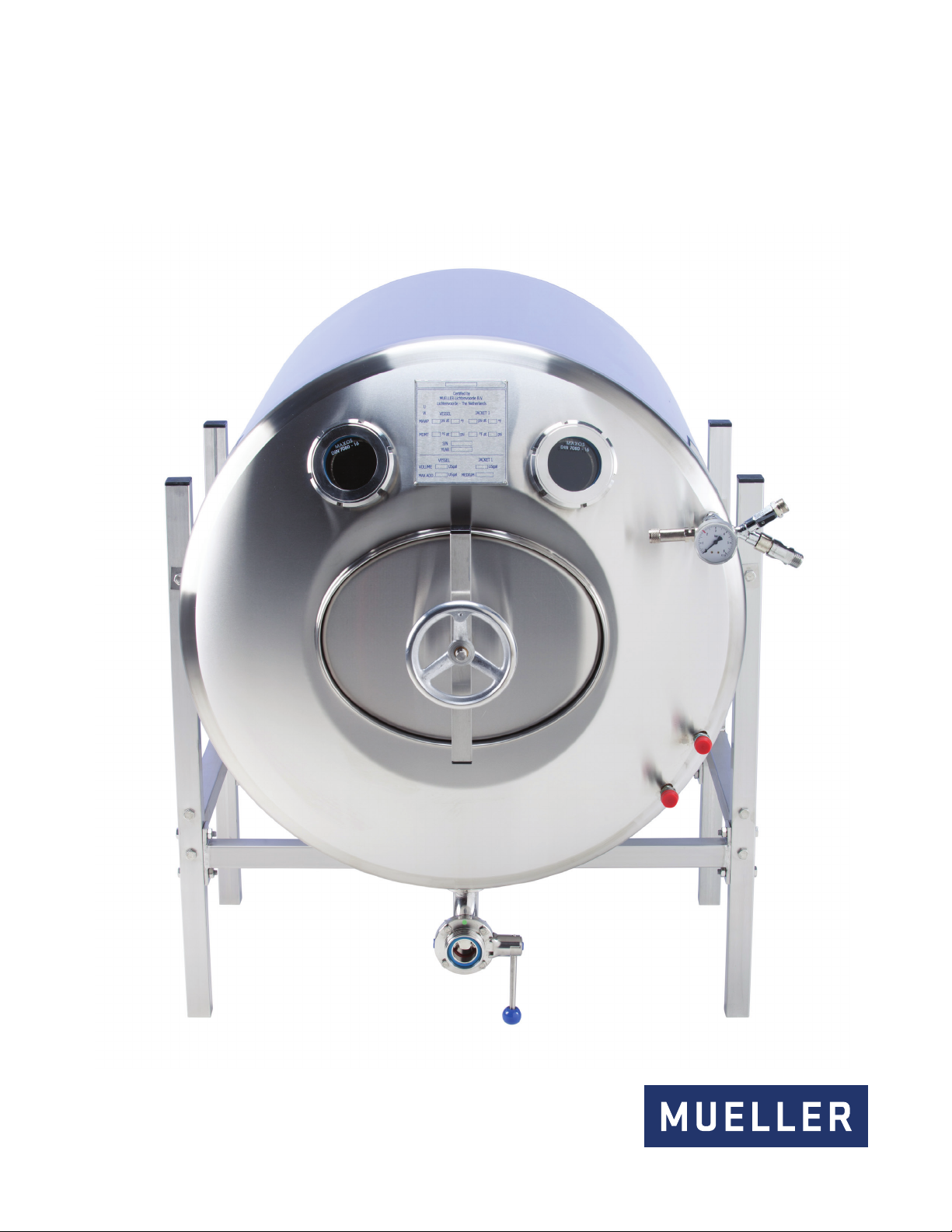
Serving Beer Tank
OWNER’S MANUAL