7.3 MESURE DE TENSION
Lisez les recommandations de sécurité avant utilisation.
Gammes de mesure automatiques 600 V DC ou AC.
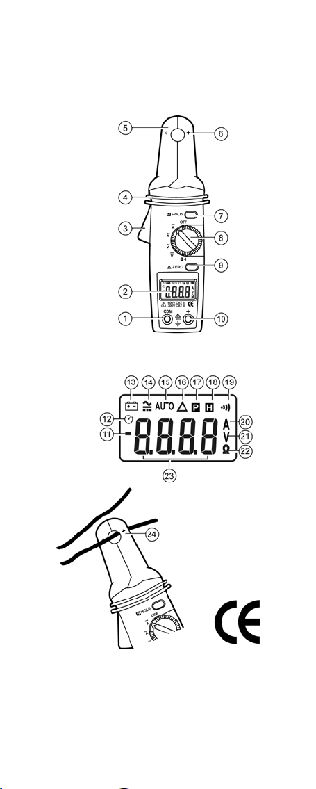
1. Positionner le sélecteur (rep. 8) sur :
- pour mesurer une tension continue.
- pour mesurer une tension alternative.
2. Insérer le connecteur noir dans la borne COM (rep. 1), le rouge
dans la borne + (rep. 10) et lire la valeur de la tension une fois
celle-ci stabilisée.
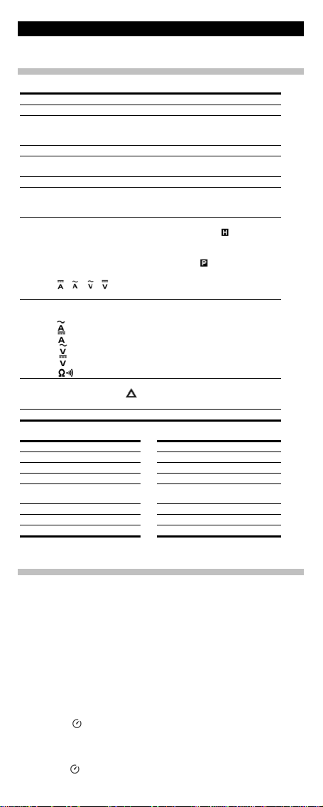
Lorsque l’icone AUTO (rep. 23) est affichée, le multimètre détermine
la gamme de mesure optimale.
Pour une tension continue, l’icone « -» (rep. 11) indique une
inversion de polarité des touches.
L’affichage de « OL » indique un dépassement de capacité.
Pour afficher la valeur crête maximale (PEAK), voir § 7.9.
Pour maintenir la valeur lue (DATA HOLD), voir § 7.10.
3. Positionner le sélecteur sur OFF.
7.4 MESURE DE COURANT CONTINU
Lisez les recommandations de sécurité avant utilisation.
Gammes de mesure automatiques de 10 ADC à 100 ADC (3 gammes).
1. Positionner le commutateur (rep. 8) sur .
2. Appuyer sur la touche ZERO (rep. 9) pour régler le zéro.
L’icone
est affichée ; la valeur est mémorisée comme valeur de
référence pour les mesures suivantes. Appuyer de nouveau sur la
touche ZERO (rep. 9) pour quitter le mode zéro.
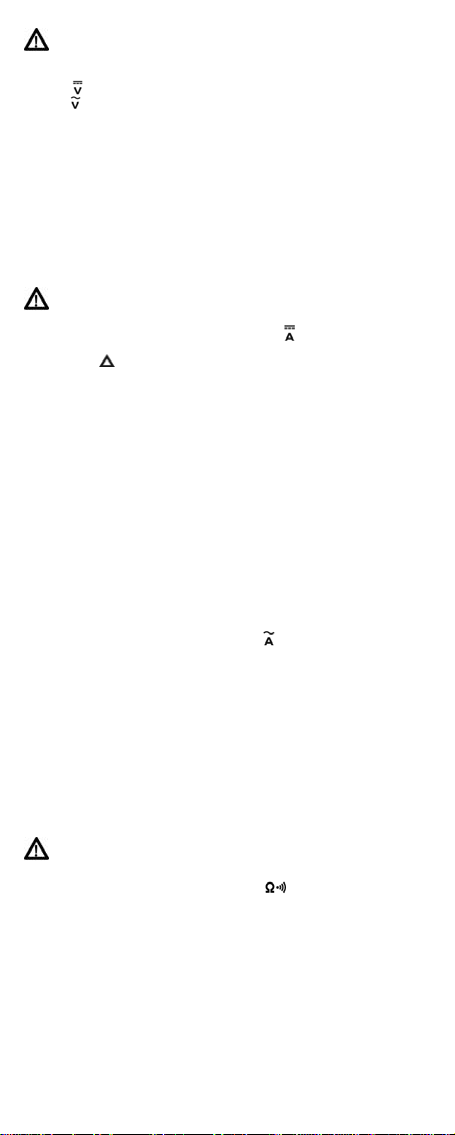
3. Appuyer sur la poignée (rep. 3) pour ouvrir la pince (rep. 5) et
placer un conducteur au centre de la pince (Fig. 3).
Nota : ne jamais insérer les deux conducteurs +et –d’un même
circuit dans la pince ; la lecture serait nulle.
4. Lire la valeur du courant une fois celle-ci stabilisée.
Avec l’icone AUTO (rep. 15) affichée, le multimètre détermine la
gamme de mesure optimale.
L’icone « -» (rep. 11) indique une inversion de polarité ; se référer au
repère « +» gravé sur la pince (rep. 6).
L’affichage de « OL » indique un dépassement de capacité.
Pour afficher la valeur crête maximale (PEAK), voir § 7.9.
Pour maintenir la valeur lue (DATA HOLD), voir § 7.10.
5. Ouvrir la pince, libérer le conducteur et positionner le sélecteur
sur OFF.
7.5 MESURE DE COURANT ALTERNATIF
Gammes de mesure automatiques de 10 AAC à 100 AAC (3 gammes).
1. Positionner le sélecteur (rep. 8) sur .
2. Appuyer sur la poignée (rep. 3) pour ouvrir la pince (rep. 6) et
placer un conducteur au centre (Fig. 3).
Nota : ne jamais placer les deux conducteurs d’un même circuit dans
la pince ; la lecture serait nulle.
3. Lire la valeur du courant une fois celle-ci stabilisée.
L’icone AUTO (rep. 15) est affichée ; le multimètre détermine la
gamme de mesure optimale.
L’affichage de « OL » indique un dépassement de capacité.
Pour afficher la valeur crête maximale (PEAK), voir § 7.9.
Pour maintenir la valeur lue (DATA HOLD), voir § 7.10.
4. Ouvrir la pince, libérer le conducteur et positionner le sélecteur
sur OFF.
7.6 MESURE DE RESISTANCE
Lisez les recommandations de sécurité avant utilisation. Le
circuit sera impérativement hors-tension.
Gammes de mesure automatiques de 0 à 10 KΩ(1 gamme).
1. Positionner le sélecteur (rep. 8) sur .
2. Insérer le cordon noir dans la borne COM (rep. 1) et le cordon
rouge dans la borne + (rep. 10) et lire la valeur.
L’affichage de OL indique un dépassement de capacité.
Avec l’icone AUTO (rep. 23) affichée, le multimètre détermine la
gamme de mesure optimale.
3. Positionner le sélecteur sur OFF.
6