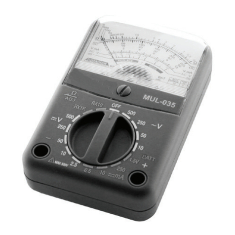
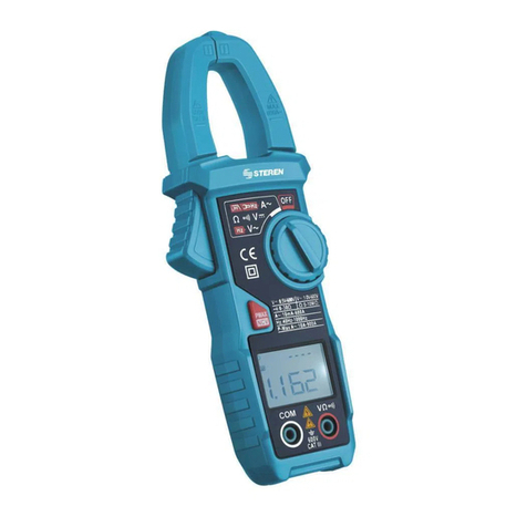
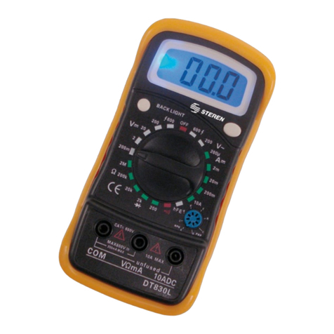
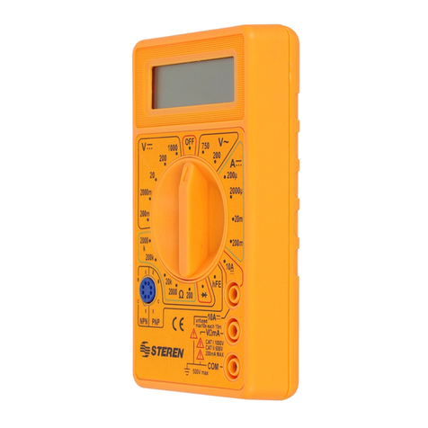
Steren MUL-105 User manual


ENGLISH
ENGLISH-2
Before using your new Analog Multimeter, please read this
instruction manual to prevent any damage. Put it away in a
safe place for future references.
INSTRUCTIONS
Checking the tester circuit, voltage meter, current meter,
resistance meter, etc. The multimeter with part number MUL-105
it’s –for many reasons- a high quality device, lightweight, and
portable. Can be use it for professionals or amateurs.
MAIN CHARACTERISTICS
1.- Audible continuity and battery tester.
2.- Capacity equivalent to a bigger device, with an excellent
resolution factor of 0,2mV and wide resistance range for
readings from 0,2 to 20M.
3.- 9V and 1,5V internal battery (2xAA)
4.- Easy control, ranges arranged by function.
5.- Make sure the testing points and the measuring terminals are
adequate for the different purposes.
HOW TO USE THE METER
When you use this meter, pay attention to polarity. The red
testing point must be connected to positive (+) and the black
testing point should be connected to negative (-).
When the voltage or current value to be measured is unknown,
set the dial to the maximum setting. Reduce level by level until
reaching the desired level.
For accurate readings, search the scale from the point where
the arrow is aligned with the maximum scale, in order to avoid a
mistake.
CALIBRATION
To set the ohm range to zero, first locate the middle button
(screw type) and with a screwdriver try to place the arrow from
the panel to zero (in the left side) then, you will find a knob in the
left side, plug the black and red testing points, put the banana
connectors together, in the Rx10 range you will see the arrow
moves to the right, use the left knob to move the arrow to zero in
the first ohm range.
Before usin
g
y
our new Analo
g
Multimeter, please read this
i
nstruction manual to prevent an
y
dama
g
e. Put it awa
y
in a
s
afe
p
lace for future references
.

ENGLISH
ENGLISH-3
SPECIFICATIONS
DC VOLTAGE
Ranges: 25,10, 50, 250 and 1000V
Full-range accuracy: ±3%
Sensitivity: 10K/V CD 25-50V
AC VOLTAGE
Ranges: 10, 50, 250, 1000V
Full-range accuracy: ±4%
Sensitivity: 4K/V
DECIBEL METER
-10 to + 22dB 0dB = 1mW/600
DC CURRENT
Ranges: 50A/ 2,5mA/25mA/250mA/10A
Full-range accuracy: ±3%
Sensitivity: 250mV
RESISTANCE
Ranges:
x1 - 0,2up to 2Kmedium range 20
x10 - 2up to 20Kmedium range 200
x100 - 20up to 200Kmedium range 2K
x1K -200up to 2Mmedium range 20K
x10 - 2Kup to 20Mmedium range 200K
Full-range accuracy: ±3%
BATTERY
1,5V
BUZZER
For continuity test
OPERATION
MEASURING RESISTANCE
1.- Connect the red testing point to the jack signaled “VmA.)))”
and the black testing point to the jack signaled “COM”.
2.- Set the dial to Ohms () range.
3.- Put the testing points together and set to 0 with the dial.

ENGLISH
ENGLISH-4
4.- Make sure that there is no voltage in the circuit before
measuring resistance.
5.- Read the ohms in the range, please refers to next table:
MEASURING DC VOLTAGE
1.- Connect the red testing point to the jack signaled +VmA .)))
and the black testing point to the jack signaled “COM”.
2.- Set the dial to the VDC setting.
3.- Connect the red testing point to positive polarity and black
testing point to negative polarity.
4.- The voltage will appear on the LCD screen. Please refers to
next table:
MEASURING AC VOLTAGE
1.- Connect the red testing point to the jack signaled “+VmA .)))
” and the black testing point to the jack signaled “COM”.
2.- Set the dial to the VAC setting.
3.- Connect the testing points to the circuit to be measured,
paying attention to polarity.
4.- The voltage will appear on the LCD screen. Please refers to
next table.
Test Position Factor
X1 X1
X10 X10
X100 X100
X1K X1000
X10K X10000
Resistance
Test Position Factor
2,5V X0,01
10V X1
50V X1
250V X1
1000V X100
DC Voltage
Test Position Factor
10V X1
50V X1
250V X1
1000V X100
AC Voltage

MEASURING DC CURRENT
1.- Connect the red testing point to the jack signaled “+VmA ”
and the black testing point to the jack signaled “COM”.
2.- Set the dial to the VAC setting.
3.- Connect the red testing point to positive polarity and black
testing point to negative polarity, in the circuit to be measured.
4.- Read the current value. Please refers to next table:
If you performs DC measures over 250mA, change the red
testing point to +10A
MEASURING DECIBELS
1.- Connect the red testing point to the jack signaled “+ VmA .
)))” and the black testing point to the jack signaled “COM”.
2.- Set the dial to the 10 VAC setting.
3.- Connect the testing points to the circuit to be measured and
read the dB value.
BATTERY TEST
1.- Connect the red testing point to the jack signaled “+ VmA .
)))” and the black testing point to the jack signaled “COM”.
2.- Set the dial to the BATT 1,5V setting.
3.- Touch the positive terminal of the battery with the red
testing point and the black testing point place it in “-“ terminal of
the battery.
CONTINUITY TEST
1.- Set the dial to the ))) setting.
2.- Connect the testing points to the circuit to be measured.
3. The buzzer will sound if the circuit is a conducer.
Dimensions: 160x88x40 mm
Weight: 277g including batteries
ENGLISH
ENGLISH-5
Test Position Factor
50AX1
2,5mA X0,01
25mA X0,1
250mA X1
10A X1
DC current
I
f
y
ou performs DC measures over 250mA, chan
g
e the red
t
estin
g
point to +10
A

REPLACING THE FUSE
Caution:
Before removing the cover from your multimeter, make sure the
testing points are disconnected to avoid the risk of electrical
shock.
1.- To replace the fuse (0,5A / 250V and 10A / 250V
respectively), remove the cover from the multimeter removing
the three screws on the back of the multimeter.
2.- Replace the fuse paying attention to polarity.
3.- Replace the cover on your multimeter.
The fuse rarely needs to be replaced and when it does, it is
usually due to an error in operation.
If “BAT” appears on your LCD screen, the battery needs to be
replaced.
To replace the battery and the fuse (15 A / 250 V), remove the
cover from the multimeter removing the three screws on the back
of the multimeter. Replace the fuse and/or battery and replace
the cover on your multimeter.
The characteristics for this multimeter are subject to change
without notice.
ENGLISH
ENGLISH-6
T
he characteristics for this multimeter are sub
j
ect to chan
g
e
wi
t
h
out not
i
ce
.


ESPAÑOL
Antes de utilizar su nuevo Multímetro Tipo Personal
Analógico, lea este instructivo para evitar cualquier mal
funcionamiento. Guárdelo para futuras referencias.
INSTRUCCIONES
Revisión del circuito probador medidor de voltaje, corriente,
resistencia, etc. El MUL-105 es por varias razones un gran
equipo en su construcción pero es a la vez un dispositivo ligero
y manejable por su tamaño, se puede usar en servicio de
campo, recomendado para usuarios ya sean aficionados o
profesionales, usted puede tener también un buen control de
éste por su duración y confiabilidad.
CARACTERISTICAS
1. Funciones para casi todo: Incluye prueba de continuidad
audible, probador de batería, etc.
2. Capacidad equivalente a la de un equipo más grande con
excelente factor de resolución de 0,2 mV y rango de resistencia
amplio para lecturas de 0,2 hasta 20M.
3. Batería interna de 9V y 1,5V ( 2 x AA )
4. El control se opera con una mano, rangos ordenados de
manera funcional.
5. Asegúrese de que las terminales de medición y puntas de
prueba sean las adecuadas.
TIPS PARA USAR TU MULTIMETRO
Cuando use éste multímetro preste particular atención para
checar la polaridad, si es negativa o positiva. La punta roja se
conecta al positivo (+), y la punta negra se coloca en el negativo
(-).
Si ha estado checando sin conocer el voltaje y corriente, use
primero el rango más alto, después el menor a éste y así hasta
que se pueda leer el valor que se desea obtener.
Para lecturas exactas, busca la escala desde el punto donde
la manecilla esté alineada con la escala extrema para evitar un
error.
CALIBRACION
Para ajustar la escala de ohms a cero primero localice el botón
central tipo cabeza de tornillo plano y con un desarmador trate
de poner la aguja del panel a cero del lado izquierdo,
posteriormente como lo es en el caso de ohms, hay una perilla
ESPAÑOL-2
A
ntes de utilizar su nuevo Multímetro Ti
p
o Personal
A
naló
g
ico, lea este instructivo para evitar cualquier mal
f
uncionamiento. Guárdelo
p
ara futuras referencias
.

ESPAÑOL
ESPAÑOL-3
de lado izquierdo lateral, inserte las puntas negro con (-) y rojo
con (+), junte las puntas de los banana y en la escala Rx10
notará que la aguja se va al extremo derecho por medio de la
perilla izquierda lateral usted podrá ajustar a cero del lado
derecho en la primer escala superior correspondiente a ohms
().
ESPECIFICACIONES
VOLTAJE DE CD
Rangos: 25,10, 50, 250 y 1000V
Exactitud a escala completa: ±3%
Sensibilidad: 10K/V CD 25-50V
VOLTAJE DE CA
Rangos: 10, 50, 250, 1000V
Exactitud a escala completa: ±4%
Sensibilidad: 4K/V
DECIBELIMETRO
-10 a + 22dB 0dB = 1mW/600
CORRIENTE CD
Rangos: 50A/ 2,5mA/25mA/250mA/10A
Exactitud a escala completa: ±3%
Caída de Voltaje: 250mV
RESISTENCIA
Rangos:
x1 - 0,2hasta 2Kmedia escala 20
x10 - 2hasta 20Kmedia escala 200
x100 - 20hasta 200Kmedia escala 2K
x1K -200hasta 2Mmedia escala 20K
x10 - 2Khasta 20Mmedia escala 200K
Exactitud a escala completa: ±3%
BATERIA
1,5V
ZUMBADOR
Para probar continuidad

ESPAÑOL
OPERACION
PRUEBA DE RESISTENCIA Ω
1. Inserte las puntas de prueba dentro de los bornes - COM y +
VmA.)))
2. Coloque el selector en el rango
3. Junte las puntas de prueba y ajuste a 0 con la perilla de
ajuste.
4. Asegúrese que no hay voltaje presente en el circuito que va a
medir.
5. Lea los en la escala y auxíliese con la siguiente tabla:
PRUEBA DE VOLTAJE CD
1. Inserte la punta de prueba roja dentro del borne +VmA .))) y
la negra dentro el borne - COM.
2. Coloque el selector en el rango de V CD
3. Conecte la punta de prueba roja a la polaridad positiva y la
negra a la negativa.
4. Lea el voltaje CD en la escala y auxíliese con la siguiente
tabla:
PRUEBA DE VOLTAJE CA
1. Inserte la punta de prueba roja dentro del borne +VmA .))) y
la negra dentro del borne - COM.
2. Coloque el selector en el rango de VCA (~)
3. Conecte las puntas de prueba al circuito para iniciar la
medición, recuerde la polaridad.
4. Lea el voltaje de CA (~) en la escala y auxíliese con la
siguiente tabla:
ESPAÑOL-4
Prueba Posición Multi
p
licador
X1 X1
X10 X10
X100 X100
X1K X1000
X10K X10000
Resistencia
Prueba Posición Multi
p
licador
2,5V X0,01
10V X1
50V X1
250V X1
1000V X100
Voltaje CD

PRUEBA DE CORRIENTE CD
1. Inserte la punta roja dentro del borne +VmA . y la negra
dentro del borne - COM.
2. Coloque el selector en el rango de A CD
3. Conecte la punta roja de prueba a la polaridad positiva del
circuito a probar y la negra a la polaridad negativa.
4. Lea la corriente en la escala de A CD y auxíliese con la
siguiente tabla:
Cuando medimos corriente de CD arriba de 250 mA cambiar
la punta de prueba roja al borne +10 A
MEDICION DE DECIBELES
1. Inserte la punta de prueba negra dentro del borne - COM y la
roja dentro del borne + VmA . )))
2. Coloque el selector en la posición de 10 V CA (V~).
3. Conecte las puntas al circuito a probar y lea en la escala roja
de dB.
PRUEBA DE BATERIA
1. Inserte la punta de prueba negra dentro del borne - COM y la
punta roja dentro del borne + VmA . )))
2. Coloque el selector en la posición BATT 1,5V
3. Toque con la punta de prueba roja la terminal “+” de la batería
(pila) y con la punta de prueba negra la terminal “-” de la batería.
ESPAÑOL-5
ESPAÑOL
Cuando medimos corriente de CD arriba de 250 mA cambia
r
l
a punta de prueba ro
j
a al borne +10 A
Prueba Posición Multi
p
licador
50AX1
2,5mA X0,01
25mA X0,1
250mA X1
10A X1
Corriente CD
Prueba Posición Multi
p
licador
10V X1
50V X1
250V X1
1000V X100
Voltaje AC

4. Lea el valor en la escala BATT, sólo verá buena o mala.
PRUEBA DE CONTINUIDAD
1. Coloque el selector en la posición zumbador )))
2. Conecte las puntas al circuito a probar.
3. El zumbador sonará si el circuito es conductor.
Dimensiones: 160X88X40 mm
Peso 277g incluyendo baterías
REEMPLAZO DE FUSIBLES
Precaución:
Para evitar choque eléctricos desconecte las puntas de prueba
antes de abrir su multímetro.
1. Retire los tornillos de la tapa del multímetro y localice los
fusibles 0,5A / 250V y 10A / 250V respectivamente, retire el
dañado y reemplácelo con uno del mismo valor.
2. Tape su multímetro.
INSTALACION DE BATERIAS
1. Con la tapa posterior retirada localice las baterías 9V y AAA
1,5 V
2. Reemplace teniendo cuidado de colocar adecuadamente la
polaridad.
3. Vuelva a colocar la tapa de su multímetro.
El diseño del producto y las especificaciones pueden
cambiar sin previo aviso.
ESPAÑOL
ESPAÑOL-6
E
l diseño del producto
y
las especificaciones pueden
c
ambiar sin
p
revio aviso
.

WARRANTY
This Steren product is warranted under normal usage against defects in
workmanship and materials to the original purchaser for one year from the date of
purchase.
CONDITIONS
1.- This warranty card with all the required information, invoice or purchase ticket,
product box or package, and product, must be presented when warranty service is
required.
2.- If the product stills on the warranty time, the company will repair it free of charge.
3.- The repairing time will not exceed 30 natural days, from the day the claim was
received.
4.- Steren sell parts, components, consumables and accesories to costumer, as well
as warranty service, at any of the addresses mentioned later.
THIS WARRANTY IS VOID IN THE NEXT CASES:
If the product has been damaged by an accident, acts of God, mishandling, leaky
batteries, failure to follow enclosed instructions, improper repair by unauthorized
personnel, improper safe keeping, among others.
a) The consumer can also claim the warranty service in the purchase establishment.
b) If you lose the warranty card, we can reissue it, if you show the invoice or
purchase ticket.
RETAILER INFORMATION
Name of the retailer
Address
Product
Brand
Part number
Serial number
Date of delivery
In case your product fails, contact a closer retailer. If you have any doubt,
please give a call to our Call Center.
Call Center
Mexico City: 53 54 22 90
Province: 01 800 500 9000

PÓLIZA DE GARANTÍA
Esta póliza garantiza el producto por el término de un año en todas sus partes y
mano de obra, contra cualquier defecto de fabricación y funcionamiento, a partir de
la fecha de entrega.
CONDICIONES
1.- Para hacer efectiva la garantía, presente ésta póliza y el producto, en donde fue
adquirido o en Electrónica Steren S.A. de C.V.
2.- Electrónica Steren S.A de C.V. se compromete a reparar el producto en caso
de estar defectuoso sin ningún cargo al consumidor. Los gastos de transportación
serán cubiertos por el proveedor.
3.- El tiempo de reparación en ningún caso será mayor a 30 días, contados a partir
de la recepción del producto en cualquiera de los sitios donde pueda hacerse
efectiva la garantía.
4.- El lugar donde puede adquirir partes, componentes, consumibles y accesorios,
así como hacer válida esta garantía es en cualquiera de las direcciones
mencionadas posteriormente.
ESTA PÓLIZA NO SE HARA EFECTIVA EN LOS SIGUIENTES CASOS:
1.- Cuando el producto ha sido utilizado en condiciones distintas a las normales.
2.- Cuando el producto no ha sido operado de acuerdo con el instructivo de uso.
3.- Cuando el producto ha sido alterado o reparado por personal no autorizado por
Electrónica Steren S.A. de C.V.
El consumidor podrá solicitar que se haga efectiva la garantía ante la propia casa
comercial donde adquirió el producto. Si la presente garantía se extraviara, el
consumidor puede recurrir a su proveedor para que le expida otra póliza de
garantía, previa presentación de la nota de compra o factura respectiva.
DATOS DEL DISTRIBUIDOR
Nombre del Distirbuidor
Domicilio
Producto
Marca
Modelo
Número de serie
Fecha de entrega
En caso de que su producto presente alguna falla, acuda al centro de
distribución más cercano a su domicilio y en caso de tener alguna duda o
pregunta por favor llame a nuestro Centro de Atención a Clientes, en donde
con gusto le atenderemos en todo lo relacionado con su producto Steren.
Centro de Atención a Clientes
Ciudad de México: 53 54 22 90
Interior de la República: 01 800 500 9000
Table of contents
Languages:
Other Steren Multimeter manuals

Steren
Steren MUL-300 User manual

Steren
Steren MUL-605 User manual

Steren
Steren MUL-016 User manual

Steren
Steren MUL-020 User manual

Steren
Steren MUL-095 User manual

Steren
Steren MUL-400 User manual

Steren
Steren MUL-010 User manual

Steren
Steren MUL-005 User manual

Steren
Steren MUL-283 User manual

Steren
Steren MUL-115 User manual
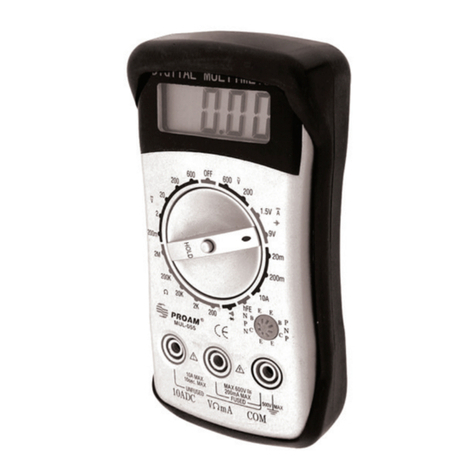
Steren
Steren MUL-100 User manual

Steren
Steren MUL-052 User manual

Steren
Steren MUL-050 User manual

Steren
Steren MUL-005 User manual
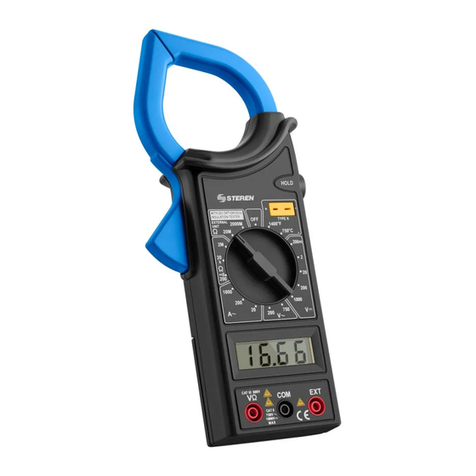
Steren
Steren MUL-030 User manual

Steren
Steren MUL-280 User manual

Steren
Steren MUL-010 User manual

Steren
Steren MUL-100 User manual
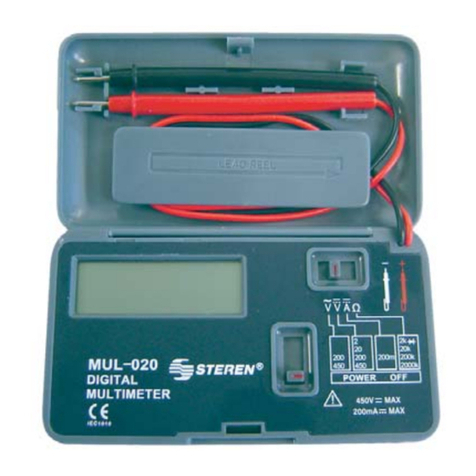
Steren
Steren MUL-282 User manual
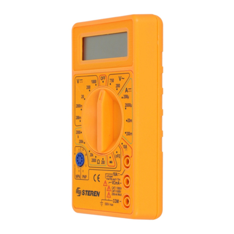
Steren
Steren MUL-055 User manual