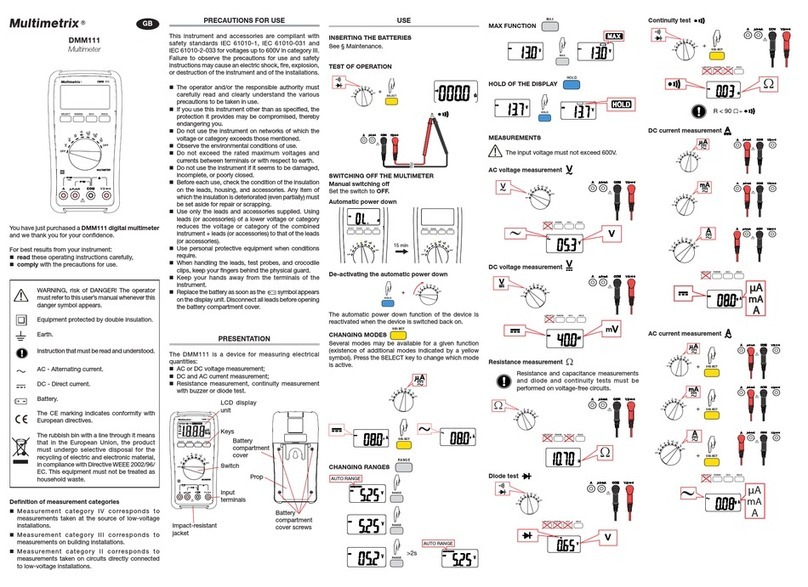
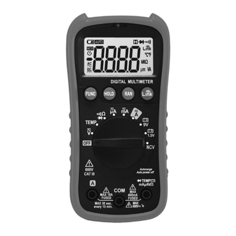
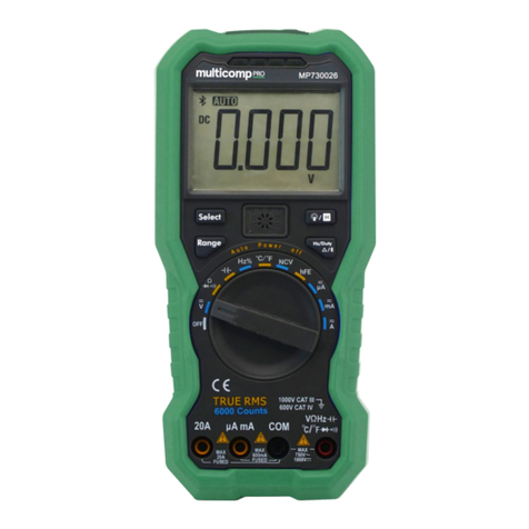
Multimetrix DMM 16 User manual

DMM 16
Multimeter
User’s manual
CHAUVIN ARNOUX
190, rue Championnet
75876 PARIS Cedex 18 -FRANCE
Tel.:+33 1 44 85 44 85 -Fax: +33146 27 7389
info@chauvin-arnoux.fr
Export:Tel.:+33 1 44 85 44 38 -Fax: +33146 27 9559
export@chauvin-arnoux.fr
694243A02-Ed. 4-07/14
PRECAUTIONS FOR USE
This device is compliant with safety standards IEC61010-1, 61010-2-032 and 61010-2-033 for
voltages up to 300V incategory III atan altitude below 2,000m, indoors, witha degree of pollution
of not more than2.
These safety instructions are intended to ensure the safety of persons and proper
operation of the device. If the device is used other than as specified in this data sheet, the
protection provided by the device may be impaired.
The operator and/or the responsible authority must carefully read and clearly
understand the various precautions to be taken in use.
If you use this instrument other than as specified, the protection it provides may be
compromised, thereby endangering you.
Do not use the instrument in an explosive atmosphere or in the presence of
flammable gases or fumes.
Do notusethe instrument on networks of whichthe voltage or categoryexceeds
those mentioned.
Do not exceed the rated maximum voltages between terminals or with respect to
earth.
Do not use the instrument if it seems to be damaged, incomplete, or poorly closed.
Before each use, check the condition of the insulation on the leads, housing, and
accessories. Any item of which the insulation is deteriorated (even partially) must
be set aside for repair orscrapping.
Use leads and accessories rated for voltages and categories at least equal to
those of the instrument. If not, an accessory of a lower category reduces the
category of the combined multimeter + accessory to that of the accessory.
Observe the environmental conditions of use.
Do not modify the instrument and do not replace components with "equivalents".
Repairs and adjustments must be done by approved qualified personnel.
Replace the battery as soon as the symbol appears on the display unit.
Disconnect all leads before opening the battery compartment cover.
Use personal protective equipment when conditions require.
Keep your hands away from the unused test probes of the device.
When handling the test probes, crocodile clips, and current sensor, keep your
fingers behind the physical guard.
Disconnect the test probes from the measurement circuit to make current
measurements.
Disconnect the test probes from the measurement circuit before changing
functions.
MEASUREMENT CATEGORIES
CAT II: Circuits directly connected to the low-voltage installation.
Example: power supply to electro-domestic devices and portable tools.
CAT III: Power supply circuits in the installation of the building.
Example: distribution panel, circuit-breakers, machines or fixed industrial devices.
CAT IV: Circuits supplying the low-voltage installation of the building.
Example: power feeders, counters and protection devices.
- 1 -
You have just acquired a DMM16 multimeter and we thank you for your confidence.
For best results from your instrument:
Read these operating instructions carefully;
Comply with the precautions for use.
Risk ofdanger. The operator agreesto refer tothese instructions
whenever this danger symbol appears.
Application or withdrawal authorized on uninsulated or bare conductors at
dangerous voltages.
Battery
The CE marking indicates conformity with European directives.
Double insulation or reinforced insulation.
Selective sorting of wastes for the recycling of electrical and electronic
equipment within the European Union. In conformity with directive WEEE
2002/96/EC: this equipment must not be treated as household waste.
DC– Direct current
AC– Alternating current
AC and DC– Alternating and direct current
Earth
Risk of electric shock
Instructions that must be read and understood
1. PRESENTATION
Le DMM16 is an instrument for measuring electrical quantities that groups the following
functions:
AC or DC voltage measurement;
Frequency measurement;
Resistance measurement, continuity measurement with buzzer, or diode test;
Capacitance measurement;
DC or AC current measurement;
- 2 -
1.1 The switch
The switch has six positions. To access the various functions, set the switch to the
corresponding positions. Each active position is confirmed by an audible signal. The
functions are described in the table below.
OFF Stop
V or V /Hz AC or DC voltage measurement/Frequency
measurement
/ / Resistance measurement, continuity
measurement with buzzer, or diode test
Capacitance measurement
120A/
120A/Hz
120A DC or AC current measurement/
Frequency measurement
60A
/
60A/Hz
66A DC or AC current measurement/
Frequency measurement
1.2 The keys of the keypad
-"SEL" (SELECT) key
Press the "SEL" key repeatedly to obtain the following functions according to the setting
of the rotary switch:
V /V DC voltage/AC voltage
/ / Resistance measurement/continuity
measurement/diode test
120A/ 120A 120A DC current measurement/120A AC current
measurement
60A/ 60A 66A DC current measurement/66A AC current
measurement
-"RANGE" key
Your multimeter has a range change function that is normally automatic but can be made
manual. When the instrument is switched on, the default mode is automatic range
change: the "AUTO" message is then displayed.
Briefly press the "RANGE" key to change to manual mode: the "AUTO" message is
then replaced by "MANU".
Successive brief presses are used to reach the desired range.
Hold the "RANGE" key down for 2 seconds to return to the automatic range change
mode: the "MANU" message reverts to "AUTO".
- 3 -

Choice of ranges (or ratings) according to function:
660.0mV/6.600V/66.00V/600.0V
660.0mV/6.600V/66.00V/600.0V
Ω
660.0Ω
6.600kΩ/66.00kΩ/660.0kΩ
6.600MΩ/66.00MΩ
6.600nF/66.00nF/660.0nF
6.600μF/66.00μF/660.0μF/6.600mF/66.00mF
-"HOLD" key
In the "HOLD" mode, the device freezes the display ofthe lastvalue measured.
Pressing the "HOLD" key briefly during a measurement freezes the display: the
message is then displayed.
A second brief press on the "HOLD" key is used to return to the normal measured
value display refresh mode: the message disappears from the display unit.
-"MAX MIN" key
In the "MAX MIN" mode, the device records the maximum and minimum values of the
measurements made. In this mode, the automatic range change does not change the
range when this mode is entered; if the maximum values exceed the display range
(indicated by the "OL" message), the appropriate higher range must be chosen manually
before reactivating the "MAX MIN" mode.
Successive brief presses on the "MAX MIN" key produce, in order, the following actions:
1st press: the device records and displays the maximum value measured. The
"AUTO" messageis replacedby "MANU"and the "MAX" message is displayed.
2nd press: the device records and displays the minimum value measured; the "MAX"
message is replaced by "MIN".
3rd press: the device records the maximum and minimum values measured
simultaneously; it is the value currently measured that is displayed; the "MAX" and
"MIN" messages blink simultaneously on the display unit.
Additional presses serve to display the values recorded one by one by reproducing the
actions of the previous successive presses.
Press the "MAX MIN" key for two seconds to exit from the mode: the "MANU", "MAX",
and "MIN" messages are replaced by "AUTO", indicating that the device once again
changes range automatically.
-"Hz" (Hertz) key
Press the "Hz" key briefly and repeatedly to obtain the following functions according to
the settingof the rotary switch:
AC voltage measured/Frequency/Duty cycle
DC voltage measured/Frequency/Duty cycle
- 4 -
120 120A AC current measured/Frequency/Duty cycle
60 66A AC current measured/Frequency/Duty cycle
NB: When the duty cycle measurement is activated, the automatic range change leaves
the range unchanged when the mode is entered: the device changes to manual range
change mode and the "MANU" message is displayed.
- " " (Backlight) key
A brief press on the "Backlight" key lights or switches off the display unit backlighting. If
not reactivated, the backlighting switches itself off automatically after approximately 60
seconds.
"REL (ZERO)" key
The "REL (ZERO)" key is used to subtract the value displayed when the key is pressed
from all subsequent measurement values and display the result of the subtraction.
This mode can be activated by a brief press on the key for all functions except the
frequency and duty cycle measurements.
When display in relative mode is activated, the automatic range change leaves the range
unchanged when the mode is entered: the device changes to manual range change
mode and the "MANU" and " " messages are displayed.
For DC current measurements, this mode is used to set the display to zero before the
current sensor is placed on the conductor in which the current is to be measured; the
message displayed for this function, in this mode, is "ZERO".
Another brief press on the key effects the return to the normal display mode; the device
returns to the automatic range change mode and the "MANU" and " " messages are
replaced by the "AUTO" message.
Any change of function by the rotary switch terminates display in the relative mode.
1.3 The display unit
- 5 -
Symbol
Description
AUTO
Automatic range change
MANU
Manual range change
(Data Hold) Freezes the display
Value displayed in relative mode
Display of the maximumand minimumvalues
ZERO
Reset forDC current measurements
Diode test function
Continuity test function
%
Unit and function Duty cycle
APO
(Auto Power Off) automatic switching off activated
DC measurement and display
AC measurement and display
Display of a negative value
Low battery indicator (battery must be replaced)
V
(Volt) unit of voltage
A
(Ampere) unit of current
(milliFarad, nanoFarad, microFarad) units of capacitance
(ohm, kilo-ohm, Megohm) unit of resistance
Hz
(Hertz) unit of frequency
The "OL" message (OverLoad) indicates an overshoot of the measurement or display
capacity.
1.4 The leads and test probes
The multimeter is equipped with two leads (red and black), each terminated by a test
probe of thesame colour.
The leads and test probes are not detachable (they are permanently connected) and,
when not in use, can be stowed in the compartments provided for them on the right side
of the device.
The tips of the test probes (once taken out of their compartments by pressing on them
with a finger), allow voltage, resistance, continuity, diode test, and capacitance
measurements.
The test probes have physical guards that show the operator where the hand grip part
ends, beyond which the fingers must not be placed.
1.5 The current sensor
The multimeter has a current sensor that makes it possible to measure a current without
having to open the circuit.
The current sensor and its lead cannot be detached (they are permanently connected);
when not in use, they can be stowed in compartments provided for them on the back of
the device.
The current sensor has a physical guard that shows the operator where the hand grip
part ends, beyond which the fingers must not be placed.
- 6 -
2. USE
2.1 Commissioning
Place the batteries supplied with the device as follows:
1. Using a cross-headed screwdriver, unscrew the screw of the compartment cover
on the back of the housing and open the cover;
2. Place the 2 batteries in their compartment, with the correct polarities;
3. Close the cover and screw it back to the housing.
2.2 Starting up and check of operation
We recommend performing this procedure at the time of commissioning and, if the device
is used only occasionally, each time it is used.
Hold the "HOLD" key down and switch the instrument on by turning the switch from
"OFF" to "Ω".
Release the "Hold" key and check that the various symbols and segments are
correctly displayed.
A brief press on the "HOLD" key restores the normal display of the selected
function;
If the device is set to the resistance measurement function ("Ω"), check that the
display indicates "A.P.O" (for auto power off), "AUTO" (for automatic range
change), "O.L" (for OverLoad), and"MΩ" (for Megohm);
Withdraw the two leads from their compartment and establish a good contact
between the metallic parts of the two test probes; the value measured and
displayed must change from "O.LMΩ" to "0.0Ω": (the value displayed may not
be exactly zero, but must remainveryclose to zero).
The instrument is operational when the various states described above have been
checked and are correct. The rotary switch can then be set to the desired function
or to "OFF" to switch the instrument off.
- 7 -

2.3 Deactivating Auto Power Off
In order to extend the life of the batteries, the device switches itself off automatically
approximately 15 minutes after it is switched on if no key or change of function has
been activated. The device warns that it is about to switch off by emitting 3 series of 2
audible beeps and, if no action is taken, then emits a long beep and switches itself off.
When the multimeter switches itself off automatically, it can be restarted in the same
configuration by pressing the "HOLD" key twice. Any other action restarts the device,
but changes its configuration.
Automatic switching off can be deactivated by holding down the "Hz", "REL", "MAX
MIN", "RANGE" or "Backlight" key while switching on. Reminder: automatic switching
off is deactivated when the instrument is in the "MAX MIN" mode.
To eliminate the slight residual drain of the batteries in the sleep mode, it is always
best to switch the device "OFF".
2.4 DC current measurement (A )
For optimum safety, current measurements oncircuitsat voltages between 300V and
600V must be made only on category III installations or on circuits of which the possible
overvoltage levels are known to be less than those of category III.
The current sensor must not be used at the same time as the test probes.
The instrument has 2 measurement ranges, selected using the rotary switch (60A and
120A).
Remove the current sensor from its compartment on the back of the device (the test
probes are stowed in their own compartment.
Switch the instrument on in the 60A or 120A setting.
Let the value displayed stabilize and briefly press the "REL (ZERO)" key to set the
value displayed to zero. It is often necessary to repeat this operation after measuring
strong currents.
Place the sensor on the cable as indicated by the locating marks (the sensor must be
perpendicular to the cable on which it is placed), see the figure below.
Read the measurement result (afterstabilization).
Display of the "-" sign in front of the numerical value indicates that the value measured
is negative: the current is flowing in the direction opposite the polarities indicated on
the sensor.
Note: best results are obtained when the cable is carefully centred and any nearby cables
are held away fromit.
- 8 -
2.5 AC current measurement (A )
For optimum safety, current measurements oncircuitsat voltages between 300V and
600V must be made only on category III installations or on circuits of which the possible
overvoltage levels are known to be less than those of category III. The current sensor
must not be used at the same time as the test probes. The instrument has 2
measurement ranges, selected using the rotary switch (60A and 120A).
Remove the current sensor from its compartment on the back of the device (the test
probes are stowed in their own compartment.
Switch the instrument on in the 60A or 120A setting.
Press the "SEL"key briefly to switch to AC current measurement; the " " symbol is
displayed instead of " ";
Place the sensor on the cable as indicated by the locating marks (the sensor must be
perpendicular to the cable on which it is placed), see the figure above.
Read the measurement result (after stabilization).
Note: best results are obtained when the cable is carefully centred and any nearby cables
are held away from it.
2.6 DC voltage measurement (V )
For optimum safety, current measurements oncircuitsat voltages between 300V and
600V must be made only on category III installations or on circuits of which the possible
overvoltage levels are known to be less than those of category III. The instrument has 4
measurement ranges: 660mV, 6,6V, 66V, 600V. The 600mV range can be used only in
the manual range change mode, by repeated presses on the "RANGE" key. The other
ranges can be usedineitherthe manual orthe automatic range change mode.
Withdraw the test probes and leads from their compartment.
Switch the instrument on in the "V" setting.
Apply the metallic part of the black test probe on the (assumed) negative part of the
circuit to be tested.
Apply the metallic part of the red test probe on the (assumed) positive part of the
circuit to be tested.
Read the measurement result (afterstabilization).
Display of the "-" sign in front of the numerical value indicates that the value measured
is negative (the testprobesare reversed withrespect tothe polarity ofthe voltage).
2.7 AC voltage measurement (V )
For optimum safety, current measurements oncircuitsat voltages between 300V and
600V must be made only on category III installations or on circuits of which the possible
overvoltage levels are known to be less than those of cat. III. The DMM16 has 4
measurement ranges: 660mV, 6,6V, 66V, 600V.
The 600mV range can be used only in the manual range change mode, by repeated
presses on the "RANGE" key. The other ranges can be used in either the manual or the
automatic range change mode.
Withdraw the test probes and leads from their compartment.
Switch the instrument on in the "V" setting.
Press the "SEL"key briefly to switchto AC voltage measurement (the " " symbol is
displayed instead of " ")
Apply the metallic part of the black testprobe onthe partof the circuit to be tested
(assumed) closest to the earth potential.
Apply the metallic part of the redtest probe on the partof the circuit to be tested
(assumed) farthest from the earth potential.
Read the measurement result (after stabilization).
- 9 -
2.8 Frequency measurement (Hz)
For optimum safety, current measurements oncircuitsat voltages between 300V and
600V must be made only on category III installations or on circuits of which the possible
overvoltage levels are known to be less than those of category III.
The instrument has 3 measurement ranges: 660,0Hz, 6,600kHz and 66,00kHz.
Measurement of the frequency of the voltage measured: start the AC voltage
measurement method, then press the "Hz" key (display of the "Hz" symbol instead of "V").
Measurement of the frequency of the current being measured: start the AC current
measurement method, then press the "Hz" key (the "Hz" symbol is displayed instead
of "A";
Read the measurement result afterstabilization.
2.9 Duty cycle measurement (%)
For optimum safety, current measurements oncircuitsat voltages between 300V and
600V must be made only on category III installations or on circuits of which the possible
overvoltage levels are known to be less than those of category III.
The measurement range is from 10% to 94.9% (50-60Hz). If there is no usable signal or if
the duty cycle is less than 10%, the display indicates "UL", and if the duty cycle is greater
than 94.9%, the display indicates "OL".
For voltage duty cycle measurements, the device switches itself to the manual range
change mode.
Measurement of the duty cycle of the voltage being measured: start the AC voltage
measurement method, then press the "Hz" key twice (the "%" symbol is displayed
instead of "V" and "MANU" instead of "AUTO");
Measurement of the duty cycle of the current being measured: start the AC current
measurement method, then press "Hz" twice ("%" is displayed instead of "A");
Read the measurement result afterstabilization.
2.10 Resistance measurement (Ω)
Resistance, continuity, diode test, and capacitance measurements must be made
only on circuits completely disconnected fromany power supply, andafter any capacitors
have been discharged.
The instrument has 6 measurement ranges: 660,0Ω, 6,600kΩ, 66,00kΩ, 660,0kΩ,
6,600MΩ and 66,00MΩ.
All of the ranges can be used with either automatic or manual range change.
Withdraw the test probes and leads from their compartment.
Switch the instrument on in the "Ω" setting.
Apply the metallic tips of the test probes to the terminals of the resistance or of the
circuit to be tested
Read the measurement result (afterstabilization).
NB: Touching the elements or circuit during the measurement may lead to erroneous
results. For resistance measurements on nonlinear circuits, it may be necessary to select
the measurement mode and the range to be usedmanually.
- 10 -
2.11 Continuity measurement (Ω)
Resistance, continuity, diode test, and capacitance measurements must be made
only on circuits completely disconnected fromany power supply, andafter any capacitors
have been discharged.
The instrument indicates continuity by emitting a steady sound when the resistance
measured is less than 50Ω.
The value displayed is the value measured in ohms.
Withdraw the test probes and leads from their compartment.
Switch the instrument on in the "Ω" setting.
Press the "SEL" key briefly until " " appears.
Apply the metallic tips of the test probes to the terminals of the resistance or of the
circuit to be tested.
Read (if necessary) the measurement result (afterstabilization).
2.12 Diode measurement (Ω)
Resistance, continuity, diode test, and capacitance measurements must be made
only on circuits completely disconnected fromany power supply, andafter any capacitors
have been discharged.
The instrument indicates the voltage across the terminals of the semiconducting junction.
Take out the test probes and leads.
Switch the instrument on in the "Ω" setting.
Press the "SEL" key briefly until the " " symbol appears
Apply the metallic tips ofthe test probes to the terminals of the diode or ofthe junction
to be tested, according to the following polarities;
1) forward direction (conducting): apply the black probe to the cathode and the red
probe to the anode.Readthe measurement result (after stabilization), see figure A
(the threshold voltage of a silicon diode is between 0.5V and 0.7V; it is between 0.2
and 0.3V for a germanium diode. High-voltage diodes, some Zener diodes, and LEDs
cannot be tested by this method).
2) reverse direction (non-conducting): apply the black probe to the anode and the red
probe to thecathode. Read the measurement result (after stabilization), see figure B
(a diode or junction in good condition causes the display of "OL").
With some types of diode, a measured value outside the stated voltage ranges does
not necessarily mean that the diode or junction is defective.
3. CHARACTERISTICS
3.1 General conditions
Temperature
23°C ± 2°C
Relative humidity
45% to 75%
Supply voltage
2,8V ± 0.3V
Frequency range of the applied signal
45-65Hz
Sine wave
pure
Peak factor of the applied AC signal
√2
Position of the conductor in the sensor
centred
Adjacent conductors
none
AC magnetic field
none
Electric field
none
- 11 -

3.2 Characteristics under the conditions of use
Display rate:approximately 3 measurements per second
The uncertainties are expressed in ± (x% L+y digit)
DC current measurement
Range
Resolution
Measurement uncertainties
Input resistance
66.00A
0.01A
2.0% +10
─
120.0A
0.1A
2.0% +5
AC current measurement
Range Resolution
Measurement uncertainties
Input resistance
45~400Hz
66.00A
0.01A
2.0% +5 ─
120.0A
0.1A
DC voltage measurement
Range
Resolution
Measurement uncertainties
Input resistance
660.0mV
0.1mV
1.0% +3 approx. 10MΩ
6.600V
0.001V
66.00V
0.01V
600.0V
0.1V
AC voltage measurement
Range Resolution
Measurement uncertainties
Input resistance
45~60Hz
60~400Hz
660.0mV
0.1mV
1.5% +5
-
approx. 10MΩ
6.600V
0.001V
1.5% +5
66.00V
0.01V
600.0V
0.1V
Resistance measurement
Range Resolution Measurement
uncertainties
Voltage
maximum
applicable
660.0Ω
0.1Ω
1.0% +5 600V
6.600kΩ
0.001kΩ
66.00kΩ
0.01kΩ
660.0kΩ
0.1kΩ
6.600MΩ
0.001MΩ
2.0% +5
66.00MΩ
0.01MΩ
3.0% +5
Continuity measurement
Range
Resolution
Observation No-load voltage
660.0Ω0.1Ω
The buzzer is
actuated at values
less than
approximately 50Ω
approx. 0.8V
- 12 -
Diode test
Range
Resolution
Measurement uncertainties
No-load voltage
2.000V
0.001V
1.0%+5
approx. 2.0V
Capacitance measurement
Range
Resolution
Measurement uncertainties
Remarks
6.600nF
0.001nF
2.5% +5 after adjustment of the
zero for the rangesfrom
6.6nF to 6.6µF
66.00nF
0.01nF
660.0nF
0.1nF
6.600μF
0.001μF
66.00μF
0.01μF
660.0μF
0.1μF
6.600mF
0.001mF
3.0% +5
66.00mF
0.01mF
Frequency measurement
Range Resolution
Measurement uncertainties
Remarks
10.0~660.0Hz
0.1Hz
0.1% +5
At values <10.0Hz,
the display indicates
00.0Hz
6.600kHz 0.001kHz 0.1% +3
66.00kHz 0.01kHz
Sensitivity
Range
Minimum input signal (sine wave)
10Hz~400Hz
400.1Hz~10.00kHz
660mV
200mV
400mV
6.6V 0.3V 0.7V
66V
1V
3V
660V
10V
20V
66A 1A 6A
120A 10A 50A
Duty cycle measurement
Range Resolution
Measurement
uncertainties
Remarks
10% ~
94.9% 0.1% 0.5% +5
no signal or a cycle less than 10%
causes the display of "UL";
A cycle greater than 94.9%, causes
the display of "OL".
For a square wave at 50/60Hz
- 13 -
3.3 Environmental conditions
Environmental conditions in use in storage
Temperature 0°C to +50°C
32°F ~ 122°F -10°C to +60°C
14°F~140°F
Relative humidity (RH) ≤80% without
condensation ≤70% without
condensation
Altitude <2.000m up to 10.000m
3.4 Constructive characteristics
Housing Rigid polycarbonate shell with moulded elastomer covering
Sensor Polycarbonate Clamping diameter: 12mm
Screen LCD display unit with blue backlighting
Dimensions: l 41xH 18mm
Dimensions H 130xL 81xP 24mm
Weight 160 g (without battery)
3.5 Supply
Batteries 2x1,5V (AAA)
Mean battery life >250 hours (without backlighting)
Auto power off delay After ≈15 min without action on the switch and/or on
the keys
3.6 Compliance with international standards
Electric safety:
Protection class
Compliant with standards IEC61010-1,
IEC61010-2-32 and IEC61010-2-33
300V CAT III.
Class 2, double insulation
Electromagnetic
compatibility
Compliant with standard EN 61326-1
Level of protection of
the housing
Housing: IP40 (according to the standard IEC60529)
- 14 -
4. MAINTENANCE
The instrument has no parts that can be replaced by personnel who are not trained and
approved. Any non-approved repair or other work, or replacement of a part by an
"equivalent", may severely compromise safety.
4.1 Cleaning
- Disconnect the unit completely and turn the rotary switch to OFF.
- Use a soft cloth, dampened with soapy water. Rinse with a damp cloth and dry rapidly
with a dry cloth or forced air.
- Dry perfectly before putting back into use.
4.2 Replacement of the batteries
The symbol indicates that the batteries are spent. When this symbol appears on
the display unit, the batteries must be replaced. The measurements and specifications
are no longer guaranteed.
To replace the batteries,proceed as follows:
1. Disconnect everything connected to the device;
2. Set the switch to OFF;
3. using a cross-headed screwdriver, unscrew the screw of the battery compartment
cover on the back of the housing and open the cover;
4. Always replace both batteries;
5. Close the cover and screw it back down.
4.3 Repair
Return the instrument to your distributor for any work to be done, whether under the
warranty or not. If you have to ship the instrument, it is best to use its original packaging
and to state as clearly as possible, in a note attached to the equipment, the reasons for
the transfer.5. WARRANTY
The equipment is warranted against defects of materials or workmanship, in accordance
with the general terms of sale. During the warranty period (1 year), the instrument must
be repaired only by the manufacturer, who reserves the right to choose between repairing
it or replacing it, entirely or partially. If the equipment is sent back to the manufacturer,
carriage is paid by the customer
The warranty does not apply in the following cases:
1. Inappropriate use of the equipment or use with incompatible equipment;
2. Modifications made to the equipment without the explicit permission of the
manufacturer’s technical staff;
3. Work done on the device by a person not approved by the manufacturer;
4. Adaptation to a particular application not anticipated in the definition of the
equipment or not indicated in the user’s manual;
5. Damage caused by shocks, falls, or floods;
6. DELIVERY CONDITION
The DMM16 multimeter is delivered in a blister pack with:
2 1.5V batteries
a user manual in several languages
- 15 -
Table of contents
Other Multimetrix Multimeter manuals
Multimetrix
Multimetrix DMM53 User manual
Multimetrix
Multimetrix DMM54 User manual

Multimetrix
Multimetrix DMM 13 User manual
Multimetrix
Multimetrix CM 605 User manual
Multimetrix
Multimetrix DMM 220 User manual

Multimetrix
Multimetrix DMM 230 User manual

Multimetrix
Multimetrix DMM 107 User manual
Multimetrix
Multimetrix DMM121 User manual

Multimetrix
Multimetrix CM603 User manual
Multimetrix
Multimetrix DMM 210 User manual

