manuals.online logo
Brands
  1. Home
  2. •
  3. Brands
  4. •
  5. MULTISPAN
  6. •
  7. Relay
  8. •
  9. MULTISPAN VR-3KN User manual

MULTISPAN VR-3KN User manual

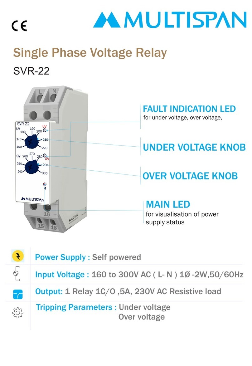
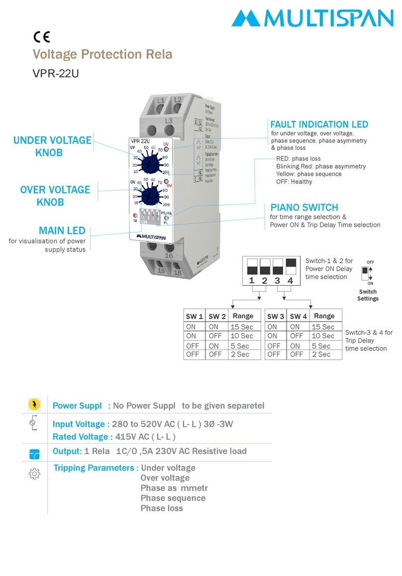
Power Supply : Self power
Tripping Parameters : Under voltage
Over voltage
Phase asymmetry
Phase sequence
Phase loss
Output: 1 Relay 2C/O ,5A 230V AC Resistive load
Input Voltage : 160 to 300V AC ( L- N ) 3Ø -4W
Voltage Protection Relay
VR-3KN
Rated Voltage : 230V AC ( L- N )
Reset Mode : Auto
UNDER VOLTGAE KNOB
TRIP DELAY KNOB
OVER VOLTAGE KNOB
RELAY STATUS LED
MAIN LED
for visualisation of power
supply status
Terminal Connection:
L1-L2
L2-L3
L3-L1
T
ON ON
P
08 07
09
TT
Phase
Loss
ON ON
< 100V AC (L-N)
Phase Loss
± 40V AC (L-L)
Phase Asymmetry
6 V
Hysteresis
= Power ON Delay (5 sec)
Over Voltage
Under Voltage
Hysteresis
Hysteresis
TP
T= Trip Delay (0 to 15 sec selectable)
(For OV & UV)
Function :
Phase Loss < 280V AC (L - L)
Phase Asymmetry ± 40V Fix (L - L)
Hysteresis : 6V Fix
Rated Voltage: 415V AC (L-L)
Delay Time :
Power ON Delay: 5 Sec.
Trip Delay : 0 to 15 Sec Selectable
(For OV & UV)
Trip Delay : <200ms (For PS & PL)
Trip Delay : 5 Sec (Asymmetry)
Recovery Time : 2 Sec
-
LED Indication:
R: Relay
UV : Under Voltage
OV : Over Voltage
PL : Phase Loss
AS : Asymentery
PS : Phase Sequence
Control Function:
Terminal Connection:
160 To 300V AC (L-N)
230V AC (L-N)
100V AC (L-N)
N
3ø-4W
VR-3KN
Read complete instructions prior to installation and operation of the unit.
WARNING : Risk of electric shock.
SAFETY PRECAUTION
All safety related codifications, symbols and instructions that appear in this operating
manual or on the equipment must be strictly followed to ensure the safety of the operating
personnel as well as the instrument.
If all the equipment is not handled in a manner specified by the manufacturer, it might
impair the protection provided by the equipment.
90.00
47.00
22.5
66.35
WARNING GUIDELINES
WARNING : Risk of electric shock.
1. To prevent the risk of electric shock, power supply to the equipment must be kept OFF
while doing the wiring arrangement. Do not touch the terminals while power is
being supplied.
2. To reduce electro magnetic interference, use wire with adequate rating and twists of the
same of equal size shall be made with shortest connection.
3. Cable used for connection to power source, must have a cross section of 1mm or greater.
These wires should have insulations capacity made of at least 1.5kV.
4. A better anti-noise effect can be expected by using standard power supply cable for the
instrument.
Dimension
90
35
90.00
35.00
62.20
59.20
MECHANICAL INSTALLATION GUIDELINES
1) To install the instrument on a DIN rail, raise the clamp at the back of the instrument
and place it on the rail. Now release the clamp, so the instrument fits on the DIN rail.
2) Ensure proper fitting of the instrument by pulling it outwards.
3) To remove the instrument raise the clamp to release it from the DIN rail.
4) The equipment in its installed state must not come in close proximity to any heating
source, caustic vapors, oil steam, or other unwanted process byproducts.
5) Do not connect anything to unused terminals.
Product improvement and upgrade is a constant procedure.
Multispan reserves the right to change specifications without prior notice.Printing and typographical errors reserved.
Multispan Control Instruments Pvt. Ltd.
72/B,Phase 1, GIDC Estate,Vatva,Ahmedabad-382445,Gujarat,India.
Ser[email protected] www.multispanindia.com
Followus
+91-9978991476/9978991474/9978991482
INSTALLATION GUIDELINES
1. This equipment, being built-in-type, normally becomes a part of main control panel and in
such case the terminals do not remain accessible to the end user after installation
and internal wiring.
2. Do not allow pieces of metal, wire clippings, or fine metallic fillings from installation to
enter the product or else it may lead to a safety hazard that may in turn endanger life or
cause electrical shock to the operator.
3. Circuit breaker or mains switch must be installed between power source and supply
terminal to facilitate power ‘ON’ or ‘OFF’ function. However this mains switch or circuit
breaker must be installed at convenient place normally accessible to the operator.
4. Use and store the instrument within the specified ambient temperature and humidity
ranges as mentioned in this manual.

Other MULTISPAN Relay manuals

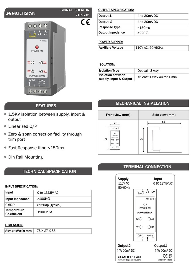
MULTISPAN VTR-632 User manual

MULTISPAN

MULTISPAN VTR-632 User manual

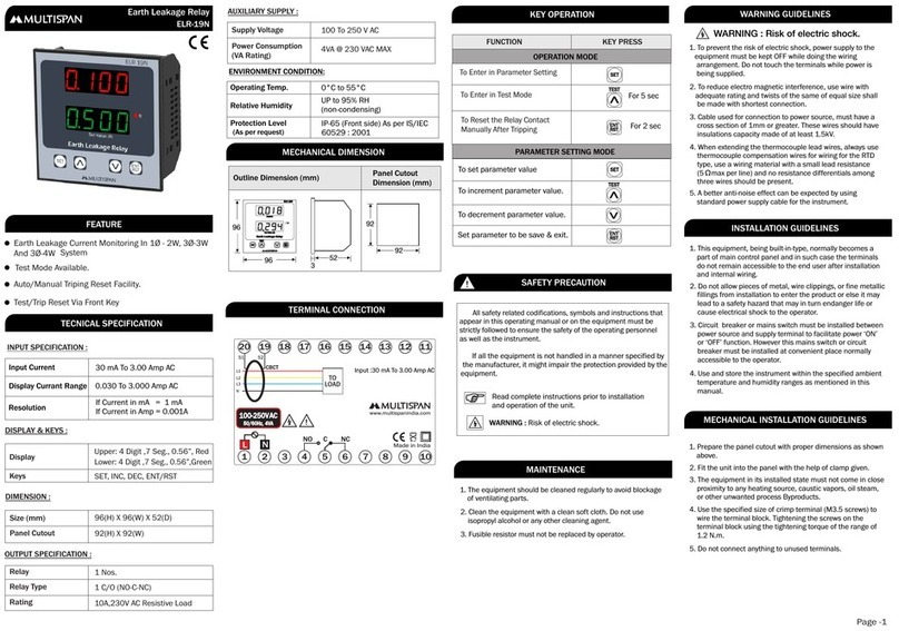
MULTISPAN ELR-19N User manual

MULTISPAN

MULTISPAN ELR-19N User manual

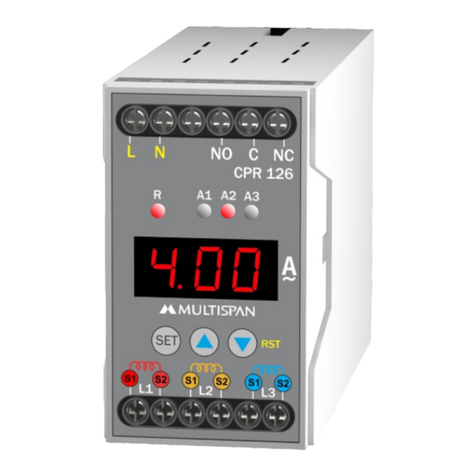
MULTISPAN CPR 126 User manual

MULTISPAN

MULTISPAN CPR 126 User manual

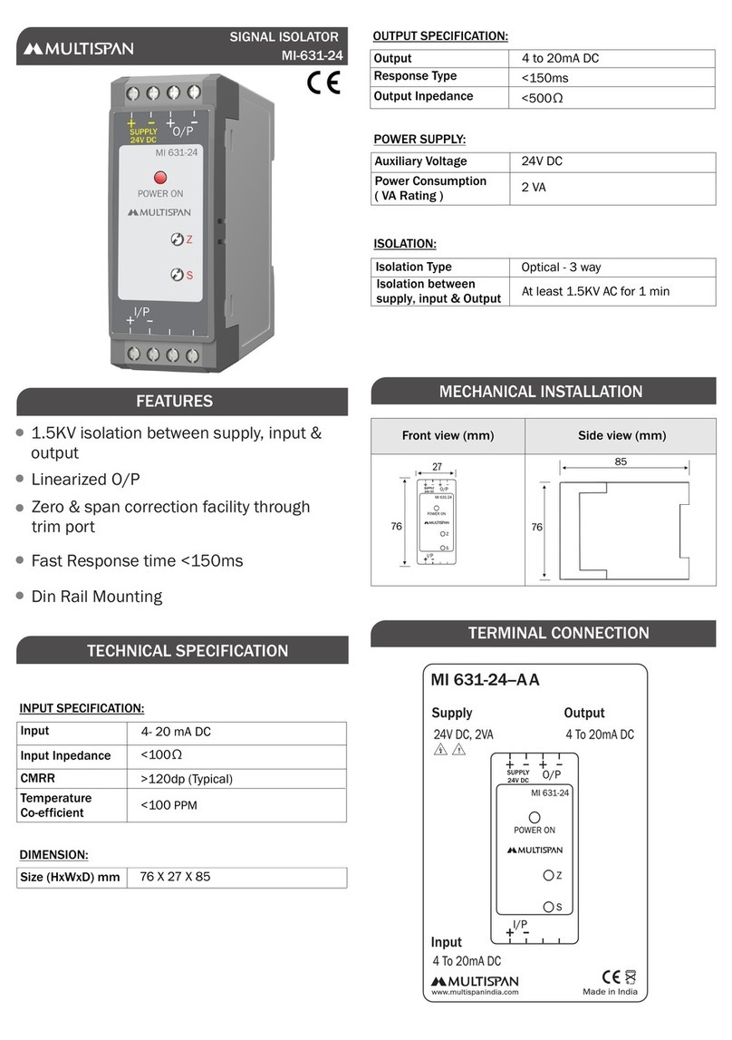
MULTISPAN MI-631-24 Instruction sheet

MULTISPAN

MULTISPAN MI-631-24 Instruction sheet

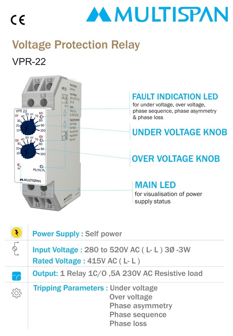
MULTISPAN VPR-22 Instruction sheet

MULTISPAN

MULTISPAN VPR-22 Instruction sheet

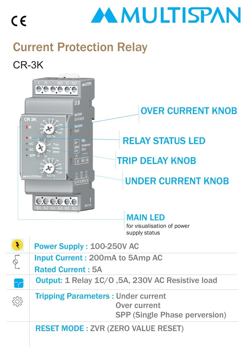
MULTISPAN CR-3K User manual

MULTISPAN

MULTISPAN CR-3K User manual

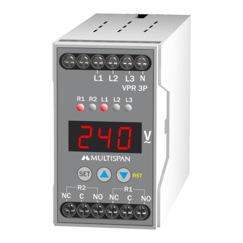
MULTISPAN VPR 3P User manual

MULTISPAN

MULTISPAN VPR 3P User manual

MULTISPAN ELR-19N User manual

MULTISPAN

MULTISPAN ELR-19N User manual

MULTISPAN VPR-22U User manual

MULTISPAN

MULTISPAN VPR-22U User manual

MULTISPAN ELR-63 User manual

MULTISPAN

MULTISPAN ELR-63 User manual

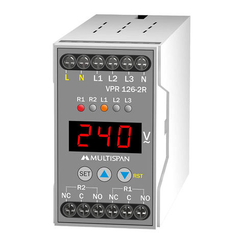
MULTISPAN VPR-126-2R User manual

MULTISPAN

MULTISPAN VPR-126-2R User manual
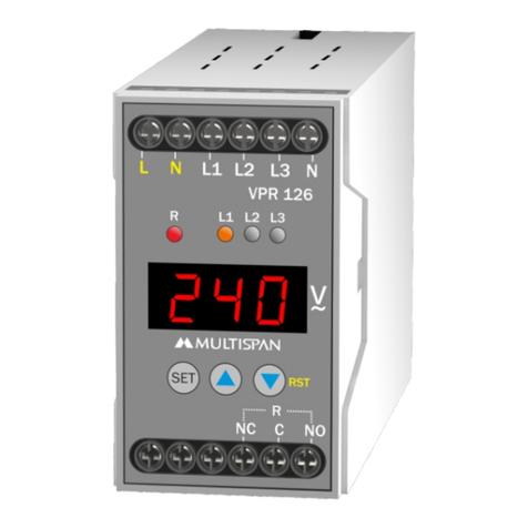
MULTISPAN VPR 126 User manual

MULTISPAN

MULTISPAN VPR 126 User manual

MULTISPAN CPR 126-1C User manual

MULTISPAN

MULTISPAN CPR 126-1C User manual

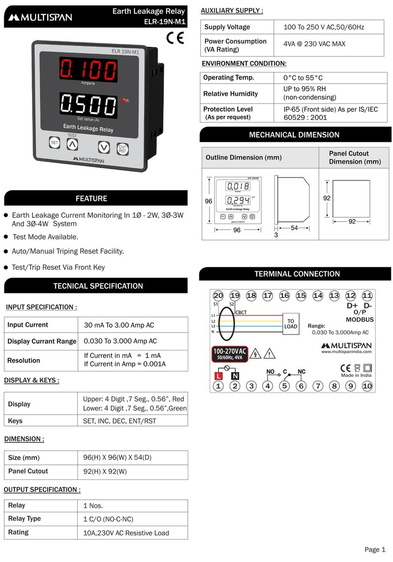
MULTISPAN ELR-19N-M1 Instruction sheet

MULTISPAN

MULTISPAN ELR-19N-M1 Instruction sheet

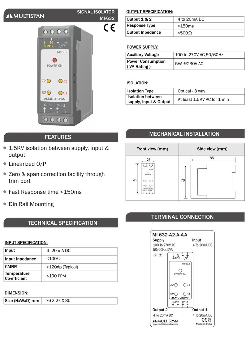
MULTISPAN MI-632 Instruction sheet

MULTISPAN

MULTISPAN MI-632 Instruction sheet

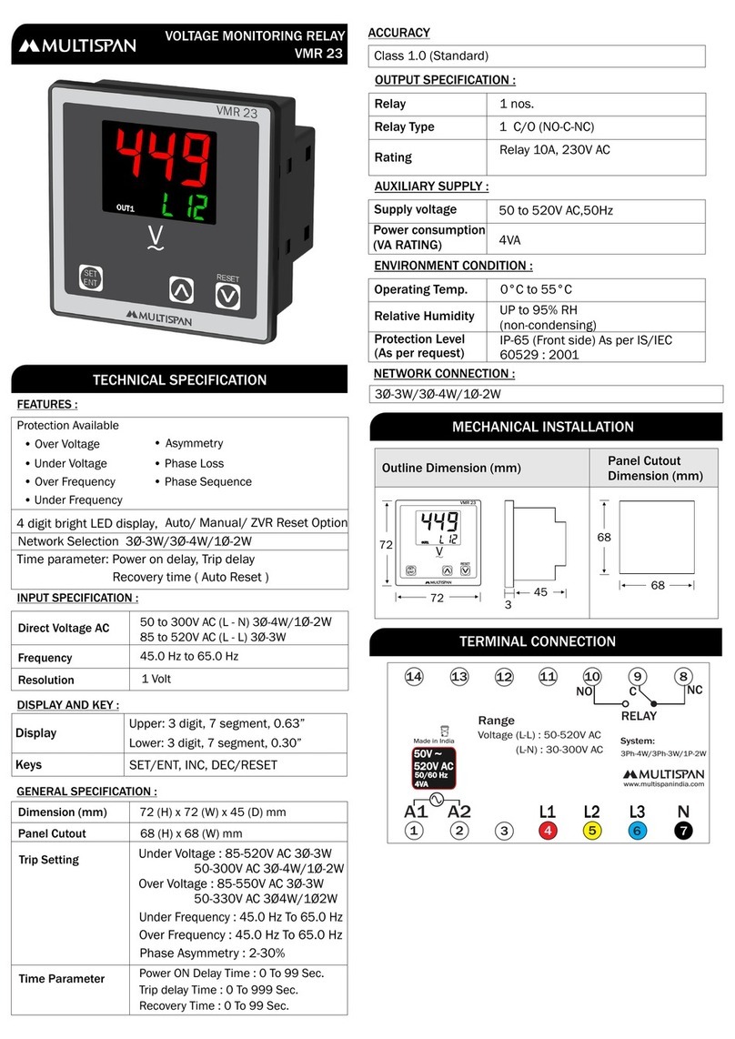
MULTISPAN VMR 23 Instruction sheet

MULTISPAN

MULTISPAN VMR 23 Instruction sheet
MULTISPAN SVR-22 Instruction sheet

MULTISPAN

MULTISPAN SVR-22 Instruction sheet

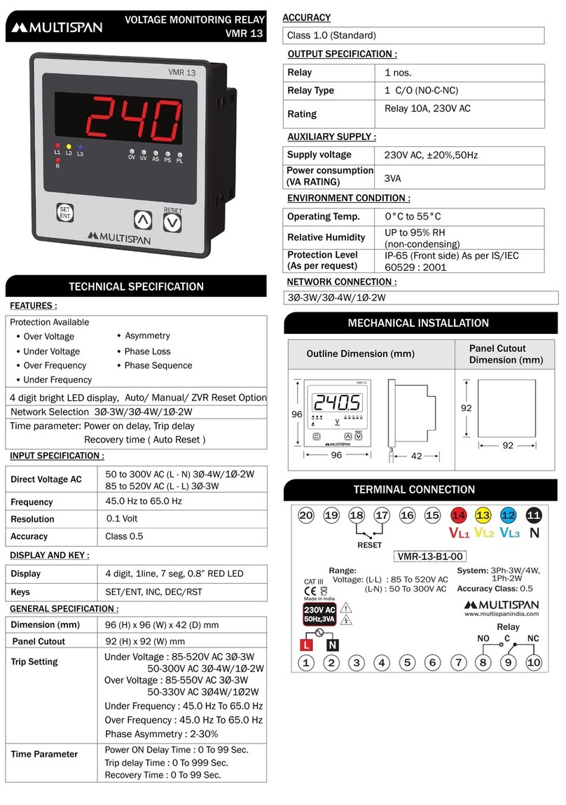
MULTISPAN VMR 13 User manual

MULTISPAN

MULTISPAN VMR 13 User manual

MULTISPAN EN-19N User manual

MULTISPAN

MULTISPAN EN-19N User manual

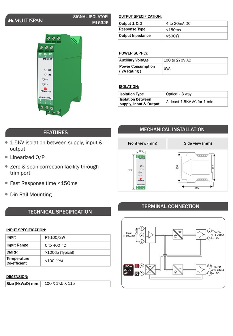
MULTISPAN MI-532P User manual

MULTISPAN

MULTISPAN MI-532P User manual

MULTISPAN MI-632-24 User manual

MULTISPAN

MULTISPAN MI-632-24 User manual

MULTISPAN VPR 3P User manual

MULTISPAN

MULTISPAN VPR 3P User manual

MULTISPAN ELR 19N-M1 User manual

MULTISPAN

MULTISPAN ELR 19N-M1 User manual

Popular Relay manuals by other brands

GE G30 instruction manual

GE

GE G30 instruction manual

Basler BE1-50-219 instruction manual

Basler

Basler BE1-50-219 instruction manual

Ice NPM800R user guide

Ice

Ice NPM800R user guide

LynTec NPAC Instruction bulletin

LynTec

LynTec NPAC Instruction bulletin

GE SPA11A instructions

GE

GE SPA11A instructions

Basler BE1-50BF instruction manual

Basler

Basler BE1-50BF instruction manual

Westinghouse KQS instructions

Westinghouse

Westinghouse KQS instructions

ABB UAF operating instructions

ABB

ABB UAF operating instructions

Elko HRN-33 manual

Elko

Elko HRN-33 manual

ABB RELION 650 SERIES installation manual

ABB

ABB RELION 650 SERIES installation manual

Basler BE1-50/51B-232 instruction manual

Basler

Basler BE1-50/51B-232 instruction manual

GE 750 instruction manual

GE

GE 750 instruction manual

AVE 44 074-W Series quick start guide

AVE

AVE 44 074-W Series quick start guide

Zennio ZVP-ACSR Technical documentation

Zennio

Zennio ZVP-ACSR Technical documentation

Shelly Plus 2PM user manual

Shelly

Shelly Plus 2PM user manual

ABB SA-1 Instruction leaflet

ABB

ABB SA-1 Instruction leaflet

ABB REL 356 quick start guide

ABB

ABB REL 356 quick start guide

LOVATO ELECTRIC DCRM 2 manual

LOVATO ELECTRIC

LOVATO ELECTRIC DCRM 2 manual

manuals.online logo
manuals.online logoBrands
  • About & Mission
  • Contact us
  • Privacy Policy
  • Terms and Conditions

Copyright 2025 Manuals.Online. All Rights Reserved.