Murphy LM500 User manual

Lube Level Maintainer
Models LM500/LM500-TF
Installation Instructions
00-02-0729
2015-05-30
Section 15

BEFORE INSTALLING THIS MURPHY PRODUCT:
•A visual inspection of this product for damage during shipping is
recommended before installation.
•It is your responsibility to ensure that qualified mechanical and electrical
technicians install this product.
•Disconnect all electrical power to the machine.
•Make sure machine cannot operate during installation.
•Follow all safety warnings of the machine manufacturer.
•Read and follow all installation instructions.
•Please contact Enovation Controls immediately if you have any questions.

Table of Contents
General Information.............................................................................................................................1
Description...........................................................................................................................1
Dimensions ..........................................................................................................................1
Range of the Snap-Switch....................................................................................................2
Test Feature.........................................................................................................................2
Thumb-ValveTM Operation....................................................................................................3
LM500 Series Flow Rates....................................................................................................3
Service Parts (Specify part number) ....................................................................................4
Hose Kit (P/N 15000355) .....................................................................................................4
Vent Fittings Kit (P/N 15000954)..........................................................................................4
Fittings Kit (P/N 15000943)..................................................................................................4
Bubble Lens Kit (P/N 15000532)..........................................................................................4
Typical Installation............................................................................................................................. 5
Mount the LM500.................................................................................................................5
Pipe Bracket Mount (PM) (P/N 15000518)...........................................................................5
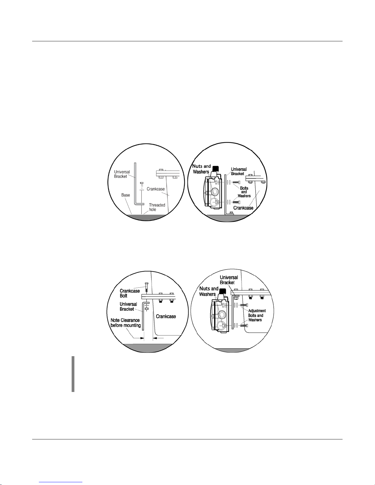
Universal Bracket Mount (UB) (P/N 15000519)....................................................................6
Base Mounting.................................................................................................................6
Crankcase (Oil Pan) Mounting.........................................................................................6
Connect Fittings and Hoses.................................................................................................7
Connect LM500 to Oil Supply Tank......................................................................................8
LM500 Typical Installation Shown........................................................................................8
Specifications..................................................................................................................................... 9

THIS PAGE INTENTIONALLY LEFT BLANK

General Information
Description
The Murphy LM500 model maintains the crankcase oil level of an engine, pump or
compressor. Adjusted to the correct running oil level, the LM500 will replenish oil as it is used.
The low level switch will alarm and/or shut down the equipment if the supply oil is lost and the
equipment continues to use oil. The LM500-TF model includes a test feature that confirms both
the float and switch are operating correctly with a single press of the test button.
Dimensions
Pipe Mount Universal Mount
Section 15 00-02-0729
2015-05-30 - 1-

Range of the Snap-Switch
This illustration shows the LM500 dial and the operating range of the switch. If level is within
the designated zones, the switch will activate.
The switch activates approximately 1/4 in. (6 mm) from the bottom of the low zone. If the level
continues to drop into the low-low zone, a shutdown will occur.
NOTE: Color zones on dial face show approximate normal operating
zones. Actual conditions may vary depending upon operating
characteristics of the engine. Placement of the LM500 according to the
above instructions will compensate for these conditions.
Test Feature
The form C (3-wire) contact allows a controller/annunciator to be wired as a closed loop
system, resulting in a reliable fault-sensitive circuit.
NOTE: Holding test button for a prolonged period of time could cause
crank case to overfill.
Section 15 00-02-0729
2015-05-30 - 2-

Thumb-ValveTM Operation
As the equipment uses oil, the float falls, providing immediate level compensation. At
the FULL position, the float holds the valve closed. If the clean oil supply is depleted
and oil level continues to fall, the low level switch will operate an alarm or equipment
shutdown.
LM500 Series Flow Rates
LM500 Series Flow Rates are based on SAE 40 motor oil @2 ft. head pressure. Friction losses
due to piping are not considered.
Section 15 00-02-0729
2015-05-30 - 3-

Service Parts (Specify part number)
Description
Part Number
Vent Fittings kit
15000954
Hose kit
15000355
1/2 NPT x1/2 in. hose barbed fitting
89080801
3/4 NPT x 1/2 in. hose barbed fitting
89081001
Pipe Bracket kit
15000518
Universal Flange kit
15000519
Hose Kit (P/N 15000355)
Quantity
Description
1
1/2 in. (13 mm) I.D. x 3 ft. (914 mm) long hose
1
1 in. (25 mm) I.D. x 3 ft. (914 mm) long hose
2
1/2 in. (13 mm) worm gear clamp
2
1 in. (25 mm) worm gear clamp
2
1/2 NPT x 1/2 in. (13 mm) barbed fitting
Vent Fittings Kit (P/N 15000954)
Quantity
Description
1
Tubing vent
1
1/4 x 1/4 NPT connector
Fittings Kit (P/N 15000943)
Quantity
Description
1
Tubing vent
1
Hose barb, 1/2 NPT to 1/2 Hose
1
Hose barb, 1in. I.D. HOSEX 3/4 NPT
1
Connector, 1/4 T x 1/2
Bubble Lens Kit (P/N 15000532)
Quantity
Description
1
Dial
1
O-ring, 0.139 C/S, 4.359 ID
6
Shoulder screw, #8-32 x 0.3125
1
Bubble lens
Section 15 00-02-0729
2015-05-30 - 4-

Typical Installation
Mount the LM500
NOTE: Mount the LM500 as close as possible to the crankcase.
CAUTION: Excessive vibration can cause overfill. Be sure mounting brackets are
supported.
The following instructions are based on the use of the pipe and universal mounting brackets shown on page 1.
Pipe Bracket Mount (PM) (P/N 15000518)
1. Mount a nominal 1/2 inch (13 mm) diameter pipe to the base of the engine.
2. Install the pipe bracket to the LM500 using the supplied fasteners, two 1/4-20 UNC x 1
inch bolts; nuts and lock washers.
3. Slip the LM500 onto the pipe and install the two adjustment bolts. Each bolt consists of
a 1/4-20 UNC x 1 inch bolt, nuts and lock washers. DO NOT tighten the adjustment
screws too tight as height adjustment might be needed later during the operation. Refer
to Connect Fittings and Hoses, for more information regarding height adjustment of the
LM500 in alignment with the oil level in the crankcase.
Section 15 00-02-0729
2015-05-30 - 5-

Universal Bracket Mount (UB) (P/N 15000519)
The universal bracket has two mounting methods: base mounting or pan mounting.
Base Mounting
1. Install the universal bracket to the base as shown using two split lock washers and two
5/16 inch diameter bolts or others as necessary.
2. Mount the LM500 to the universal bracket using the supplied fasteners, four 1/4-20 UNC
x 1-1/4 inch (32 mm) bolts; flat and lock washers. DO NOT tighten the adjustment
screws too tight as you will have to adjust the LM500 later in the installation process.
Refer to Connect Fittings and Hoses for information regarding height adjustment of the
LM500 in alignment with the oil level in the crankcase.
Crankcase (Oil Pan) Mounting
1. Install the universal bracket to the crankcase using the existing crankcase bolts.
Crankcase bolt diameter must be no larger than 7/16 inch (11 mm).
NOTE: Check clearance between crankcase and mounting bracket before
installing the mounting bracket. If space between the crankcase and
mounting bracket is narrow, attach LM500 to mounting bracket prior to
installation on crankcase.
2. Mount the LM500 to the universal bracket using the supplies fasteners, four 1/4-20 UNC
x 1-1/4 inch bolts, flat and lock washers. DO NOT tighten the adjustment bolts too tight
as height adjustment might be needed later during the operation.
Section 15 00-02-0729
2015-05-30 - 6-

3. Refer to Connect Fittings and Hoses for information regarding height adjustment of the
LM500 in alignment with the oil level in the crankcase.
Connect Fittings and Hoses
The following instructions are based on the Murphy hose kit.
1. Install the LM500 fittings in their proper locations.
NOTE: Apply a sealant such as Teflon®to all
threaded connections.
2. Attach the 1 inch (25 mm) diameter, flexible monitoring hose
to the crankcase and the monitoring port on the LM500.
CAUTION: The hose must slope slightly downward from
the LM500 and MUST NOT have any droops or low spots.
NOTE: If the drain plug on the crankcase is used for the connection, it is
recommended that a T-fitting be installed to allow draining of the
crankcase for service.
3. Install the 1/2 inch (13 mm) I.D. x 3 ft (914 mm) hose to the vent connection on the
LM500 and to the vent connection on the crankcase. The vent connection on the
crankcase must be well above the regulated oil level. All hoses must be clear of
obstructions, valleys or dips that could create liquid traps or gas/air pockets. The vent
and crankcase connections should be as straight as possible.
BEFORE CONTINUING, VERIFY THAT ALL HOSE CLAMPS ARE TIGHT.
4. Fill the crankcase to the proper oil level.
IMPORTANT: With the engine running and warm, loosen the mounting
bracket adjustment bolts and adjust the LM500 so that the oil level in the
sight gage is aligned with the middle of the green bar on the dial.
5. Tighten the adjustment bolts securely.
Section 15 00-02-0729
2015-05-30 - 7-

Connect LM500 to Oil Supply Tank
1. Remove the plug from the oil inlet connection. Be sure the removable screen inside the
connection is clear of debris. Install the oil inlet connection.
2. Connect a 1/2 inch I.D. (13 mm) or larger hose to the oil inlet fitting on the LM500 and to
the shut-off valve on the oil supply tank. Recommended minimum height above the
LM500 is 2 feet. (0.6 m); maximum 25 feet (7.7 mm). The hose must maintain a
downward slope and not have low spots or droops. Maximum head pressure rating is
9.50 psi or 25 foot oil (head pressure).
3. Before filling the supply tank with oil, be sure the tank is clean and dry and the shut-off
valve is closed. Also, be sure all hoses and clamps are tight. Fill the tank with CLEAN
oil.
WARNING: Overfill condition can be caused by excessive inlet
pressure and/or improper vent-to-crankcase installation.
4. After oil supply tank is full, open the shut-off valve.
5. Make the proper electrical connections for the application.
LM500 Typical Installation Shown
WARNING: Perform this installation using appropriate
protection. Trapped air and hot oil may cause burns.
Section 15 00-02-0729
2015-05-30 - 8-

Specifications
Crankcase Balance Vent Connection: 1/2 NPTF (top)
Inlet Connection:
1/2 NPTF removable screen (side)
Outlet Connection: 2 x 3/4 NPTF (side)
1 x 3/4 NPTF (bottom)
Thumb-ValveTM Material: Viton
Snap-switch: SPDT rating 10 A, 125 VAC; 0.5 A, 125 VDC; 10 A, 30 VDC
Wire leads: 18 AWGT x 14 in. +/- 2 in. (355 mm) length
Conduit Connection: 1/2 inch conduit (female, top). (Refer to 00-02-0735 Teflon Tape
Wrapping Technique)
Case: Die-cast aluminum
Lens: Clear frog eye non-staining, high impact, high temperature polycarbonate; UV and heat
stabilized
Dial: High visibility white background with solid green band for normal level indication
Maximum Inlet Pressure: 9.50 psi/25 ft. oil (head pressure)
Maximum Differential: 2 in. (51mm) between running and stopped
Maximum Ambient Temperature: 250oF (121oC)
Float: 304 Stainless Steel
Flow Rates: Refer to Flow Rate Chart
Section 15 00-02-0729
2015-05-30 - 9-

NOTES

NOTES

Other manuals for LM500
2
This manual suits for next models
1
Table of contents
Popular Lubrication System manuals by other brands

Coilhose Pneumatics
Coilhose Pneumatics IN-LINE Series Installation and operating instructions

BEKA
BEKA ONE 120 Assembly and operating instrustions

Wittenstein Alpha
Wittenstein Alpha LUC+125 operating manual

Gruetzner
Gruetzner LUBRICUS LUB-V user manual

SKF
SKF VSG Series Assembly instruction

GUDEL
GUDEL FlexxPump4 D operating manual

Viper
Viper Mini MKII Assembly & operation manual

Graco
Graco FIRE–BALL 300 Air Motor Muffler Kit Instructions-parts list

Perma
Perma CLASSIC manual

Norgren
Norgren Micro-Fog L73M Installation & maintenance instructions

perma-tec
perma-tec NOVA 125 operating instructions

Bijur Delimon
Bijur Delimon V5B quick start guide