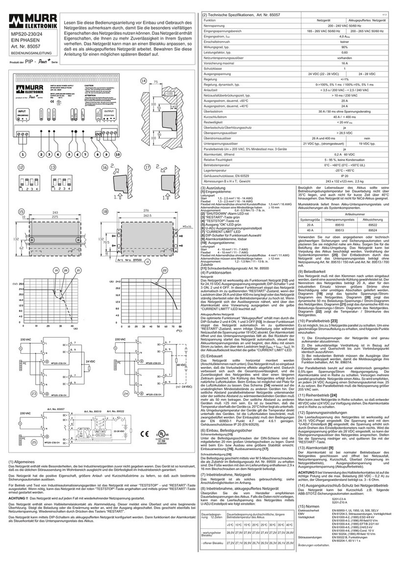
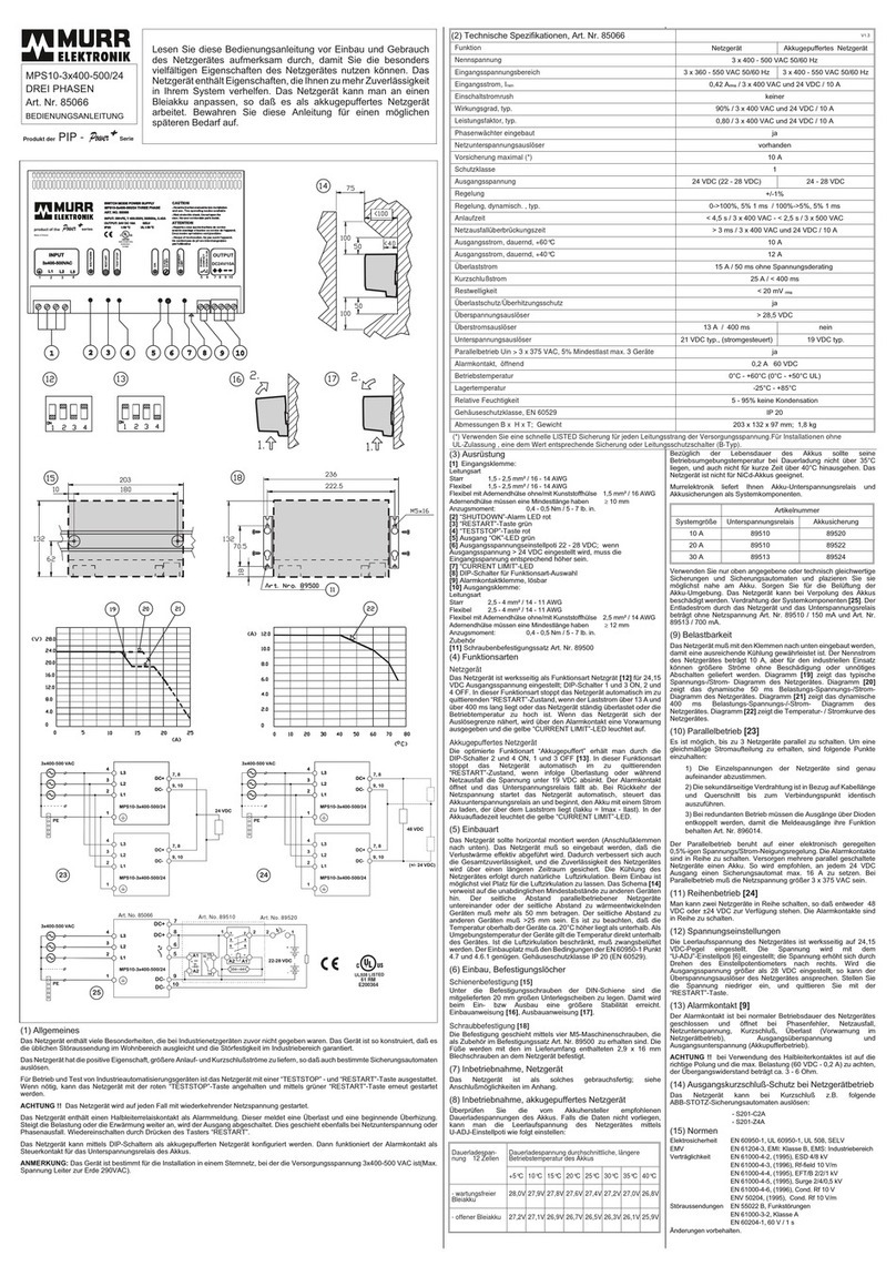
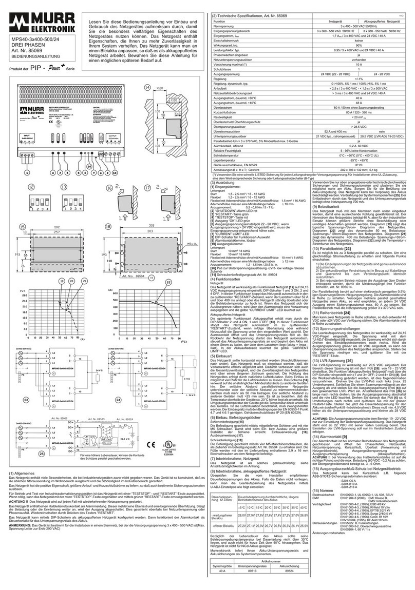
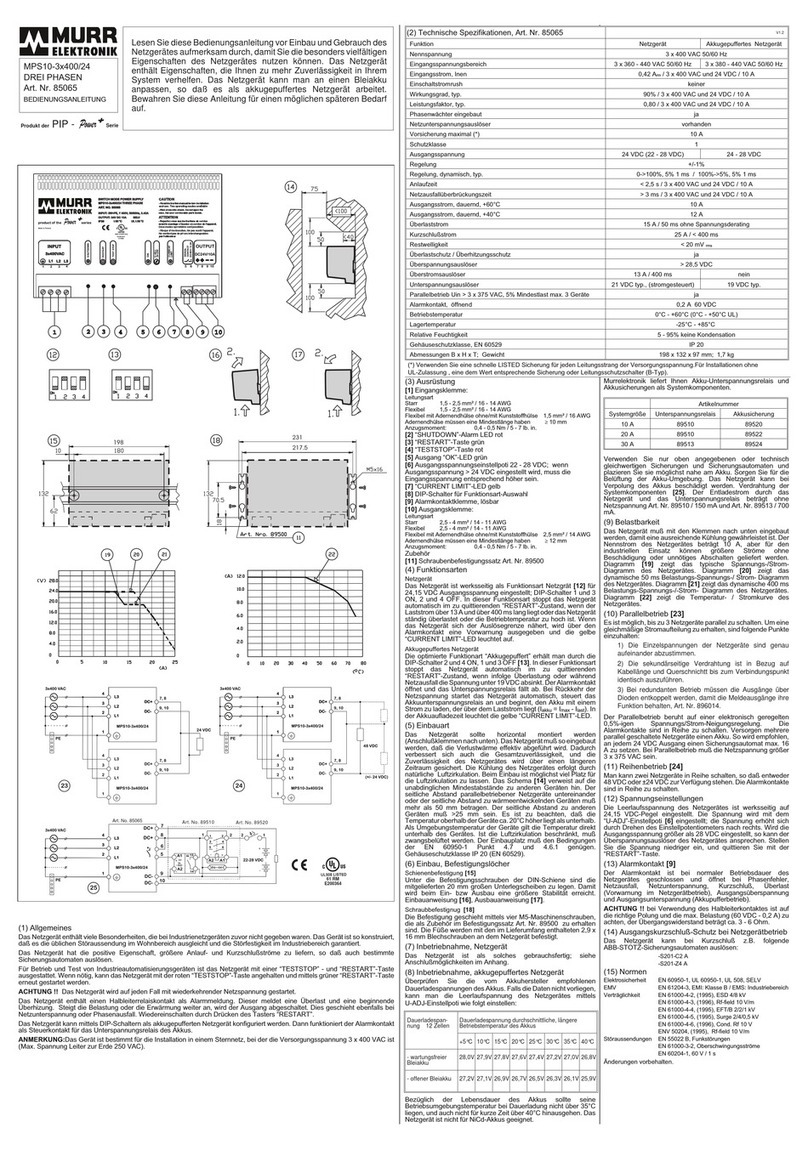
Murrelektronik Mico Pro Series User manual

MANUAL
Mico Pro®
© Murrelektronik GmbH

Murrelektronik GmbH
Falkenstraße 3
71570 Oppenweiler
GERMANY
Phone +49 7191 47-0
Fax +49 7191 47-491000
NOTE
Translation of the original instructions
Document status:
Manual number 9000-41011-0200000
Language EN
Version 2.0
Date 2019-08

User manual 9000-41011-0200000_hdb_en_20 3 / 92
This document is valid for the following products:
Mico Pro PS (power-supply)
Designation Art.-No.
Mico Pro PS 5-100-240/24 9000-41190-0000105
Mico Pro PS 10-100-240/24 9000-41190-0000110
Mico Pro PM (power module)
Power feeding module for system supply and control options
Designation Art.-No.
Mico Pro PM 24 V DC / 40 A 9000-41190-0000000
Mico Pro PD (power distribution)
Potential distributor
Designation Art.-No.
Mico Pro PD 2x12 9000-41000-0000212
Mico Pro PD 2x2x06 9000-41000-0002206
Plug-In link
Continuous jumper for distributing the supply voltage
Designation Art.-No.
Mico Pro Plug-In link 2x blue 9000-41000-0000000
Mico Pro Plug-In link 2x red 9000-41000-0000001
Mico Pro Plug-In link 1x blue and 1x red 9000-41000-0000002
Fix-Modul
Load circuit monitoring with preadjusted tripping current value
Designation Art.-No.
Mico Pro fix 1.2 9000-41011-0200000
Mico Pro fix 1.4 9000-41011-0400000
Mico Pro fix 1.4 CL2 9000-41011-0400001
Mico Pro fix 1.6 9000-41011-0600000
Mico Pro fix 1.8 9000-41011-0800000
Mico Pro fix 1.10 9000-41011-1000000
Mico Pro fix 1.16 9000-41011-1600000
Mico Pro fix 2.2 9000-41012-0200000
Mico Pro fix 2.4 9000-41012-0400000
Mico Pro fix 2.6 9000-41012-0600000
Mico Pro fix 4.2 9000-41014-0200000
Mico Pro fix 4.4 9000-41014-0400000
Mico Pro fix 4.4 CL2 9000-41014-0400001
Mico Pro fix 4.6 9000-41014-0600000
Flex-Modul
Load circuit monitoring with adjustable tripping current and channel-specific
diagnostics and control options
Designation Art.-No.
Mico Pro flex 1.10 9000-41091-0101000
Mico Pro flex 1.20 9000-41091-1102000
Mico Pro flex 2.10 9000-41092-0101000
Mico Pro flex 4.10 9000-41094-0101000

MANUAL
Mico Pro®
4 / 92
Table of Contents
1 Introduction 9
1.1 Symbols 9
1.2 Service and support 10
1.3 General notes 11
1.3.1 Purpose of this document 11
1.3.2 Applicable documents 11
1.3.3 Trademarks 11
1.3.4 Storage and transport 11
1.3.5 Environmentally friendly disposal 11
2 For your safety 13
2.1 General safety instructions 13
2.2 Qualified personnel (target group) 13
2.3 Intended purpose 13
2.4 Foreseeable misuse 13
2.5 Warranty and liability claims 14
2.6 Legal regulations 14
2.6.1 National/international legal regulations 14
3 Description 15
3.1 Product family 15
3.2 Products 16
3.2.1 Mico Pro PS (power supply) 16
3.2.2 Mico Pro PM (power module) 16
3.2.3 Mico Pro PD (power distribution) 16
3.2.4 Mico Pro Plug-In link 17
3.2.5 Mico Pro fix 18
3.2.6 Mico Pro flex 19
4 Technical Data 22
4.1 Mico Pro PS (Power Supply) 22
4.1.1 Electrical data 22
4.1.1.1 Input 22
4.1.1.2 Output 23
4.1.2 Environmental characteristics 25
4.1.2.1 Climatic 25
4.1.2.2 Mechanical 25
4.1.2.3 Electrical safety 26
4.1.2.4 EMC-interference 26
4.1.2.5 EMC-emissions 26
4.1.2.6 EMC-immunity 26
4.1.3 Protection 28
4.1.3.1 Input protections 28
4.1.3.2 Recommended Branch Circuit Protections 28
4.1.3.3 Output protections 28

MANUAL
Mico Pro®
5 / 92
4.1.3.4 Output protections with signal connector 29
4.1.4 Isolation voltages 29
4.1.4.1 Type testing 29
4.1.4.2 Routine testing 29
4.1.4.3 Field testing 29
4.1.4.4 Isolation resistance 30
4.1.4.5 PE resistance 30
4.1.5 Mechanical data 30
4.1.5.1 Materials 30
4.1.5.2 Mounting data 30
4.1.6 Product reliability 31
4.1.7 Conformity, Approvals 31
4.2 Mico Pro PM (power module) 32
4.2.1 Electrical data 32
4.2.1.1 Input 32
4.2.1.2 Control input 32
4.2.1.3 Output 32
4.2.1.4 Control output 33
4.2.2 Environmental characteristics 33
4.2.2.1 Climatic 33
4.2.2.2 Mechanical 33
4.2.2.3 Electrical safety 34
4.2.2.4 EMC-interference 34
4.2.2.5 EMC-immunity 34
4.2.3 Protection 34
4.2.3.1 Device protection 34
4.2.4 Mechanical data 34
4.2.4.1 Materials 34
4.2.4.2 Mounting data 35
4.2.5 Product reliability 35
4.2.6 Conformity, Approvals 35
4.3 Mico Pro PD (power distribution) 36
4.3.1 Electrical data 36
4.3.1.1 Input 36
4.3.1.2 Output 36
4.3.2 Environmental characteristics 36
4.3.2.1 Climatic 36
4.3.2.2 Mechanical 37
4.3.2.3 Electrical safety 37
4.3.2.4 EMC-interference 37
4.3.2.5 EMC-immunity 37
4.3.3 Protection 38
4.3.3.1 Device protection 38
4.3.4 Mechanical data 38
4.3.4.1 Materials 38
4.3.4.2 Mounting data 38
4.3.5 Conformity, Approvals 39

MANUAL
Mico Pro®
6 / 92
4.4 Mico Pro Plug-In link 40
4.4.1 Electrical data 40
4.4.1.1 Input 40
4.4.2 Environmental characteristics 40
4.4.2.1 Climatic 40
4.4.2.2 Mechanical 40
4.4.2.3 Electrical safety 40
4.4.3 Mechanical data 41
4.4.3.1 Materials 41
4.4.3.2 Mounting data 41
4.4.4 Conformity, Approvals 41
4.5 Mico Pro fix module 42
4.5.1 Electrical data 42
4.5.1.1 Input 42
4.5.1.2 Output 42
4.5.1.3 Performance record 45
4.5.2 Environmental characteristics 45
4.5.2.1 Climatic 45
4.5.2.2 Mechanical 46
4.5.2.3 Electrical safety 47
4.5.2.4 EMC-interference 47
4.5.2.5 EMC-immunity 47
4.5.3 Protection 47
4.5.3.1 Device protection 47
4.5.4 Mechanical data 48
4.5.4.1 Materials 48
4.5.4.2 Mounting data 48
4.5.5 Product reliability 49
4.5.6 Conformity, Approvals 49
4.6 Mico Pro fix CL2 module 50
4.6.1 Electrical data 50
4.6.1.1 Input 50
4.6.1.2 Output 50
4.6.1.3 Performance record 52
4.6.2 Environmental characteristics 52
4.6.2.1 Climatic 52
4.6.2.2 Mechanical 53
4.6.2.3 Electrical safety 53
4.6.2.4 EMC-interference 53
4.6.2.5 EMC-immunity 54
4.6.3 Protection 54
4.6.3.1 Device protection 54
4.6.4 Mechanical data 54
4.6.4.1 Materials 54
4.6.4.2 Mounting data 54
4.6.5 Product reliability 55
4.6.6 Conformity, Approvals 55

MANUAL
Mico Pro®
7 / 92
4.7 Mico Pro flex module 57
4.7.1 Electrical data 57
4.7.1.1 Input 57
4.7.1.2 Control input 57
4.7.1.3 Output 57
4.7.1.4 Control output 60
4.7.1.5 Performance record 60
4.7.2 Environmental characteristics 60
4.7.2.1 Climatic 60
4.7.2.2 Mechanical 62
4.7.2.3 Electrical safety 62
4.7.2.4 EMC-interference 62
4.7.2.5 EMC-immunity 63
4.7.3 Protection 63
4.7.3.1 Device protection 63
4.7.4 Mechanical data 63
4.7.4.1 Materials 63
4.7.4.2 Mounting data 63
4.7.5 Product reliability 64
4.7.6 Conformity, Approvals 65
5 Mounting 66
5.1 Installation distances 66
5.2 Installation position 67
5.3 Mounting/Dismounting 69
6 Installation 72
6.1 Overview 73
6.1.1 Mico Pro PS (power supply) 73
6.1.2 Mico Pro PM (power module) 73
6.1.3 Mico Pro PD (power distribution) 74
6.1.4 Mico Pro fix 74
6.1.5 Mico Pro flex 74
6.2 Terminal 75
6.3 Connecting cable 76
6.3.1 Mico Pro PS (power supply) 76
6.3.2 Mico Pro PM (power module) 76
6.3.3 Mico Pro fix and flex 76
7 Operation 77
7.1 Overview 77
7.1.1 Mico Pro PS (power supply) 77
7.1.2 Mico Pro PM (power module) 78
7.1.3 Mico Pro PD (power distribution) 78
7.1.4 Mico Pro fix 79
7.1.5 Mico Pro flex 80

MANUAL
Mico Pro®
8 / 92
7.2 Adjust 80
7.2.1 Mico Pro fix 80
7.2.2 Mico Pro flex 81
7.3 Module/device 82
7.3.1 Mico Pro fix and flex 82
7.4 Control and signals 83
7.4.1 Mico Pro PS / Mico Pro PM 83
7.4.2 Mico Pro fix 84
7.4.3 Mico Pro flex 84
7.5 Diagnostic 87
7.5.1 Mico Pro PS (power supply) 87
7.5.2 Mico Pro PM (power module) 87
7.5.3 Mico Pro fix and flex 88
7.6 Maintenance and cleaning 88
8 Appendix 89
8.1 Components 89
8.2 Accessories 90
8.2.1 Legal notes 90

Introduction
User manual 9000-41011-0200000_hdb_en_20 9 / 92
1 Introduction
1.1 Symbols
This document includes information and notes that have to be observed for
your own safety and to avoid injuries and material damage. They are marked
as follows:
DANGER!
Immediate danger
Failure to observe this warning involves an imminent risk of death or seri-
ous injuries.
WARNING!
Possible danger
Failure to observe this warning can lead to death or serious injuries.
CAUTION!
Low-risk danger
Failure to observe this warning can lead to mild to moderate injuries.
NOTICE
Possible material damage
Failure to observe the warning may cause damage to the device and/or
the system.
NOTE
Other technical information and notes of Murrelektronik GmbH.
RECOMMENDATION
Notes with this symbol are recommendations of Murrelektronik GmbH.
PRODUCTS AND ACCESSORIES
This symbol indicates accessories or product recommendations.
Instruction for use An arrow marks instructions.
Read and observe the instructions.
1 | If they are numbered, it is absolutely necessary to follow them in the cor-
rect order.
2 | Read and observe the instructions.

Introduction
User manual 9000-41011-0200000_hdb_en_20 10 / 92
1.2 Service and support
Service and support
Sales Our sales staff in-house and in the field, and our technicians will support you
at all times.
Sales support Our sales support will assist you:
with consultation during the development phase of your application,
with extensive system design across all product groups,
with visits from traveling sales representatives,
with a system analysis.
For any further questions, please do not hesitate to contact our sales repre-
sentatives!
Application support Our application support will assist you:
with product-related questions during commissioning,
with product-related and customer-specific software components support-
ing your application, such as diagnostics.
For any further questions, please do not hesitate to contact our sales repre-
sentatives!
Customer Service Cen-
ter (CSC)
Our staff of the Customer Service Center will help you with all questions con-
cerning installation and start-up. They support you, for example, if you have
problems with combining hardware and software products from different man-
ufacturers.
A number of support tools and measurement facilities are available for field
bus systems and EMC interference.
Call us on +49 7191 47-2050 or send us an
e-mail to: support@murrelektronik.com
Service addresses Murrelektronik GmbH has a policy of customer proximity, both at the national
and international level. Please visit our website to find your contact person:
www.murrelektronik.com

Introduction
User manual 9000-41011-0200000_hdb_en_20 11 / 92
1.3 General notes
1.3.1 Purpose of this document
Purpose of this docu-
ment
This document describes the use of the system Mico Pro. It instructs the tech-
nical staff of the machine manufacturer or machine operator on the assembly,
parameterization, electrical installation, commissioning as well as operation of
the system Mico Pro. It does not instruct on how to operate the machine into
which the system Mico Pro is integrated or will be integrated. For such infor-
mation refer to the operating manual of the machine.
1.3.2 Applicable documents
1.3.3 Trademarks
Trademarks of the following companies and institutions are used in this docu-
mentation:
1.3.4 Storage and transport
1.3.5 Environmentally friendly disposal
Comply with
country-specific
waste disposal regula-
tions.
Always dispose of scrap devices in compliance with the valid
country-specific regulations for waste disposal
(e.g., the European Waste Code 16 02 14).
Only qualified persons
may sort scrap materi-
als.
Proceed with caution when dismantling the device since you could injure
yourself.
Sort the separated components into the correct recycling line.
Document Art.-No. Location
Operating instruction
Mico Pro PS
9000-41190-0000105
Included in the scope of delivery or
downloadable from
http://shop.murrelektronik.com
Operating instruction
Mico Pro PM
9000-41190-0000000
Operating instruction
Mico Pro PD
9000-41000-0000212
Operating instruction
Mico Pro fix
9000-41011-0200000
Operating instruction
Mico Pro fix CL2
9000-41011-0400001
Operating instruction
Mico Pro flex
9000-41091-0101000
Murrelektronik
GmbH
Mico Pro®
EPLAN EPLAN Software & Service GmbH & Co. KG

Introduction
User manual 9000-41011-0200000_hdb_en_20 12 / 92
Disposal
The product can be returned to Murrelektronik GmbH free of charge for dis-
posal. The same is true for the original packaging and any batteries or power
packs. Any units that have been contaminated with hazardous substances will
not be accepted for repair or disposal.
Returns
Label the product and the packaging with
"For disposal".
Package the product.
Send the package to:
Murrelektronik GmbH
Falkenstraße 3
71570 Oppenweiler | GERMANY
We will make sure that the items are disposed of in accordance with German
legislation. The most recent owner is responsible for transport to the return
point until items arrive at their destination.

For your safety
User manual 9000-41011-0200000_hdb_en_20 13 / 92
2 For your safety
Safety for you and peo-
ple around you!
Read this chapter carefully.
Only then can you work with the device.
Use of the device Comply with all safety and accident prevention regulations when conduct-
ing project engineering, installation, startup, operation, and testing of the
device.
Check material resistance if aggressive media are used.
NOTE
Interventions in the hardware and software of the device dare, if they are not
described in this document, only be carried out by qualified personnel from
Murrelektronik GmbH.
NOTE
The operating instructions must be always available to the operator of the ma-
chine where the device is used.
2.1 General safety instructions
Note:
the relevant safety and accident prevention regulations
the EU Directives which apply to your application or national regulations
generally recognized safety rules
2.2 Qualified personnel (target group)
The Mico Pro system may only be mounted, put into operation and operated
by qualified personnel.
Personnel is considered qualified if they meet the following requirements:
The personnel have undergone appropriate technical training.
Have been trained for the operation of the machine/system as well as the
relevant safety regulations.
Have access to the manual and the other applicable documents
(see 1.3.2 "Applicable documents").
Are familiar with the safety standards which are common practice in auto-
mation engineering.
2.3 Intended purpose
The power supply unit is designed and manufactured for:
Industrial use.
Operation within the specified environmental conditions.
Installation in a control cabinet.
2.4 Foreseeable misuse
Avoid misuse! Operate the Mico Pro system only in technically perfect condition.
Ensure that only qualified and authorized personnel works with/on the sys-
tem.

For your safety
User manual 9000-41011-0200000_hdb_en_20 14 / 92
Do not alter the design, engineering, or electrical features of the connect-
ed devices.
Use the Mico Pro system only in the application fields described in this
manual and other applicable documents.
(see 1.3.2 "Applicable documents")
Use the Mico Pro system only with components approved by Murrelek-
tronik.
2.5 Warranty and liability claims
Warranty and liability claims shall be lost if
the Mico Prosystem is not used according to its designated use,
damage is caused because the manual and other applicable documents
have not been observed (see 1.3.2 "Applicable documents"),
the personnel was/is not qualified.
2.6 Legal regulations
2.6.1 National/international legal regulations
Murrelektronik GmbH herewith declares that the products and systems comply with
the basic requirements and directives:
2014/30/EU Electromagnetic compatibility
2011/65/EU RoHS

Description
User manual 9000-41011-0200000_hdb_en_20 15 / 92
3 Description
Maximum
system expansion
NOTE
The maximum possible expansion of the Mico Pro system depends on the fol-
lowing points:
Maximum operating current of 40 A per Mico Pro power module (PM).
Maximum of 40 Mico Pro modules, including Mico Pro power module
(PM).
Maximum of 3 Mico Pro power modules (PM).
Scope of delivery
NOTE
Mico Pro continuous jumpers and designation labels are not included in the
scope of delivery.
Accessories are listed in the appendix.
3.1 Product family
Mico Pro is a modular system consisting of electronic auxiliary current switches and a power module
for current monitoring
Special features of the product family:
System with modular structure
Innovative bridging concept
See accessories
Adjustable or fixed tripping current
Integrated 0-V wiring concept
Enormous space saving
Potential distributor for connecting several loads to
a Mico Pro channel
Cascading of two Mico Pro load circuit monitoring one
after the other
Channel-specific or system-integrated control inputs
and outputs (Mico Pro flex)
Channel-specific switching function via CTRL input
(Mico Pro flex)
Quick connection with push-in spring-clamp terminals
Manual connection and disconnection of channels via
buttons
Operating state memory device
Mico Pro system components:
1PM module (power module) or
PS module (power supply)
Power feeding module for system supply and
control options
2Fix module
Load circuit monitoring with preset tripping
current
3Flex module
Load circuit monitoring with adjustable tripping
current and channel-specific diagnostics and
control options
4PD module (power distribution)
Potential distributor
5Plug-In link
Continuous jumper for distributing the supply
voltage
6Cover plate
Left and right
Fig. 3-1: Example of assembly

Description
User manual 9000-41011-0200000_hdb_en_20 16 / 92
3.2 Products
3.2.1 Mico Pro PS (power supply)
3.2.2 Mico Pro PM (power module)
NOTE
The cover plates for the left and right sides are attached to this module.
3.2.3 Mico Pro PD (power distribution)
Mico Pro Power-Supply (PS)
Designation Article number Function
Mico Pro PS
5-100-240/24
9000-41190-0000105 Nominal voltage:
100 V ... 240 V
Voltage range:
90 V ... 265 V
Mico Pro PS
10-100-240/24
9000-41190-0000110 Nominal voltage:
100 V ... 240 V
Voltage range:
90 V ... 265 V
Mico Pro power module (PM)
Power feeding module for system supply and control options
Designation Article number Function
Mico Pro PM
24 V / 40 A
9000-41190-0000000 Operating voltage:
12 V , 24 V
Input voltage range:
9 V ... 30 V
Total operating current
≤40 A
Control inputs and outputs
Mico Pro power distribution module (PD)
Potential distributor
Designation Article number Function
Mico Pro PD 2x12 9000-41000-0000212 Operating voltage potential
12 clamps
GND / 0 V potential
12 clamps
Mico Pro PD 2x2x06 9000-41000-0002206 Group 1
Operating voltage potential
6 clamps
GND / 0 V potential
6 clamps
Group 2
Operating voltage potential
6 clamps
GND / 0 V potential
6 clamps

Description
User manual 9000-41011-0200000_hdb_en_20 17 / 92
3.2.4 Mico Pro Plug-In link
Model overview
Mico Pro Plug-In link Continuous jumper for distributing the supply voltage
Designation Article number Function
Mico Pro Plug-In link
2x blue
9000-41000-0000000 2 pieces
Color: blue
Total operating current continuous jumper: ≤40 A
Length: 500 mm
Mico Pro Plug-In link
2x red
9000-41000-0000001 2 pieces
Farbe: red
Total operating current continuous jumper: ≤40 A
Length: 500 mm
Mico Pro Plug-In link
1x blue and 1x red
9000-41000-0000002 1 piece blue and 1 piece red
Color: blue and red
Total operating current continuous jumper: ≤40 A
Length: 500 mm
Mico Pro Plug-In link
1x blue 1x red 250
9000-41000-0000003 1 piece blue and 1 piece red
Color: blue and red
Total operating current continuous jumper: ≤40 A
Length: 250 mm

Description
User manual 9000-41011-0200000_hdb_en_20 18 / 92
3.2.5 Mico Pro fix
Model overview
Mico Pro fix load circuit monitoring with preadjusted tripping current value
Designation Article number Function
Mico Pro fix 1.2 9000-41011-0200000 Number of channels: 1
Tripping current: 2 A (0 % ... +20 %)
Mico Pro fix 1.4 9000-41011-0400000 Number of channels: 1
Tripping current: 4 A (0 % ... +20 %)
Mico Pro fix 1.4 CL2 9000-41011-0400001 Number of channels: 1
Tripping current: 3 ... 4 A (0 % ... +9 %)
Mico Pro fix 1.6 9000-41011-0600000 Number of channels: 1
Tripping current: 6 A (0 % ... +20 %)
Mico Pro fix 1.8 9000-41011-0800000 Number of channels: 1
Tripping current: 8 A (0 % ... +20 %)
Mico Pro fix 1.10 9000-41011-1000000 Number of channels: 1
Tripping current: 10 A (0 % ... +20 %)
Mico Pro fix 1.16 9000-41011-1600000 Number of channels: 1
Tripping current: 16 A (0 % ... +20 %)
Mico Pro fix 2.2 9000-41012-0200000 Number of channels: 2
Tripping current: 2 A (0 % ... +20 %)
Mico Pro fix 2.4 9000-41012-0400000 Number of channels: 2
Tripping current: 4 A (0 % ... +20 %)
Mico Pro fix 2.6 9000-41012-0600000 Number of channels: 2
Tripping current: 6 A (0 % ... +20 %)
Mico Pro fix 4.2 9000-41014-0200000 Number of channels: 4
Tripping current: 2 A (0 % ... +20 %)
Mico Pro fix 4.4 9000-41014-0400000 Number of channels: 4
Tripping current: 4 A (0 % ... +20 %)
Mico Pro fix 4.4 CL2 9000-41014-0400001 Number of channels: 4
Tripping current: 3 ... 4 A (0 % ... +9 %)
Mico Pro fix 4.6 9000-41014-0600000 Number of channels: 4
Tripping current: 6 A (0 % ... +20 %)

Description
User manual 9000-41011-0200000_hdb_en_20 19 / 92
3.2.6 Mico Pro flex
Model overview
Mico Pro flex load circuit monitoring with adjustable tripping current and channel-specific diagnostics and
control options
Designation Article number Function
Mico Pro flex 1.10 9000-41091-0101000 Number of channels: 1
Tripping current setting range
selectable via button:
1-2-3-4-5-6-7-8-9-10 A (0 % ... +20 %)
Control input and output
Mico Pro flex 1.20 9000-41091-1102000 Number of channels: 1
Tripping current setting range
selectable via button:
11-12-13-14-15-
16-17-18-19-20 A (-5 % ... +15 %)
Control input and output
Mico Pro flex 2.10 9000-41092-0101000 Number of channels: 2
Tripping current setting range
selectable for each channel:
1-2-3-4-5-6-7-8-9-10 A (0 % ... +20 %)
Control inputs and outputs per channel
Mico Pro flex 4.10 9000-41094-0101000 Number of channels: 4
Tripping current setting range
selectable for each channel:
1-2-3-4-5-6-7-8-9-10 A (0 % ... +20 %)
Control inputs and outputs per channel

Description
User manual 9000-41011-0200000_hdb_en_20 20 / 92
Approvals
PRODUCTS AND ACCESSORIES
You will find a wide range of products in our catalog or
in our Murrelektronik online shop http://shop.murrelektronik.com
Article
Mico Pro PS 5 / 10
Mico Pro PM
Mico Pro fix 1.2
Mico Pro fix 1.4
Mico Pro fix 1.4 CL2
Mico Pro fix 1.6
Mico Pro fix 1.8
Mico Pro fix 1.10
Mico Pro fix 2.2
Mico Pro fix 2.4
Mico Pro fix 2.6
Mico Pro fix 4.2
Mico Pro fix 4.4
Mico Pro fix 4.4 CL2
Mico Pro fix 4.6
Mico Pro flex 1.10
Mico Pro flex 1.20
Mico Pro flex 2.10
Mico Pro flex 4.10
Mico Pro PD 2x2x06
Mico Pro PD 2x12
DNV GL - Location classes
Temperature D
Humidity B
Vibration A
EMV B
Enclosure A
Other manuals for Mico Pro Series
1
This manual suits for next models
26
Table of contents
Other Murrelektronik Circuit Breaker manuals
Popular Circuit Breaker manuals by other brands

Eaton
Eaton Power Defense PDC2 Instruction leaflet

Eaton
Eaton NZM3-XS-L Instruction leaflet

Westinghouse
Westinghouse F-122 Instruction book

ABB
ABB SACE Emax 2 E2.2 Installation, operation and maintenance instructions for the installer and the user

Raycap
Raycap RSCAC-9556 Series installation instructions

hager
hager WUT10N Safety instructions