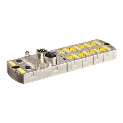
Murrelektronik IMPACT67 Series User manual

MANUAL ENGLISH
for devices of the IMPACT67 series
Art.-No. 55150 | 55151 | 55152 | 55170 | 55171 | 55172
© Murrelektronik GmbH

Murrelektronik GmbH
Falkenstraße 3
71570 Oppenweiler
GERMANY
Phone +49 7191 47-0
Fax +49 7191 47-491000
NOTE
Translation of the original instructions
This document is valid for the following products:
Document status:
Name Art.-No.
Impact67 DIO16 M12L 4P 55150
Impact67 DIO14 DIO2/IOL2 M12L 4P 55151
Impact67 DIO12 DIO4/IOL4 M12L 4P 55152
Impact67 PN DIO16 M12L 5P 55170
Impact67 PN DIO14 DIO2/IOL2 M12L 5P 55171
Impact67 PN DIO12 DIO4/IOL4 M12L 5P 55172
Manual number 55170
Language EN
Version 1.3
Date 2020-02

MANUAL ENGLISH
for devices of the IMPACT67 series Art.-No. 55150 | 55151 | 55152 | 55170 | 55171 | 55172
3 / 145
Table of Contents
1 Introduction 6
1.1 Service and support 6
1.1.1 About this manual 7
1.1.2 Symbols 8
1.1.3 Trademarks 9
2 For your safety 10
2.1 General safety instructions 10
2.2 Intended purpose 11
2.3 Environmentally friendly disposal 11
3 Description 13
3.1 Product Designation Code 13
3.2 PROFINET IO 13
3.2.1 PROFINET IO Communication 13
3.2.2 Structure of the conformance classes 14
3.2.3 PROFIenergy 15
3.2.4 Shared Device 16
3.3 PROFINET IRT 17
3.4 Media redundancy 18
3.5 IO-Link 20
3.5.1 Data storage mode 21
3.6 Module 22
3.6.1 Module structure 22
3.6.2 Display elements 24
3.6.3 Connections 25
3.6.3.1 Pin assignment 25
3.6.4 DIP switch settings 27
4 Technical Data 28
4.1 Electrical data 28
4.2 Environmental characteristics 30
4.3 Protection 31
4.4 Mechanical data 31
4.5 Product reliability 31
4.6 Conformity, Approvals 32
5 Mounting 33
5.1 Requirements 33
5.2 Dimensions 33
5.3 Mounting distance 34
5.4 Installing the module 35
5.4.1 Functional ground 37
5.4.2 Addressing lid 38

MANUAL ENGLISH
for devices of the IMPACT67 series Art.-No. 55150 | 55151 | 55152 | 55170 | 55171 | 55172
4 / 145
6 Installation 39
6.1 Electrical Installation of the Module 39
6.1.1 Sensors and actuators 40
6.1.2 Connecting the Ethernet bus 42
6.1.3 Power supply connection 43
6.2 Ensuring Tightness (IP67) 44
7 Start-up 45
7.1 Loading GSDML Files 45
8 Configuration/settings 48
8.1 Module configuration 48
8.2 Module parameterization 56
8.2.1 Module parameters 56
8.2.2 Diagnostic parameters 58
8.2.3 Tool parameters 65
8.2.4 General parameters 66
8.2.5 Description of the parameters of the IO-Link ports 72
8.3 IO-Link configuration 83
8.4 Cyclic and acyclic communication 85
8.4.1 Acyclic IO-Link access 86
8.4.2 I&M data 87
8.4.3 IO-Link function block 90
8.5 Basic setting 94
8.6 Project planning of the Fast Start Up 103
8.7 Media redundancy (MRP) configuration 105
8.8 Isochronous real time (IRT) configuration 110
8.9 Shared Device configuration 113
8.10 SNMP 117
8.11 PROFIenergy configuration 117
9 Operation 118
9.1 Diagnostic 118
9.1.1 LED indications 118
9.1.2 Extended LED indications 123
9.2 PROFINET Diagnostics 127
9.2.1 General diagnostic messages 128
9.2.2 General diagnostic messages at IO-Link ports 128
9.2.3 Diagnostic messages at IO-Link ports 129
9.2.3.1 According to IO-Link integration guideline Edition 1 129
9.2.3.2 Murrelektronik IO-Link - Integration and extended integra-
tion 131
9.3 Maintenance and cleaning 140

Introduction
User manual 55170_hdb_en_13 6 / 145
1 Introduction
1.1 Service and support
Service and support
Sales Our sales staff in-house and in the field, and our technicians will support you
at all times.
CONNECTIVITY-
System advisors
Our system advisors are your competent contact persons if you want to devel-
op CONNECTIVITY solutions. They cooperate with you to find the best solu-
tions for your electrical installations.
Our CONNECTIVITY system advisors find ways that help you to permanently
improve the competitiveness of your machines and plants.
Customer Service Cen-
ter (CSC)
Our staff of the Customer Service Center will help you with all questions con-
cerning installation and start-up. They support you, for example, if you have
problems with combining hardware and software products from different man-
ufacturers.
A number of support tools and measurement facilities are available for field
bus systems and EMC interference.
Call us on +49 7191 47-2050 or send us an
e-mail to: support@murrelektronik.com
Service addresses Murrelektronik GmbH has a policy of customer proximity, both at the national
and international level. Please visit our website to find your contact person:
www.murrelektronik.com

Introduction
User manual 55170_hdb_en_13 7 / 145
1.1.1 About this manual
Scope This document describes the use of the devices
Information This document contains information on
fitting and electrical installation
startup and parameterization
circuit examples
fault diagnosis and troubleshooting
conformity and approval
Read this chapter carefully before you start working with the documenta-
tion or the device.
Read the documentation carefully before starting up the device.
Store the manual in a place that is accessible to all users at all times for
the entire service life of the device.
You will need general knowledge about automation engineering in order to un-
derstand this manual. In addition, planning and using automation systems re-
quires technical knowledge which is not contained in this manual.
Software
Purpose of this
document
This document instructs the technical staff of the machine manufacturer or
machine operator on the safe use of the devices described in the
"Scope of Application".
It does not include instructions on the safe use of the machine in which the
devices are integrated. For information about this, refer to the operating man-
ual of the machine.
Further applicable
documents
Name Art.-No.
Impact67 DIO16 M12L 4P 55150
Impact67 DIO14 DIO2/IOL2 M12L 4P 55151
Impact67 DIO12 DIO4/IOL4 M12L 4P 55152
Impact67 PN DIO16 M12L 5P 55170
Impact67 PN DIO14 DIO2/IOL2 M12L 5P 55171
Impact67 PN DIO12 DIO4/IOL4 M12L 5P 55172
Software used
Totally Integrated Automation (TIA) Portal V15 by Siemens AG
Murrelektronik IO-Link Device Tool 4.0.30
Document Art.-No. Location
Operating instructions 55150
55151
55152
55170
55171
55172
Included in the scope of delivery or down-
loadable from
http://shop.murrelektronik.com
Bus manual www.profibus.com

Introduction
User manual 55170_hdb_en_13 8 / 145
1.1.2 Symbols
This document includes information and notes that have to be observed for
your own safety and to avoid injuries and material damage. They are marked
as follows:
DANGER!
Immediate danger
Failure to observe this warning involves an imminent risk of death or seri-
ous injuries.
WARNING!
Possible danger
Failure to observe this warning can lead to death or serious injuries.
CAUTION!
Low-risk danger
Failure to observe this warning can lead to mild to moderate injuries.
NOTICE
Possible material damage
Failure to observe the warning may cause damage to the device and/or
the system.
NOTE
Other technical information and notes of Murrelektronik GmbH.
RECOMMENDATION
Notes with this symbol are recommendations of Murrelektronik GmbH.
PRODUCTS AND ACCESSORIES
This symbol indicates accessories or product recommendations.
Instruction for use An arrow marks instructions.
Read and observe the instructions.
1 | If they are numbered, it is absolutely necessary to follow them in the cor-
rect order.
2 | Read and observe the instructions.
PROFINET
PROFIenergy
www.profibus.com
IO-Link http://www.io-link.com
Document Art.-No. Location

Introduction
User manual 55170_hdb_en_13 9 / 145
1.1.3 Trademarks
Trademarks of the following companies and institutions are used in this docu-
mentation:
PROFINET/PROFINET IO PROFIBUS Nutzerorganisation e.V. (PNO)
IO-Link c/o PROFIBUS Nutzerorganisation e.V. (PNO)

For your safety
User manual 55170_hdb_en_13 10 / 145
2 For your safety
Read this chapter carefully.
Only after that you may work with the fieldbus module.
2.1 General safety instructions
DANGER!
High electrical voltage in the machine/system.
Death or severe injuries resulting from electric shock.
When working on the machine/modules, comply with the five safety rules
of electrical engineering.
Protection of persons
and material property.
In accordance with DIN VDE 0105-100 – Operation of electrical installa-
tions; Part 100: General specifications
The five safety rules Protect against high electrical voltage
1 | Disconnect
2 | Secure against switching on again
3 | Make sure that there is no voltage on all poles.
4 | Ground and short-circuit
5 | Cover or
block off neighboring parts that are live or energized
Qualified personnel Only qualified personnel instructed in safety is allowed to install the module
and to put it into operation.
They are qualified if they meet the following requirements:
They have undergone suitable electrical engineering training,
They were trained by the machine operator to operate the machine and
instructed on the related safety regulations,
They have access to the Operating Instructions and the manual
They are familiar with the safety standards which are common practice in
automation engineering
They are familiar with the basic and technical standards related to the spe-
cific application
Use of the device Comply with all safety and accident prevention regulations when conduct-
ing project engineering, installation, commissioning, operation, and testing
of the device.
Check material resistance if aggressive media are used.
NOTE
Work on the hardware and software of the device may only be performed by
qualified personnel of Murrelektronik GmbH, with the exception of firmware
updates.

For your safety
User manual 55170_hdb_en_13 11 / 145
NOTE
Use only a power supply unit that allows max. 60 V DC or 25 V AC in case of
error. The power supply must comply with SELV or PELV.
Protective measures by
the
machine operator
Pay absolute attention to the instructions in this manual.
Pay attention to the test regulations contained in the operating instructions
of all connected components.
2.2 Intended purpose
Intended use IMPACT67 is a decentralized fieldbus module. It can be used in harsh indus-
trial environments up to degree of protection IP67.
Operation of the device in accordance with its designated use and the degree
of protection IP67 are only guaranteed if open male and female connectors
are closed using screw plugs.
Designated use also includes EMC-compliant electrical installation. The de-
vice is designated for use in industrial environment. Radio interference may
occur if used in a domestic or mixed environment.
If the fieldbus module is used in domestic and mixed environments, the
applicable standards must be observed.
Foreseeable misuse Do not alter the design, engineering, or electrical features of the module.
Do not use the module outside the application fields described in this
manual, the Technical Data or in the operating instructions.
Do not use the module as safety-related device. It does not meet the rel-
evant standards. Safety functions of the system are not ensured!
Do not use the Off state of the module outputs for safety-related require-
ments of the system/machine!
Do not use the module outdoors or for continuous operation in liquids.
Do not clean the module with a high-pressure cleaner.
Do not use the module as a climbing aid.
Warranty and liability
claims
Warranty and liability claims shall be lost if
the product is not used according to its designated use,
damage is caused because the manual and the operating instructions
have not been observed,
the personnel was/is not qualified.
2.3 Environmentally friendly disposal
Comply with
country-specific
waste disposal regula-
tions.
Always dispose of scrap devices in compliance with the valid
country-specific regulations for waste disposal
(e.g., the European Waste Code 16 02 14).
Only qualified persons
may sort scrap materi-
als.
Proceed with caution when dismantling the device since you could injure
yourself.
Sort the separated components into the correct recycling line.

For your safety
User manual 55170_hdb_en_13 12 / 145
Disposal
The product can be returned to Murrelektronik GmbH free of charge for dis-
posal. The same is true for the original packaging and any batteries or power
packs. Any units that have been contaminated with hazardous substances will
not be accepted for repair or disposal.
Returns
Label the product and the packaging with
"For disposal".
Package the product.
Send the package to:
Murrelektronik GmbH
Falkenstraße 3
71570 Oppenweiler | GERMANY
We will make sure that the items are disposed of in accordance with German
legislation. The most recent owner is responsible for transport to the return
point until items arrive at their destination.

Description
User manual 55170_hdb_en_13 13 / 145
3 Description
3.1 Product Designation Code
Product designation
format
The designation is based on a scheme that indicates the product’s function.
3.2 PROFINET IO
3.2.1 PROFINET IO Communication
IEC 61784-2 PROFINET IO is an open communication protocol that complies with IEC
61784-2. The communication protocol is based on Ethernet.
Data exchange Data is exchanged between the control unit, referred to as the PROFINET IO
controller, and connected users which are called PROFINET IO devices.
Communication Communication is based on a full-duplex Ethernet network running at
100 Mbit/s. IO controllers and IO devices communicate by means of Ethernet
telegrams. Devices exchange data cyclically based on the provider-consumer
principle. Devices function as receiver (consumer) and transmitter (provider)
at the same time.
The IO controller sends output data to the IO devices and receives input data
from the IO devices. The IO devices send input data and receive output data.
Other components of the communication protocol include telegrams in form of
acyclic communication for parameter transfer and read/write access to the
I&M data or manufacturer-specific features.
Impact67 PN DIO16 M12L 5P
Impact67 Productfamily
PN
PROFINET
DIO16
16 digital in- and outputs (DIO)
DIO14 DIO2/IOL2
14 digital in- and outputs (DIO)
2 IOL Class B
DIO12 DIO4/IOL4
12 digital in- and outputs (DIO)
4 IOL Class B
Number of channels
M12L Coding
4P
5P
4-pole
5-pole

Description
User manual 55170_hdb_en_13 14 / 145
3.2.2 Structure of the conformance classes
Structure The scope of functions of PROFINET IO is clearly classified in "Conformance
Classes" (CC). These classes give a clear overview of the various minimum
properties. There are three conformance classes:
Fig. 3-1: Structure of the conformance classes
CC-A CC-A offers basic functions for PROFINET IO with RT communication. Typical
cycle time starting from 2 ms. In this case, unmanaged switches can also be
used. Wireless communication is possible only in this class. All IMPACT67
conform to class CC-A.
The TREE unmanaged switches by MURRELEKTRONIK can be used as
switches.
CC-B CC-B expands the concept by the inclusion of network diagnostics and topol-
ogy information. Cycle time typically from 2 ms. The topology information and
projected device names enable easy device exchange. The defective device
can be easily exchanged for a new device with factory settings. All IMPACT67
conform to class CC-B.
CC-C CC-C describes the basic functions for devices with hardware-supported
bandwidth reservation and synchronization (RT communication) and therefore
forms the basis for isochronous applications. The implementation of Isochro-
nous Real Time (IRT) in Ethernet controllers makes it possible to reach update
times of 31.25μs and a jitter accuracy of less than 1μs.

Description
User manual 55170_hdb_en_13 15 / 145
3.2.3 PROFIenergy
Fig. 3-2: PROFIenergy Power consumption
PROFIenergy is an additional profile for PROFINET.
It represents a standardized way of achieving and managing energy savings
in production networks.
Using special commands, scheduled saving functions can be performed via
PROFIenergy. These are implemented in the devices and require no addition-
al hard-wired systems.
The module supports the PROFIenergy standard version and provides a large
number of commands.
For further information, refer to chap. 8.11 "PROFIenergy configuration"

Description
User manual 55170_hdb_en_13 16 / 145
3.2.4 Shared Device
Shared Device is a PROFINET IO function which enables access to an IO de-
vice from two IO controllers. A special advantage is the use of Shared Device
in systems with standard and failsafe control units.
The module gives the second standard IO controller read access to the input
and output data. This data is summarized in a subslot.
Fig. 3-3: Module in Shared Device
For further information, refer to chap. 8.9 "Shared Device configuration"

Description
User manual 55170_hdb_en_13 17 / 145
3.3 PROFINET IRT
Isochronous Real Time
(IRT)
For PROFINET, an isochronous data exchange by the transmission of data
packages in regular time intervals of a few hundred milliseconds up to four mil-
liseconds is defined by the IRT (Isochronous Real Time) concept.
The beginning of a bus cycle is adhered to with the highest precision (jitter ≤1
µs). Each of the individual time intervals during the IRT communication is split
into an IRT interval and an open standard interval which requires the use of
special IRT switches.
For further information, refer to chap. 8.8 "Isochronous real time (IRT) config-
uration"
Communication cycle
with IRT and RT
Fig. 3-4: Division of communication cycle into IRT and RT

Description
User manual 55170_hdb_en_13 18 / 145
3.4 Media redundancy
Media redundancy
(MRP)
The Media Redundancy Protocol (MRP) according to IEC 62439 describes
the PROFINET redundancy with a typical reconfiguration time of <200 ms for
the communication lines with TCP / IP and RT frames after an error. The fault-
free operation of an automation system implies a Media Redundancy Manag-
er (MRM) and several Media Redundancy Clients (MRC) arranged in a ring.
Fig. 3-5: Normal operation

Description
User manual 55170_hdb_en_13 19 / 145
Fig. 3-6: Malfunction
Function of a Media
Redundancy Manager
(MRM)
The function of a Media Redundancy Manager (MRM) is to check the opera-
bility of the ring structure specified by the configuration.
This is done by sending cyclic test telegrams. As long as the test telegrams
are received again by the MRM, the ring structure is intact.
An MRM uses this behavior to prevent circulation of telegrams and to convert
a ring structure into a line structure.
A Media Redundancy Client (MRC) is a switch that functions only as a so-
called "forwarder" of telegrams and does normally not play an active role.
MRC must have two switch ports in order to connect to other MRCs or the
MRM in a single ring. The modules can be configured as MRCs.
When interrupted from the ring, Profinet communication will continue after re-
configuration.
For further information, refer to chap. 8.7 "Media redundancy (MRP) configu-
ration"

Description
User manual 55170_hdb_en_13 20 / 145
3.5 IO-Link
IO-Link is a standardized link that enables connection of intelligent devices of
the sensor and actuator level to an automation system.
Communication takes place between a master and a device. A master module
has one or more ports. One device can be connected per port, which means
that the IO-Link is a point-to-point communication system and not a fieldbus.
The IO-Link master module builds the interface between the higher fieldbus
level and the IO-Link system.
The IO-Link device converts the data of the sensors/actuators into the IO-Link
format and passes the data on to the master. The device can be implemented
either directly into the sensor/actuator or as separate device.
Fig. 3-7: IO-Link
For further information, refer to chap. 8.3 "IO-Link configuration"
This manual suits for next models
10
Table of contents
Other Murrelektronik Control Unit manuals
Murrelektronik
Murrelektronik MVK-MP User manual

Murrelektronik
Murrelektronik Cube67 Series User manual

Murrelektronik
Murrelektronik MVK-MPNIO Series User manual

Murrelektronik
Murrelektronik IMPACT67-P User manual

Murrelektronik
Murrelektronik Data Panel xtreme DB DP-34044-1 User manual

Murrelektronik
Murrelektronik CUBE20S User manual
Murrelektronik
Murrelektronik Data Panel xtreme DB DP-34044-2 User manual