manuals.online logo
Brands
  1. Home
  2. •
  3. Brands
  4. •
  5. MuxLab
  6. •
  7. Extender
  8. •
  9. MuxLab 500754 User manual

MuxLab 500754 User manual

© MuxLab Inc. 94-000803-A SE-000803-B
8495 Dalton Road, Mount Royal, Quebec, Canada. H4T 1V5
Tel: (514) 905-0588 Fax: (514) 905-0589
Toll Free (North America): (877) 689-5228
E-mail: videoe[email protected] URL: www.muxlab.com
Specifications
Environment
HDMI 1.3a
Devices
DVDs, projectors, monitors, TVs, PCs, laptops, servers supporting HDMI.
Video Wall
NxM video wall capabilities.
Compatibility
Compatible with 500752, 500753 and 500811
Transmission
Transparent to the user.
Bandwidth
225 MHz
Signals
HDMI 1.3a protocol.
Connectors
One (1) HDMI receptacle.
One (1) RJ45S for Cat 5e/6 unshielded or shielded twisted pair.
One (1) 3.5mm jack for IR emitter/sensor.
One (1) DB9 Serial Port Connector.
Four (4) DIP switches for device ID addressing.
Note: HDMI, RS232 and Cat 5e/6 cables not included.
Maximum Distance
Based on a maximum length
of 6.6 ft (2 m) of HDMI cable
per end.
Cat5e/6: 330 ft (100 m) up to 1080P
Note: When installed in an electrically noisy environment, an STP cable must be
used. Also, cross-connections in the signal path reduce the effective distance
depending on the grade of twisted pair cable used.
Latency
One (1) Frame.
Compression
Motion JPEG
Bandwidth
60Mbps
Network Requirement
100BaseT for Point-to-Point; 1000BaseT for multi-point configurations.
IR Frequency
30 KHz to 60 KHz
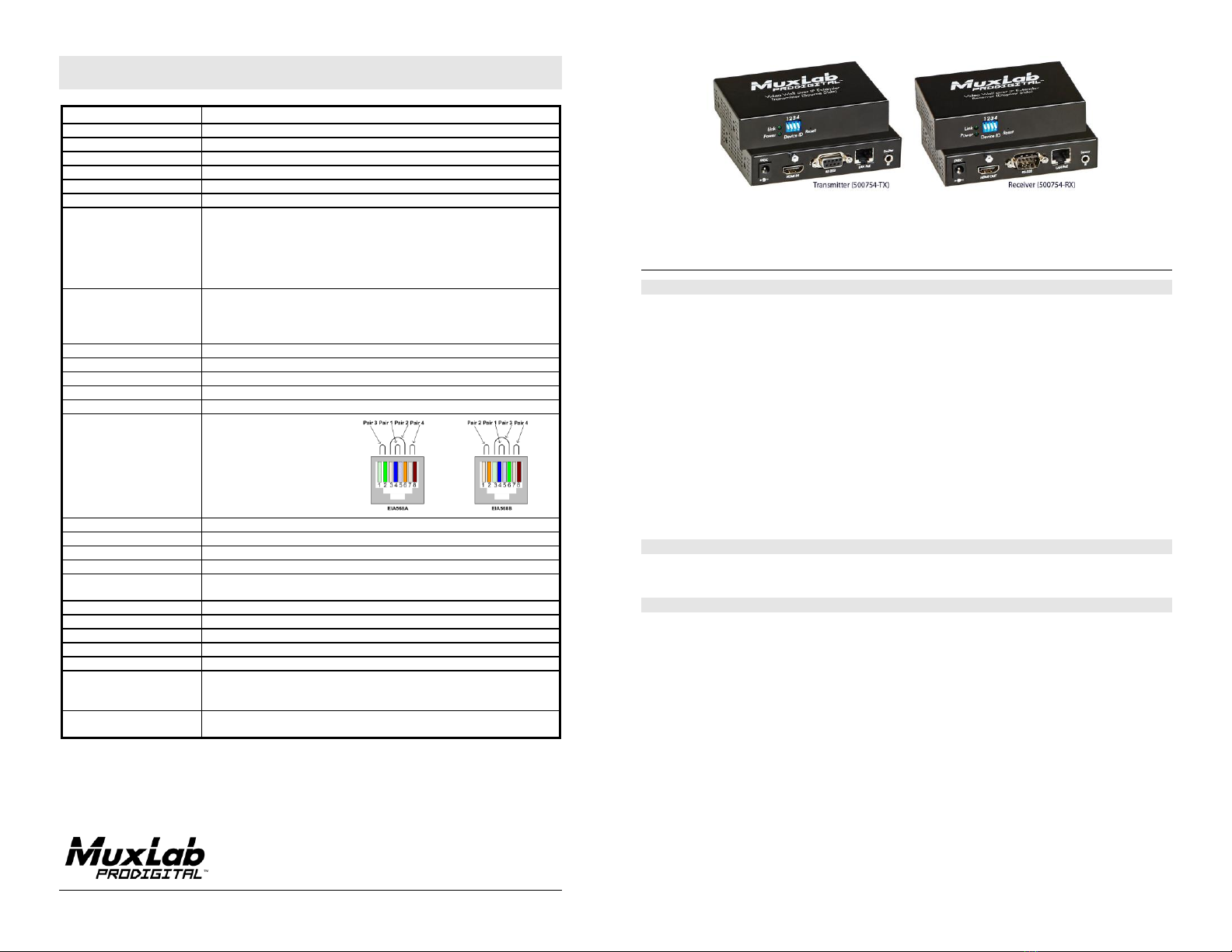
RJ45 Pin Configuration
Reverse Polarity Sensitive.
Use EIA/TIA 568A or 586B
straight-through wiring.
RJ45 Link
Pin 1 (R) Pin 2 (T)
Pin 3 (R) Pin 6 (T)
Pin 4 (R) Pin 5 (T)
Pin 7 (R) Pin 8 (T)
Cable
One (1) Cat 5e/6 or better twisted pair cable required.
Power Supply
Two (2) 110-240V/5VDC power supplies withinterchangeable blades.
PoE
IEEE 802.3af
Power Consumption
Transmitter: 2.9 Watt Receiver: 1.8 Watt
Temperature
Operating:0° to 40°C Storage: -20° to 85°C
Humidity:Up to 95% non-condensing
Enclosure
Metal
Dimensions
4.40” x 3.00” x 1.00” (11.2 x 7.6 x 2.5 cm)
Weight
1.1 lb (0.5 kg)
Compliance
Regulatory: FCC, CE, RoHS Flammability: 94V0
Warranty
2 years
Order Information
500754 Video Wall Over IP Extender Kit with PoE
500754-TX Video Wall Over IP Transmitter with PoE
500754-RX Video Wall Over IP Receiver with PoE
Accessories
500905 Rackmount Transceiver Chassis 3-Port
500906 Rackmount Transceiver Chassis 16-Port
500754 Video Wall over IP Extender Kit with PoE
Quick Installation Guide
Overview
The Video Wall over IP Extender Kit with PoE (500754) allows HDMI equipment to be connected up to
330 ft (100m) @ 1080p via one (1) Cat5e/6 unshielded twisted pair cable in a point-to-point
configuration. Point-to-multipoint, multipoint-to-multipoint, and Video Wall configurations are also
possible by connecting several Transmitters and Receivers to the same Ethernet local IP network via an
Ethernet Switch. The Transmitter (500754-TX) and Receiver (500754-RX) also support PoE (PD) if
used with a PoE Ethernet Switch. The kit comes with one (1) Transmitter and one (1) Receiver as well
as an IR Emitter and IR Sensor for remote control applications. Additional Transmitters and Receivers
may be purchased as kits or purchased separately depending on the intended application and number of
units required.
For the point-to-multipoint and multipoint-to-multipoint configuration the Ethernet Switch must have
Gigabit ports and DHCP Server capability and additionally support the IGMP communication protocol
for the multipoint-to-multipoint case. MuxLab recommends using the Cisco SG300 Series Managed
Switches.
The MuxLab ProDigital Network Controller (500811) is available to simplify the configuration and
utilization of the 500754 and other MuxLab IP based products via an Ethernet web interface.
Applications
Applications include commercial and residential AV systems, classroom projector systems, digital
signage, boardroom systems, collaborative PC systems, and medical information systems.
Installation
1. Identify the connectors on the Transmitter and Receiver as indicated on the product labels,
see the above front and rear product views for further details.
2. Verify that the distance between the HDMI Transmitter and Receiver is within MuxLab
specifications (see Specifications table for further details).
3. To install the Transmitter:
3a. Connect the Transmitter to the HDMI video source with an HDMI compliant cable.
3b. If the application is point-to-point, then connect one (1) length of Cat 5e/6 (or higher)
grade UTP cable to the RJ45 LINK connector on the Transmitter. If transmitting over
the network, use an Ethernet Switch between the TX & RX unit.
4. To install the Receiver:
4a. Connect the Receiver to the HDMI display equipment with an HDMI compliant cable.
4b. If the application is point-to-point, then connect one (1) Cat 5e/6 cable (or higher)
coming from the Transmitter, to the RJ45 LINK connector on the Receiver. If
transmitting over the network, use an Ethernet Switch between the TX & RX unit.
© MuxLab Inc. 2015
5. If the configuration is a point-to-multipoint or multipoint-to-multipoint:
5a. You will need to use an Ethernet Switch with Gigabit ports and DHCP Server support. In
addition IGMP Protocol support is required for the multipoint-to-multipoint case. Verify that
the Ethernet Switch is configured correctly and that the DHCP Server is enabled and
that the IGMP Protocol is enabled for multipoint-to-multipoint applications. See the
operating manual for more information about configuring the Ethernet Switch.
5b. Connect all Transmitters and Receivers to the Ethernet Switch.
5c. Use the DIP Switches to select a unique Device ID for each Transmitter present on the
network and configure each Receiver Device ID to the corresponding selected Transmitter.
Note: This step is not necessary if the MuxLab ProDigital Network Controller (500811) is used.
6. Powering the Transmitter or Receiver via an external power supply is only necessary where PoE
(PSE) is unavailable. If PoE is unavailable, connect the 5 VDC power supply to each Receiver and
to an AC power outlet. Next connect each Transmitter in the same manner. If power is present, the
green power LED on each Transmitter and Receiver will illuminate.
Note: Power ‘ON’ the Video Wall over IP Extender only after all data connections are made.
7. Power ‘ON’ the HDMI equipment and verify the image quality.
8. This product supports IR pass-thru control. If infrared remote control is needed to control the
Source equipment from the Display, connect the IR Sensor to the 3.5mm Stereo Jack of the
Receiver and the IR Emitter to the 3.5mm Mono Jack of the Transmitter.
Note: You can differentiate the IR Sensor and the IR Emitter by looking at the 3.5 mm plug.
The IR Sensor is using a Stereo Plug (3 Contacts) and the IR Emitter a mono plug (2
Contacts).
9. Position the IR Sensor so that it is directed at the hand-held remote control. For a clear IR signal
reception, aim the hand-held remote control at the top of the IR Sensor enclosure.
10. Position the IR Emitter as close as possible to the source’s IR Sensor (i.e. DVD player). For a clear
IR signal reception, the IR Emitter can be glued on the source’s IR Sensor. The IR Emitter’s signal
is transmitted from the side of the enclosure.
11. This product supports RS232 bidirectional communication. On the Transmitter, the RS232 port is
configured as a DCE; and on the Receiver as a DTE. Please connect your RS232 cable accordingly
as previously indicated. The default settings are 9600, N, 8, 1.
12. To send an RS232 packet to a specific device, you need to put the IP address in front of the packet.
This communication is meant to be machine to machine; and hexadecimal codes must be used. For
example, to send the message “Hello” to a device having an IP address of 192.168.168.55, send the
following hexadecimal string: 0xC0 0xA8 0xA8 0x37 0x48 0x65 0x6c 0x6c 0x6f. (or “192 168 168
55 H e l l o” in hexadecimal).
13. To setup a video wall, please use the 500811 ProDigital Network Controller and follow
the steps in the controller manual.
14. The following diagram illustrates a typical 2x2 Video Wall configuration.
Troubleshooting
The following table describes some of the symptoms, probable causes and possible solutions in regard to
the installation of the Video Wall over IP Extender Kit with PoE:
Symptom
Transmitter
LEDs
Receiver LEDs
Probable
Cause
Possible
Solutions
Power
Link
Power
Link
No image
OFF
OFF
OFF
OFF
No power
•Check power connections.
•Check PoE Ethernet
Switch setup.
No image
ON
OFF
ON
ON
Internal error
•Reboot the Transmitter.
No image
ON
ON
ON
OFF
Internal error
•Reboot the Receiver.
No image
ON
ON
ON
ON
UTP cable
•Check the Transmitter
UTP cable.
No image
ON
BLINK
ON
ON
UTP cable
•Check the Receiver UTP
cable.
No image
ON
BLINK
ON
BLINK
HDMI cable
•Check the HDMI cable
quality.
Choppy image
ON
BLINK
ON
BLINK
Ethernet Switch
•For multipoint-to-
multipoint enable the
IGMP mode on the
Gigabit Ethernet Switch.
Choppy sound
ON
BLINK
ON
BLINK
Synchronization
•Check cable length.
•Check the HDMI cable
quality.
Image flickers
when powering
up nearby
equipment.
ON
BLINK
ON
BLINK
Interference
•Use STP cables.
IR not
functioning
ON
BLINK
ON
BLINK
Remote control not
directed to the IR
Sensor or IR
Emitter not directed
to the source.
•Make sure the IR Sensor
is directed towards the
remote and the IR Emitter
to the equipment.
IR not
functioning
ON
BLINK
ON
BLINK
Interference from
sunlight,
fluorescent, neon or
halogen lights.
•Place the IR equipment
away from the interfering
light source.
IR not
functioning
ON
BLINK
ON
BLINK
RF radiation
interference from
the TV.
•Place the IR equipment
away from the interfering
RF radiation source.
If you still cannot diagnose the problem, please call MuxLab Customer Technical Support at:
877-689-5228 (toll-free in North America) or
(+1) 514-905-0588 (International).
RS232
RS232
HDMI
HDMI
HDMI
RS232
RS232
RS232
CATx
CATx
CATx
CATx
HDMI
HDMI
HDMI
CATx
CATx
DVD Player
500754-RX
VideoWall over IP Decoders
Media Player
CATx
HDMI
500754-TX
VideoWall over IP Encoder
500754-RX
VideoWall over IP Decoder
Source #1
Source #N
500754-RX
VideoWall over IP Decoders
PoE LAN Switch
2x2 Video Wall Display
Display #M
500754-TX
VideoWall over IP Encoder
500811
Network Controller
IR
IR
IR

Other MuxLab Extender manuals

MuxLab 500710 User manual

MuxLab

MuxLab 500710 User manual

MuxLab 500456 User manual

MuxLab

MuxLab 500456 User manual

MuxLab 500752 User manual

MuxLab

MuxLab 500752 User manual

MuxLab 500409 User manual

MuxLab

MuxLab 500409 User manual

MuxLab 500453 User manual

MuxLab

MuxLab 500453 User manual

MuxLab 500753 User manual

MuxLab

MuxLab 500753 User manual

MuxLab ProDigital 500485 User manual

MuxLab

MuxLab ProDigital 500485 User manual

MuxLab 500752 User manual

MuxLab

MuxLab 500752 User manual

MuxLab 500770 User manual

MuxLab

MuxLab 500770 User manual

MuxLab 500459-100 User manual

MuxLab

MuxLab 500459-100 User manual

MuxLab 500390 User manual

MuxLab

MuxLab 500390 User manual

MuxLab 500409 User manual

MuxLab

MuxLab 500409 User manual

MuxLab 500758 User manual

MuxLab

MuxLab 500758 User manual

MuxLab 500730 User manual

MuxLab

MuxLab 500730 User manual

MuxLab VGA Balun II User manual

MuxLab

MuxLab VGA Balun II User manual

MuxLab VideoEase MonoPro XLR User guide

MuxLab

MuxLab VideoEase MonoPro XLR User guide

MuxLab 500464 User manual

MuxLab

MuxLab 500464 User manual

MuxLab 500754 User manual

MuxLab

MuxLab 500754 User manual

MuxLab 500759-TX-HLO User manual

MuxLab

MuxLab 500759-TX-HLO User manual

MuxLab 500405 User manual

MuxLab

MuxLab 500405 User manual

MuxLab Broadcast 500734 User manual

MuxLab

MuxLab Broadcast 500734 User manual

MuxLab 500402 User manual

MuxLab

MuxLab 500402 User manual

MuxLab 500850 User manual

MuxLab

MuxLab 500850 User manual

MuxLab 500753 User manual

MuxLab

MuxLab 500753 User manual

Popular Extender manuals by other brands

Xiaomi MI R03 user manual

Xiaomi

Xiaomi MI R03 user manual

Avenview HDM3D-C5SP-4 user guide

Avenview

Avenview HDM3D-C5SP-4 user guide

TP-Link TL-WPA4220 TKIT Quick installation guide

TP-Link

TP-Link TL-WPA4220 TKIT Quick installation guide

StarTech.com ST12MHDLNV user manual

StarTech.com

StarTech.com ST12MHDLNV user manual

Wi-Ex SOHO YX545 overview

Wi-Ex

Wi-Ex SOHO YX545 overview

Lindy 38170 user manual

Lindy

Lindy 38170 user manual

National Instruments PXIe-5696 Getting started guide

National Instruments

National Instruments PXIe-5696 Getting started guide

Wilson Electronics AG Pro Quint 461104 installation guide

Wilson Electronics

Wilson Electronics AG Pro Quint 461104 installation guide

Gefen USB 2.0 LR Extender EXT-USB2.0-LR user manual

Gefen

Gefen USB 2.0 LR Extender EXT-USB2.0-LR user manual

Aztech WL556E Speci?cations

Aztech

Aztech WL556E Speci?cations

PROLiNK PEN1201 Quick installation guide

PROLiNK

PROLiNK PEN1201 Quick installation guide

Icron USB 2.0 RG2301 user guide

Icron

Icron USB 2.0 RG2301 user guide

SureCall Fusion2Go 2.0 Quick setup guide

SureCall

SureCall Fusion2Go 2.0 Quick setup guide

SLX SLx user guide

SLX

SLX SLx user guide

ATEN CE350 user manual

ATEN

ATEN CE350 user manual

Comfast CF-WR758AC user manual

Comfast

Comfast CF-WR758AC user manual

NTI XTENDEX ST-C6USBHE-HDBT Installation and operation manual

NTI

NTI XTENDEX ST-C6USBHE-HDBT Installation and operation manual

DDMALL HD-F01-TX user manual

DDMALL

DDMALL HD-F01-TX user manual

manuals.online logo
manuals.online logoBrands
  • About & Mission
  • Contact us
  • Privacy Policy
  • Terms and Conditions

Copyright 2025 Manuals.Online. All Rights Reserved.