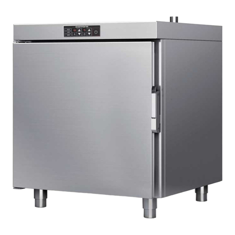
Mychef BAKERSHOP 3 460X330 Quick start guide

mychefcooking.com
PRODUCT MANUAL BAKERSHOP -DT.MP.BS.2103.2
1
BAKERSHOP
Product Manual
Installation, use and maintenance

mychefcooking.com
PRODUCT MANUAL BAKERSHOP -DT.MP.BS.2103.2
2
INDEX
1. INTRODUCTION...........................................................................................4
2. TECHNICAL CHARACTERISTICS ...................................................................5
2.1. Main characteristics Mychef Bakershop ............................................................. 5
3. GENERAL SAFETY AND ACCIDENT PREVENTION REGULATIONS ....................6
3.1. Personnel responsible for using the equipment............................................... 6
3.2. Electrical hazard .................................................................................................... 6
3.3. Thermal hazard...................................................................................................... 6
3.4. Corrosion hazard .................................................................................................. 7
4. RECEPTION, TRANSPORT AND POSITIONING.............................................8
4.1. Reception............................................................................................................... 8
4.2. Transport................................................................................................................ 8
4.3. Positioning ............................................................................................................. 9
5. INSTALLATION...........................................................................................11
5.1. Electrical connection .......................................................................................... 11
5.1.1.Three-phase connection 400V 3L+N ...................................................... 12
5.1.2.Three-phase connection 230V 3L............................................................ 12
5.1.3.Single-phase connection 230V L+N........................................................ 13
5.2. Water connection................................................................................................ 13
5.2.1.Water input................................................................................................. 13
5.2.2.Water connection kit to carafe ................................................................. 14
5.3. Vapour condensation hood............................................................................... 14
6. USE.............................................................................................................15
6.1. Control Panel....................................................................................................... 15
6.1.1.Switching on the equipment .................................................................... 20
6.1.2.Cooking control ......................................................................................... 20
6.1.3.Start of the cooking cycle ......................................................................... 23
6.1.4.End of cycle ................................................................................................ 24
6.1.5.Speed selection ......................................................................................... 24
6.1.6.Saving a program ...................................................................................... 25
6.1.7.Retrieve a program.................................................................................... 25
6.1.8.Quick memories......................................................................................... 26
6.2. NightWatch.......................................................................................................... 26
6.3. Errors and alarms ................................................................................................ 27
mychefcooking.com
PRODUCT MANUAL BAKERSHOP -DT.MP.BS.2103.2
3
7. REMOTE CONTROL USE.............................................................................29
7.1. Remote control setup ......................................................................................... 29
7.1.1.Creating a new user .................................................................................. 29
7.1.2.Wi-Fi connectivity ...................................................................................... 30
7.1.3.Linking the oven to the device (mobile phone, tablet or computer) .. 32
7.1.4.Control panel ............................................................................................. 33
7.2. Google Home setup and voice assistant.......................................................... 36
7.2.1.Synchronizing oven to Google Home..................................................... 36
7.2.2.Voice commands for oven control........................................................... 39
7.2.3.Adding automated routines ..................................................................... 41
7.3. Support functions................................................................................................ 44
7.3.1.Reset Wi-Fi settings ................................................................................... 44
7.3.2.Show MAC address ................................................................................... 44
7.3.3.Unlink the "Mychef Control" service........................................................ 44
7.3.4.Desktop application for intelligent control............................................. 45
7.4. Table of states ..................................................................................................... 46
7.5. Recipes................................................................................................................. 46
8. MAINTENANCE ..........................................................................................47
8.1. Cleaning............................................................................................................... 47
8.1.1.Suction ........................................................................................................ 47
8.1.2.Door gasket................................................................................................ 48
8.1.3.Outer housing............................................................................................ 49
8.1.4.Control panel ............................................................................................. 49
8.1.5.Front water drain ....................................................................................... 49
8.1.6.Interior/exterior door compartment........................................................ 49
8.2. Preventive maintenance..................................................................................... 50

mychefcooking.com
PRODUCT MANUAL BAKERSHOP -DT.MP.BS.2103.2
4
1. INTRODUCTION
This manual has been carefully prepared and reviewed to provide reliable information and
assistance for proper installation, use, and maintenance that will ensure proper operation
and prolong the life of the oven. This manual is divided into three parts, the first part
dedicated to the installation of the equipment at the working point, and the second part
focused on the use and the third part in the cleaning and maintenance of the oven.
Before any intervention or use of the equipment, it is necessary to read this
manual carefully and completely.
The manufacturer declines all implicit or explicit responsibility for any errors or omissions it
may contain.
- The oven may not be used by personnel who have not received any kind of training,
and who do not have the necessary skills or experience for the proper functioning
of the equipment. Do not let children use or play with the equipment.
- The owner of the equipment is obliged to have this manual read by personnel
responsible for its use and maintenance and to keep this manual in a safe place for
use by all users of the equipment and for future reference. If the equipment is sold
to others, they must be given this manual.
- This oven must only be used for its intended purpose, i.e., cooking, heating,
regenerating or dehydrating food. Any other use can be dangerous and can result
in personal injury and property damage.
- The equipment is shipped from the factory once it has been calibrated and has
passed rigorous quality and safety tests that ensure its correct operation.
The manufacturer will disclaim any responsibility for problems caused by
improper installation, modification, use or maintenance.

mychefcooking.com
PRODUCT MANUAL BAKERSHOP -DT.MP.BS.2103.2
5
2. TECHNICAL CHARACTERISTICS
2.1. Main characteristics Mychef Bakershop
BAKERSHOP
3 460X330
BAKERSHOP
3 600X400
Exterior dimensions
(Width x Depth x
Height) (mm)
620x690x430
760x760x430
Capacity
3 460x330
3 600x400
BAKERSHOP
4 460X330
BAKERSHOP
4 600X400
BAKERSHOP
6 600X400
BAKERSHOP
10 600X400
Exterior dimensions
(Width x Depth x
Height) (mm)
620x690x522
760x760x522
760x760x646
760x760x946
Capacity
4 460x330
4 600x400
6 600x400
10 600x400
Table 1. Main characteristics of Mychef Bakershop ovens
The maximum recommended food load per 600x400 tray is 5 Kg. The maximum
recommended food load per 460x330 tray is 3.5 Kg.

mychefcooking.com
PRODUCT MANUAL BAKERSHOP -DT.MP.BS.2103.2
6
3. GENERAL SAFETY AND ACCIDENT PREVENTION REGULATIONS
3.1. Personnel responsible for using the equipment
The use of the equipment is reserved for trained personnel.
Personnel who perform any action on the oven, such as operation, cleaning,
installation, handling, etc., must be familiar with the safety regulations and
the Operating Instructions.
Do not allow unauthorized personnel to use, handle or clean the
equipment.
3.2. Electrical hazard
Work on the electrical supply side and access to live parts may only be carried out by
qualified personnel under their own responsibility. In any case, such access must be made
with the equipment disconnected from the power supply.
If the appliance is placed on a cart or on tables that have some mobility, do not allow it to
move while connected to the power supply to avoid possible damage to wiring, drainage
pipes or water inlets. If the equipment is to be moved or repositioned, the cables and the
drainage and water intake pipes must be disconnected.
3.3. Thermal hazard
When the equipment is in operation, the door should be opened slowly and carefully to
avoid possible burns from steam or hot air that may escape from inside the cooking
chamber.
Keep the ventilation openings free of obstacles. Do not install the
equipment in the vicinity of flammable products. Avoid positioning the
oven near heat sources such as stoves, grills, fryers, etc. Check the safety
distances in chapter Positioning.
DANGER OF ACCIDENT! Be careful when using food containers in the oven
when the top tray is 160 cm or more high. There is a risk of injury caused by
the hot contents of the trays.
While the oven is in operation, avoid touching metal parts and the door
glass as they may exceed 60°C. Touch only the handle and the control
panel.

mychefcooking.com
PRODUCT MANUAL BAKERSHOP -DT.MP.BS.2103.2
7
3.4. Corrosion hazard
When using cleaning products, special attention and appropriate safety measures should
be taken when handling these products. Always read the safety data sheet for the different
chemicals before use and follow the instructions for use. These products in contact with any
part of the body are abrasive and can cause skin and eye irritations and causticity.
During cleaning of the oven and in the event of aerosols or mist forming when handling
cleaning products, wear a mask with a P2 / P3 type particle filter, goggles for protection
against splashes and/or splashes and chemical protection gloves.
DA21 cleaning products have been specially formulated for the correct cleaning and
protection of Mychef ovens with automatic washing. The product contains, in addition to
detergent, polish for a perfect finish. The use of this detergent is mandatory in the Mychef
Bakershop ovens.
Use DA21 detergent in the Mychef Bakershop. The use of other products
will void the warranty.

mychefcooking.com
PRODUCT MANUAL BAKERSHOP -DT.MP.BS.2103.2
8
4. RECEPTION, TRANSPORT AND POSITIONING
Before carrying out the installation, the dimensions of the site where the equipment is to be
placed and the electrical and water connections must be verified and seen to be within the
parameters detailed in section 4.3 below.
4.1. Reception
Once the oven has been received, check that the model purchased corresponds to the
order.
Check that the packaging has not been damaged during transport and that no parts of the
equipment are missing. If you detect any anomaly or problem, contact your dealer
immediately.
4.2. Transport
The equipment should be transported in its original packaging to the closest location to the
point of installation to avoid damage as much as possible. It is recommended to keep the
original packaging until the equipment is properly installed and in operation.
To move the equipment and place it in your workspace, the following observations should
be taken into account:
-The measurements of the different models to pass through narrow places (corridors,
doors, narrow spaces). See chapter 2.
-The handling must be done with the necessary personnel to move the load of the
furniture taking into account the current occupational safety regulations at the place
of installation.
-The oven must always be in an upright position during transport. It must be lifted
perpendicularly to the ground and transported parallel to it.
-Make sure that during transport it does not tip over and is not hit by any object.
Be careful with the legs and the siphon when positioning the oven on the
final location.

mychefcooking.com
PRODUCT MANUAL BAKERSHOP -DT.MP.BS.2103.2
9
4.3. Positioning
-Place the oven at a comfortable distance from the wall so that the electrical and water
connections can be made. There must be a minimum clearance from the oven parts
to allow for proper ventilation and cooling. This minimum distance is:
o50mm on the left and right sides
o50mm from the rear
o500mm from the top
-The equipment should be placed on a Mychef support table or wall mount.
-If there are sources of heat or steam near the equipment (stove, grill, iron, deep fryer,
pasta cooker, kettle, tilting frying pan, etc.), these must be at a distance of more than
1 metre.
-Check that the oven is not exposed to hot air or vapours in the areas where the
cooling fans are located (front right and rear left).
Figure 1. Suction areas for cooling
-Once it is placed in the workspace, check that it is level.

mychefcooking.com
PRODUCT MANUAL BAKERSHOP -DT.MP.BS.2103.2
10
Figure 2. Example of a suitable location for installation
Be extremely careful with the cooling areas of the oven. If it sucks in vapours
or hot air it can drastically reduce the life span of the components.
For the installation of Mychef stacked ovens, follow the instructions supplied
with the corresponding stacking kit.
1000mm
50mm
500m
m
50mm
50mm

mychefcooking.com
PRODUCT MANUAL BAKERSHOP -DT.MP.BS.2103.2
11
5. INSTALLATION
5.1. Electrical connection
Check that the voltage reaching the point where the oven is to be switched on corresponds
to the operating voltage of the equipment.
The following table indicates the electrical characteristics of each oven:
Voltage
Power
(kW)
Rated current
(A)
Cross-section cable
(mm2)
3 460x330
230/L+N/50-60
3.6
11
1.5
3 600x400
230/L+N/50-60
3.6
20
2.5
4 460x330
230/L+N/50-60
3.6
30
4.0
4 600x400
400/3L+N/50-60
6.3
10
1.5
230/3L/50-60
6.3
17
2.5
230/3L+N/50-60
6.3
24
4.0
6 600x400
400/3L+N/50-60
9.3
14
1.5
230/3L/50-60
9.3
25
2.5
10 600x400
400/3L+N/50-60
15.6
24
2.5
230/3L/50-60
15.6
42
10.0
Table 2. Electrical connection characteristics
Before carrying out any electrical work, make sure that no electrical current is supplied at
the point of connection of the equipment.
The device must be connected to the mains via an all-pole switch with a contact opening
distance of more than 3mm. Also install a class A differential device and an overcurrent
protection.
Always ensure effective grounding.
Connect the equipment to an equipotential bonding system using the contact specially
provided for this purpose (see equipotential bonding sign on the bottom left of the
equipment). If two pieces of equipment are stacked, both must be connected to the
equipotentiality system.
The connection to an equipotential system guarantees additional safety in
case of simultaneous earth leakage and differential failure.
The wiring and other safety devices used for the electrical installation must have the
appropriate section for the equipment in question.

mychefcooking.com
PRODUCT MANUAL BAKERSHOP -DT.MP.BS.2103.2
12
In any case, respect the regulations in force for the connection of the
equipment to the low voltage network.
Before starting the electrical installation, check that the electrical requirements of the oven
and the power supply are the same.
Once the connection has been made, check that no cables are loose and that they are all
firmly attached. Also secure the cable gland.
Never connect a phase to neutral or ground. Check that the installation
voltages correspond to those of the equipment.
The following subchapters show the three possible types of connections for Mychef ovens.
The voltage of each oven can be found on its identification sticker.
5.1.1. Three-phase connection 400V 3L+N
Color
Cable
■
Brown
L1
■
Black
L2
■
Grey
L3
■
Blue
Neutral
■
Green-yellow
Grounding
Table 3. Three-phase cable 400V 3L+N
5.1.2. Three-phase connection 230V 3L
Color
Cable
■
Brown
L1
■
Black
L2
■
Grey
L3
■
Green-yellow
Grounding
Table 4. Three-phase cable 230V 3L

mychefcooking.com
PRODUCT MANUAL BAKERSHOP -DT.MP.BS.2103.2
13
5.1.3. Single-phase connection 230V L+N
Color
Cable
■
Brown
L1
■
Blue
Neutral
■
Green-yellow
Grounding
Table 5. Single-phase connection 230V L+N
5.2. Water connection
5.2.1. Water input
Cold water (max. 30°C) ¾ inch 150 to 400 kPa dynamic flow pressure.
Drinking quality water with the following characteristics:
- Hardness between 3º and 6º FH
- PH between 6.5 and 8.5
- Chlorides (Cl-) less than 30 mg/L
- Chlorine (Cl2) less than 0.2 mg/L
- Iron (Fe) less than 0.1 mg/L
- Manganese (Mn) less than 0.05 mg/L
- Copper (Cu) less than 0.05 mg/L
- Conductivity less than 20uS/cm
Use of descaler and Mychef filter mandatory.
The use of water with different characteristics than those indicated may
cause serious problems in the components of the oven, such as corrosion in
the cooking chamber or the glass, premature failure of the solenoid valves,
etc.
Periodically check the quality of the water of the oven.
The oven has a water inlet ¾’’ at the back of the oven for steam generation and for self-
cleaning processes.

mychefcooking.com
PRODUCT MANUAL BAKERSHOP -DT.MP.BS.2103.2
14
Figure 3. Water intake for Bakershop 3 and
Bakershop 4 (460x330)
Figure 4. Water intake for Bakershop
4,6,10 (600x400)
In the case of a new installation, the water must be left to run until the
connection is completely purified. This operation must be repeated each
time work or repairs are carried out on the water system that feeds the oven.
5.2.2. Water connection kit to carafe
Refer to the installation manual supplied with the water pump kit for installation.
The water pump kit is an optional extra. The pump can be installed once the
oven is installed.
5.3. Vapor condensation hood
Refer to the installation manual supplied with the fume hood for installation.
The vapor condensation hood is an optional extra. The hood can be installed
once the oven is installed.

mychefcooking.com
PRODUCT MANUAL BAKERSHOP -DT.MP.BS.2103.2
15
6. USE
6.1. Control Panel
The control panel of the Bakershop ovens has three cooking phases, it allows managing the
humidity, temperature, time and fan speed parameters, and saving programs. In addition,
it has eight quick access programs.
The figure below shows the control panel for the Mychef Bakershop ovens. It consists of a
central screen with displays, indicators, and buttons.
Figure 5. Control panel

mychefcooking.com
PRODUCT MANUAL BAKERSHOP -DT.MP.BS.2103.2
16
The functionality of each of them is explained below:
Figure 6. Control panel detail
A
C
E
C
B
D
F
G
B
I
L
M
N
O
Q
H
I
J
K
P

mychefcooking.com
PRODUCT MANUAL BAKERSHOP -DT.MP.BS.2103.2
17
Block
Function
Description
A
Phase 1 button
Button for selecting the first cooking phase.
B
Phase 1 indicator
Flashing, it indicates we are in phase 1. In fixed color, it
indicates that this phase is active.
C
Phase 2 button
Button for selecting the second cooking phase.
D
Phase 2 indicator
Flashing indicates we are in phase 2. In fixed color, it
indicates that this phase is active.
E
Phase 3 button
Button for selecting the third cooking phase.
F
Phase indicator 3
Flashing indicates we are in phase 3. In fixed color, it
indicates that this phase is active.
G
Display screen
Displays the selected parameter: humidity,
temperature, time, or fan speed.
H
Program button
Allows to save or retrieve a program.
I
Adjustment button -
Decreases the selected parameter: program, level,
humidity, temperature, time, or fan speed.
J
Adjustment button +
Increases the selected parameter: program, level,
humidity, temperature, time, or fan speed.
K
Level button
Allows to adjust the parameters of a fermenter from the
same control.
L
Moisture button
Moisture selection button.
M
Temperature button
Temperature selection button.
N
Time button
Time selection button
O
Fan speed button
Fan speed selection button
P
Quick memory button
block M1..M8
With a long press, it records the current parameters in a
specific memory.
With a short press, it executes the cooking in memory.
Q
START/STOP button
Oven on/off and start/stop button.
If the oven is on but not baking, slight pressure will start
the preheating.
If the oven is preheating, slight pressure will skip the
preheating.
If the oven is on and baking, slight pressure will cancel
the baking cycle.
Table 6. Control panel description

mychefcooking.com
PRODUCT MANUAL BAKERSHOP -DT.MP.BS.2103.2
18
The central display is a very important part when interacting with the oven, since it indicates
the value of each cooking parameter.
Figure 7. Central screen
The parameter display format is explained below:
Icon
Function
The moisture level is shown with an H in the first digit. The
humidity value is shown next.
The chamber temperature is shown with a T in the first digit. The
temperature value in degrees Celsius is shown next.
The cooking time is shown with the two central points. The two
digits on the left are the hours, and the two digits on the right
are the minutes.
Cooking can also be continuous. In this case, CONT appears on
the display. For continuous cooking, press the adjustment key -
until CONT appears in the display.
The fan speed is shown with an F in the first digit. If the
convection fan is on high speed, HI is displayed. Otherwise, if
the convection fan is at a low speed, LO appears.

mychefcooking.com
PRODUCT MANUAL BAKERSHOP -DT.MP.BS.2103.2
19
The program is shown with a P in the first digit, followed by the
program number.
The level is shown with “THIS” or “FER”.
Level 1 (THIS) accesses the oven parameters, and level 2 (FER)
accesses the proofer parameters (OPTIONAL).
This icon indicates that a cooking process has been completed.
The DOOR message appears when the door is opened during a
cooking process.
The PREHEAT message is displayed during the oven preheating
processes, alternatively with the current oven chamber
temperature.
The LOAD message indicates that the oven has reached preheat
temperature and the oven is ready to charge. By closing the
door, the cooking cycle will start.
In the case of an error, the first two digits of the display show ER,
followed by the error number. Refer to the chapter on errors for
more information.
It is possible to change the operating parameters of the oven. In
the parameter edit menu, the central display shows a P, followed
by the parameter number. The two digits on the right show the
value of the parameter. Refer to the chapter on the configuration
menu for more information.
Table 7. Description of messages on the central screen

mychefcooking.com
PRODUCT MANUAL BAKERSHOP -DT.MP.BS.2103.2
20
6.1.1. Switching on the equipment
The equipment is switched on or off by pressing the START/STOP button for two seconds.
In order to protect the oven from possible overheating, some protective
elements may work even when the oven is switched off. When the oven is
at a safe temperature it will automatically turn off.
If the equipment does not turn on, check the status of the safety thermostat and the service
switch, located at the rear of the equipment.
Figure 8. Safety thermostat (A) and service
switch (B) for Bakershop 3 and Bakershop 4
(460x330)
Figure 9. Safety thermostat (A) and
service switch (B) for Bakershop 4,6,10
(600x400)
6.1.2. Cooking control
Temperature and time-controlled cooking
In this mode the oven automatically brings the temperature in the chamber up to the value
selected by the user so that when the door is opened and the food loaded, the temperature
in the chamber will be the same as the one selected at the start of cooking. The oven
automatically calculates the air temperature in the chamber and decides whether to heat it
up to the value to be reached.
In the temperature and time control mode with temperature setting we choose a certain
temperature and time by adjusting with the +/- buttons after having pressed the
TEMPERATURE and TIME buttons respectively.
By pressing the START/STOP button, the oven will start to preheat the chamber and will stop
when it has reached a level determined by the oven according to the temperature
requested by the user. At this point the display will show "Pht" alternately with the
temperature of the chamber.
This manual suits for next models
5
Table of contents
Other Mychef Oven manuals

Mychef
Mychef iCOOK User manual

Mychef
Mychef S Series User manual

Mychef
Mychef CONCEPT User manual

Mychef
Mychef iBAKE User manual

Mychef
Mychef COMPACT EVOLUTION 6 GN 2/3 User manual

Mychef
Mychef EVOLINE User manual

Mychef
Mychef COOK UP 4 GN 1/1 User manual

Mychef
Mychef 6GN 2/3 User manual

Mychef
Mychef BAKERSHOP User manual

Mychef
Mychef iCOOK Operating manual