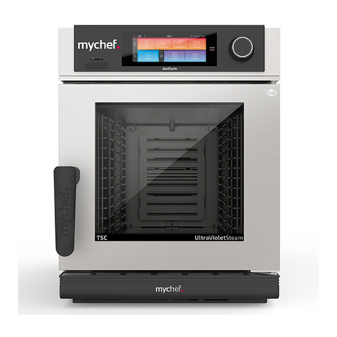
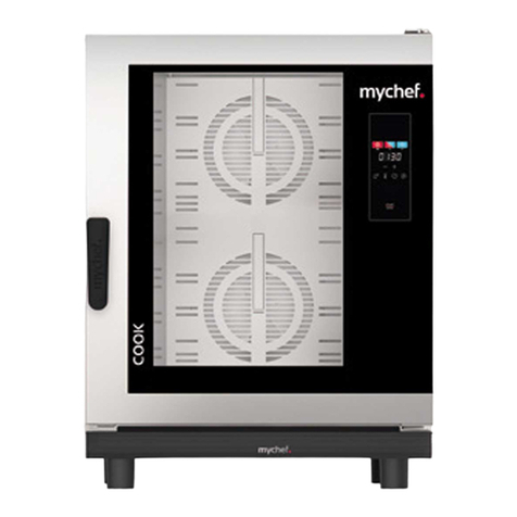
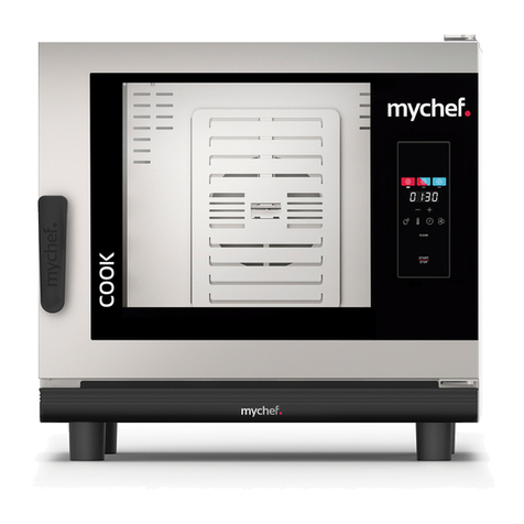
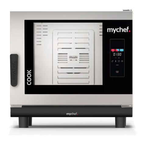
Mychef EVOLINE User manual

mychefcooking.com
PRODUCT MANUAL EVOLINE -DT.MP.EV.2103.2
1
EVOLINE
Product Manual
Installation, use and maintenance

210208_A
mychefcooking.com
2
PRODUCT MANUAL EVOLINE - DT.MP.EV.2103.2
INDEX
1. INTRODUCTION .............................................................................................3
2. TECHNICAL CHARACTERISTICS......................................................................4
2.1. Main characteristics ................................................................................................. 4
3. GENERAL SAFETY AND ACCIDENT PREVENTION REGULATIONS ..................7
3.1. Personnel responsible for using the equipment.................................................. 7
3.2. Electrical hazard ....................................................................................................... 7
3.3. Thermal hazard......................................................................................................... 7
4. RECEPTION, TRANSPORT AND POSITIONING ...............................................8
4.1. Reception.................................................................................................................. 8
4.2. Transport................................................................................................................... 8
4.3. Positioning ................................................................................................................ 9
5. INSTALLATION .............................................................................................10
5.1. Electrical connection ............................................................................................. 10
5.1.1. Evoline three-phase models ...................................................................... 10
5.1.2. Evoline single-phase models ..................................................................... 11
5.2. Water connection (appliances with humidity) .................................................... 12
5.2.1. Water input .................................................................................................. 12
5.2.2. Drain (appliances with humidity)............................................................... 12
6. USE...............................................................................................................13
6.1. Control panel.......................................................................................................... 13
6.2. Operation................................................................................................................ 14
6.2.1. Turning on the appliance ........................................................................... 14
6.2.2. Regeneration ............................................................................................... 14
6.2.3. End of cycle.................................................................................................. 14
6.2.4. Door open.................................................................................................... 15
6.2.5. Errors and faults........................................................................................... 15
7. MAINTENANCE ............................................................................................17
7.1. Cleaning.................................................................................................................. 17
7.1.1. Door gasket.................................................................................................. 18
7.1.2. Door opening .............................................................................................. 18
7.1.3. Owner liability.............................................................................................. 18
7.2. Preventive maintenance........................................................................................ 18
8. CE MARKING................................................................................................19
9. GENERAL ELECTRIC BLUEPRINT...................................................................20
210208_A
mychefcooking.com
3
PRODUCT MANUAL EVOLINE - DT.MP.EV.2103.2
1. INTRODUCTION
This document has been meticulously prepared for the purpose of providing reliable and
helpful information for proper installation, use, and maintenance to ensure correct
operation and prolonged life of the regenerator. This manual is divided in two sections. The
first section is dedicated to appliance installation in the workplace, and the second section
focuses on the operation and maintenance of the regenerator.
Before operating or using the appliance, read this manual carefully and
thoroughly.
The manufacturer declines all implicit or explicit responsibility for any errors or omissions it
may contain.
- The regenerator may not be used by personnel who have not received any kind of
training, and who do not have the necessary skills or experience for the proper
functioning of the equipment. Do not let children use or play with the equipment.
- The owner of the equipment is obliged to have this manual read by personnel
responsible for its use and maintenance and to keep this manual in a safe place for
use by all users of the equipment and for future reference. If the equipment is sold
to others, they must be given this manual.
- This regenerator must only be used for its intended purpose, i.e., cooking, heating,
regenerating or dehydrating food. Any other use can be dangerous and can result
in personal injury and property damage.
- The equipment is shipped from the factory once it has been calibrated and has
passed rigorous quality and safety tests that ensure its correct operation.
The manufacturer will disclaim any responsibility for problems caused by
improper installation, modification, use or maintenance.

210208_A
mychefcooking.com
4
PRODUCT MANUAL EVOLINE - DT.MP.EV.2103.2
2. TECHNICAL CHARACTERISTICS
2.1. Main characteristics
The main characteristics of the appliance are:
•Intuitive and easy-to-use panel with a touch keypad.
•Regeneration with or without humidity 140°C - 160°C.
•Temperature maintenance with or without humidity at 65°C.
•End of cycle control by time or by core probe.
•Digital indicators for humidity, steam, and time.
•Automatic pre-heating system.
•Automatic fan shutdown when opening the door.
•End of cycle audible and visual signal.
•Safety thermostat
•Open moisture drain.
•Humidity control from 0% to 99% (models with humidity).
•Hygienic cooking chamber with rounded corners.
•Built for a temperature range from 65ºC to 160°C.
•Easy-removal guides
•Water connection (models with humidity).
•Direct water injection (models with humidity).
•Made of stainless-steel.
•Adjustable legs to facilitate alignment and appliance stability.

210208_A
mychefcooking.com
5
PRODUCT MANUAL EVOLINE - DT.MP.EV.2103.2
Model
Without packaging
With packaging
Capacity
GN 1/1
Voltage
Power
(kW)
External
dimensions
(Width x Depth
x Height) (mm)
Weight
(kg)
Volume
(m3)
Weight
(kg)
F0460523
573x660x825
65
0.57
75
5*
230V, L+N;
50-60Hz
3.1
F0470523
FS470523
F0460511
743x661x825
75
0.7
85
5**
3.6
F0460512
743x723x825
80
0.7
90
5**
400V, 3L+N;
50-60 Hz
5.1
F0470512
FS470512
F0460611
773x729x890
118
1.23
125
6**
7.8
F0470611
FS470611
F0461011
773x729x1250
120
1.39
130
10**
10.5
F0471011
FS471011
Table 1. Dimensions and characteristics
*GN 2/3 TRAYS 65mm HEIGHT
**GN 1/1 TRAYS 65mm HEIGHT

210208_A
mychefcooking.com
6
PRODUCT MANUAL EVOLINE - DT.MP.EV.2103.2
The maximum recommended food load for 65 mm depth GN 1/1 trays is 5 kg, and for GN
5 2/3 trays it is 3.5 kg.
Table 2. Evoline models
Model
Capacity
Humidity
F0460523
5 2/3 GN trays
No
F0470523
Yes
FS470523
F0460511
5 1/1 GN trays
No
F0460512
5 1/1 GN trays
No
F0470512
Yes
FS470512
F0460611
6 1/1 GN trays
No
F0470611
Yes
FS470611
F0461011
10 1/1 GN trays
No
F0471011
Yes
FS471011

210208_A
mychefcooking.com
7
PRODUCT MANUAL EVOLINE - DT.MP.EV.2103.2
3. GENERAL SAFETY AND ACCIDENT PREVENTION REGULATIONS
3.1.Personnel responsible for using the equipment
The use of the equipment is reserved for trained personnel.
Personnel who perform any action on the regenerator, such as operation,
cleaning, installation, handling, etc., must be familiar with the safety
regulations and the operating instructions.
Do not allow unauthorized personnel to use, handle or clean the
equipment.
3.2. Electrical hazard
Work on the electrical supply side and access to electrical-live parts may only be carried out
by qualified personnel under their own responsibility. In any case, such access must be
made with the equipment disconnected from the power supply.
If the appliance is placed on a cart or on tables that have some mobility, do not allow it to
move while connected to the power supply to avoid possible damage to wiring, drainage
pipes or water inlets. If the equipment is to be moved or repositioned, the cables and the
drainage and water intake pipes must be disconnected.
3.3. Thermal hazard
When the equipment is in operation, the door should be opened slowly and carefully to
avoid possible burns from steam or hot air that may escape from inside the cooking
chamber.
Keep the ventilation openings free of obstacles. Do not install the
equipment in the vicinity of flammable products. Avoid positioning the
regenerator near heat sources such as stoves, grills, fryers, etc. Check the
safety distances in chapter Positioning.
DANGER OF ACCIDENT! Be careful when using food containers in the
regenerator when the top tray is 1.60 m or more high. There is a risk of
injury caused by the hot contents of the GN trays.
While the oven is in operation, avoid touching metal parts that may exceed
60°C. Touch only the handle and the control panel.

210208_A
mychefcooking.com
8
PRODUCT MANUAL EVOLINE - DT.MP.EV.2103.2
4. RECEPTION, TRANSPORT AND POSITIONING
Before carrying out the installation, the dimensions of the site where the equipment is to be
placed and the electrical and water connections must be verified and seen to be within the
parameters detailed in section 4.3 below.
4.1.Reception
Once the regenerator has been received, check that the model purchased corresponds to
the order.
Check that the packaging has not been damaged during transport and that no parts of the
equipment are missing. If you detect any anomaly or problem, contact your dealer
immediately.
4.2.Transport
The equipment should be transported in its original packaging to the closest location to the
point of installation to avoid damage as much as possible. It is recommended to keep the
original packaging until the equipment is properly installed and in operation.
To move the equipment and place it in your workspace, the following observations should
be taken into account:
-Consider the following dimensions of the different models when passing through
narrow spaces (hallways, doors, narrow spaces:
Model
Dimensions (Width x Depth x Height) (mm)
5GN 2/3
573x660x825
5GN 1/1 Single-phase
743x661x825
5GN 1/1 Three-phase
743x723x825
6GN 1/1
773x729x890
10GN 1/1
773x729x1250
Table 3. External dimensions of the different models
-The handling must be done with the necessary personnel to move the load of the
furniture taking into account the current occupational safety regulations at the place
of installation.
-The regenerator must always be in an upright position during transport. It must be
lifted perpendicularly to the ground and transported parallel to it.
-Make sure that during transport it does not tip over and is not hit by any object.

210208_A
mychefcooking.com
9
PRODUCT MANUAL EVOLINE - DT.MP.EV.2103.2
4.3.Positioning
-Place the oven at a comfortable distance from the wall so that the electrical and water
connections can be made. There must be a minimum clearance from the oven parts
to allow for proper ventilation and cooling. This minimum distance is:
o50mm on the left and right sides
o100mm from the rear
o500mm from the top
-The equipment should be placed on a Mychef support table or wall mount.
-If there are sources of heat or steam near the equipment (stove, grill, iron, deep fryer,
etc.), these must be at a distance of more than 1 metre.
-Once it is placed in the workspace, check that it is level.
Figure 1. Example of a suitable location for installation
100mm
50mm
500mm
1000mm
50mm

210208_A
mychefcooking.com
10
PRODUCT MANUAL EVOLINE - DT.MP.EV.2103.2
5. INSTALLATION
5.1. Electrical connection
Check that the voltage reaching the point where the oven is to be switched on corresponds
to the operating voltage of the equipment.
The following table indicates the electrical characteristics of each regenerator:
Voltage
Power
(kW)
Rated current
(A)
Cross-section cable
(mm2)
5GN 2/3
230/L+N/50-60
3.1
14
1.5
5GN 1/1
230/L+N/50-60
3.6
16
1.5
400/3L+N/50-60
5.1
8
1.5
6GN 1/1
400/3L+N/50-60
7.8
12
1.5
10GN 1/1
400/3L+N/50-60
10.5
16
1.5
Table 4. Electrical connection characteristics
Before carrying out any electrical work, make sure that no electrical current is supplied at
the point of connection of the equipment.
5.1.1. Evoline three-phase models
For proper connection after positioning, the device has a five-wire, approximately 2 m long,
H05RN-F type cable. The phases (L1, L2, and L3) are color brown, grey, and black. The
phases order can be inverted. The neutral is blue, and the grounding is yellow-green.
Color
Cable
■
Green-yellow
Grounding
■
Blue
Neutral
■
Brown
L1
■
Grey
L2
■
Black
L3
Table 5. Cable color code

210208_A
mychefcooking.com
11
PRODUCT MANUAL EVOLINE - DT.MP.EV.2103.2
Never connect a phase to a neutral or grounding cable. Verify that the
installation voltages are correct for the appliance.
The appliance must be connected to the electric grid through a universal cut off switch
(three-phases and neutral) and with a contact openings distance of greater than 3 mm. Also
install a differential circuit breaker and an overcurrent protection.
Always ensure effective grounding.
Connect the equipment to an equipotential bonding system using the contact
specially provided for this purpose (see equipotential symbol at the bottom right of the
appliance).
Connection to an equipotential system ensures additional safety in the
event of simultaneous failure of grounding leakage and differential failure.
Wiring and other safety devices used in the electrical installation should have the
appropriate cross-section for the appliance.
In any case, respect the regulations in force for the connection of the
equipment to the low voltage network.
5.1.2.Evoline single-phase models
For proper connection after positioning, the device has a plug that connects to the grid.
Take the following precautions:
a) Verify that the voltage / current source required by the appliance corresponds to its
electrical system (230V/16A).
b) Grounding is mandatory. Verify that the outlet is grounded.
c) Connect the appliance to an equipotential system using the contact specially
provided for this purpose (see equipotential symbol at the bottom right of the
appliance).
Connection to an equipotential system ensures additional safety in the
event of simultaneous failure of grounding leakage and differential failure.

210208_A
mychefcooking.com
12
PRODUCT MANUAL EVOLINE - DT.MP.EV.2103.2
5.2. Water connection (appliances with humidity)
5.2.1. Water input
Cold water (max. 40°C) ¾ inch 100 to 400 kPa dynamic flow pressure.
Drinking quality water with the following characteristics:
-Hardness between 3º and 6º FH
-PH between 6.5 and 8.5
-Chlorides lower than 30 ppm
The use of a water softener is recommended (BRITA Purity Steam 450
recommended).
5.2.2.Drain (appliances with humidity)
The equipment must be connected to a drainage system with a nominal diameter of 40mm
(DN40) through a heat-resistant pipe and siphon type.
Note that the tube must have a constant slope of at least 5°.
The drain must be a maximum of 1 meter long, have a diameter greater than
the drain connection and be free of bottlenecks.

210208_A
mychefcooking.com
13
PRODUCT MANUAL EVOLINE - DT.MP.EV.2103.2
6. USE
6.1. Control panel
The figures below show the control board button panel. It comprises seven-segment
displays and flat control panel .
Figure 2. Model with humidity control panel
Figure 3. Model without humidity control panel
Function
Description
A
HOLD button
HOLD mode selection button
B
140° button
140° temperature selection button
C
160° button
160° temperature selection button
D
Humidity button*
Sets the humidity selection to change the percentage of
humidity.
E
Humidity display*
Shows the percentage of humidity in the chamber.
F
Modify humidity button *
Allows changing the humidity within the chamber.
G
Time button
Sets the time selection.
H
Time display
Indicates the remaining time to complete the program.
I
Modify time button
Time selection button. Allows for programming the
operating time from the moment the chamber has reached
the set temperature.
Table 6. Control panel buttons functions
*Not available in the model without humidity

210208_A
mychefcooking.com
14
PRODUCT MANUAL EVOLINE - DT.MP.EV.2103.2
6.2. Operation
6.2.1.Turning on the appliance
The device turns on or off when the “ON/OFF” button is pressed. When the device
is started, an audible signal can be heard. Then it will switch to maintenance phase
(temperature of 65° within the chamber).
Immediately after, the regeneration parameters (temperature, time, and humidity) can be
set.
6.2.2.Regeneration
Once the regenerator is turned on, you can start programming the regeneration process,
to do so, follow these steps. First, choose the temperature at which you want the
regeneration to take place (140° or 160°).
The LED indicator for temperature will blink while the regenerator preheats. Once the
selected temperature is reached, the LED will remain lit.
Once the temperature is set, if desired, you can choose the level of humidity (only for
models with humidity) to introduce into the chamber. To do so, activate the humidity
command and modify it with the symbol until the desired humidity is set. This value
can vary between “1” and “99”.
Once you have selected the temperature and the humidity, choose the regeneration time.
For this step, you must activate the time command and modify it from “1” to “- -”, using
, the symbol “- -” means that the time is undefined, and the process will have to be stopped
manually.
The time indicator starts counting immediately after the previous step has been set. The
counter will not stop if the door is open.
6.2.3. End of cycle
When any regeneration process is finished, in which the time value was set to “undefined,”
an audible signal will be heard, and the device will automatically switch to maintenance
mode until the user intervenes.

210208_A
mychefcooking.com
15
PRODUCT MANUAL EVOLINE - DT.MP.EV.2103.2
6.2.4. Door open
When the appliance is on with any temperature, humidity, and time settings, if the user
opens the door the control panel will emit an audible and visual signal indicating that the
door is open. This warning will be repeated every 10 seconds until the door is closed.
Figure 4. Door open control panel - model with humidity
Figure 5. Door open control panel - model without humidity
6.2.5.Errors and faults
Errores graves
The device relies on algorithms that detect abnormal situations which could lead to
malfunctioning. In the case of malfunction, an audible signal will be emitted, and the LEDs
will blink to indicate the error. The user is notified of these situations with an error screen
such as the one shown below, depending on whether the model is with or without humidity:
Figure 6. Error screen for models with humidity

210208_A
mychefcooking.com
16
PRODUCT MANUAL EVOLINE - DT.MP.EV.2103.2
Figure 7. Error screen for models without humidity
The following table shows the errors:
Error
Reason
Solution
Er 01
Chamber probe
short circuit
The system has detected that the chamber probe cable has a
short circuit. Call an after-sales service provider for repair.
Er 02
Chamber probe
open circuit
The system has detected that the chamber probe cable has been
cut or disconnected. Call an after-sales service provider for repair.
Er 16
Internal error
The system has detected an internal error. Disconnect the device
from the power source, wait one minute, and connect it again. If
this does not work, call an aftersales service provider for repair.
Er 17
E01+E16
Both errors E01 and E16 have occurred at the same time.
Er 18
E02+E16
Both errors E02 and E16 have occurred at the same time.
Table 7. Errors and possible solutions
Once the appliance has detected a serious error, it will not function normally until it is
repaired.
The appliance runs automatic checks which may result in it turning off to prevent a serious
error. Turn it on as usual.

210208_A
mychefcooking.com
17
PRODUCT MANUAL EVOLINE - DT.MP.EV.2103.2
7. MAINTENANCE
Before the appliance is handled for cleaning, maintenance, or repair, it should
be disconnected from the power supply.
If the power cable is damaged, it should be replaced by the manufacturer, its
aftersales service or by personnel with similar qualifications in order to avoid
danger.
7.1. Cleaning
Clean the regenerator regularly and carefully.
Cleaning the regenerator with pressure cleaning equipment is HARMFUL to
the appliance and may cause the appliance to break, and it will void the
WARRANTY.
To clean the stainless-steel outer casing, use a damp cloth with water and detergent.
When the inside of the cooking chamber is at temperatures above 70° C, do
not wash with cold water. Thermal contrast is DAMAGING to the appliance
and will void the WARRANTY.
During cleaning, never exceed 70° C when using cleaning products. At
higher temperatures, cleaning products can cause the cooking chamber to
rust. This DAMAGE is not covered by the WARRANTY.
After cleaning, rinse the inside of the chamber thoroughly with water to
remove all cleaning product residues. Leaving the door open for at least 1
hour for ventilation is also recommended.
Models without humidity do not have a drain; be careful when rinsing the
inside because liquids can overflow through the door.

210208_A
mychefcooking.com
18
PRODUCT MANUAL EVOLINE - DT.MP.EV.2103.2
7.1.1.Door gasket
Clean the rubber gasket with a moist cloth with dish soap and water. Then rinse entire area
and dry well.
Do not remove the gasket from its frame for cleaning, it should only be removed to be
replaced.
Periodically check door gasket condition. If steam leaks occur, contact your after-sales
service provider for replacement.
7.1.2. Door opening
Verify that the door opens normally, without making strange noises and without having to
exert force. The door’s maximum opening angle is 270°.
7.1.3. Owner liability
THE OWNER IS RESPONSIBLE FOR REGULAR MAINTENANCE. TO KEEP THE
WARRANTY VALID, THE OWNER MUST PROVE THAT MAINTENANCE HAS
BEEN CARRIED OUT.
7.2. Preventive maintenance
Regenerators are designed for intensive and long-lasting operation. For this to happen, in
addition to regular cleaning tasks, preventive maintenance must be carried out.
These periodic checks must be carried out by specialized technicians or
dealer or technical service.

210208_A
mychefcooking.com
19
PRODUCT MANUAL EVOLINE - DT.MP.EV.2103.2
8. CE MARKING
The EVOLINE regenerator bears a name plate with the following specifications and
references:
Manufacturer: Distform, S.L.
Item:
Series number:
Electrical features
Year manufactured.
Figure 8. CE marking label
This regenerator has been manufactured according to the following standards:
- UNE-EN 60335-1
- UNE-EN 60335-2-42
- UNE-EN 55014-1
- UNE-EN 55014-2
- EN 61000-3-2
- EN 61000-3-3
And is in conformity with the low voltage (2006/95/EC), electromagnetic compatibility
(2004/108/EC), and machinery (2006/42/EC) directives.
Damaging, removing, modifying, altering, or covering the
features/identification plate is forbidden; it must always remain visible.
Altering or removing the plate could void the warranty.

210208_A
mychefcooking.com
20
PRODUCT MANUAL EVOLINE - DT.MP.EV.2103.2
9. GENERAL ELECTRIC BLUEPRINT
Blueprint 1. EVOLINE electric circuit 5, 6, and 10 three-phase with TSC
This manual suits for next models
13
Table of contents
Other Mychef Oven manuals

Mychef
Mychef COMPACT EVOLUTION 6 GN 2/3 User manual

Mychef
Mychef iCOOK Operating manual

Mychef
Mychef BAKERSHOP User manual

Mychef
Mychef iCOOK User manual

Mychef
Mychef iBAKE User manual

Mychef
Mychef Cook User manual

Mychef
Mychef iBAKE User manual

Mychef
Mychef BAKERSHOP User manual

Mychef
Mychef QUICK 1 Service manual

Mychef
Mychef COOK PRO User manual

Mychef
Mychef CONCEPT User manual

Mychef
Mychef S Series User manual

Mychef
Mychef 6GN 2/3 User manual

Mychef
Mychef COOK Series User manual

Mychef
Mychef Evolution User manual

Mychef
Mychef EVOLUTION L Series User manual

Mychef
Mychef BAKERSHOP 3 460X330 Quick start guide

Mychef
Mychef COOK UP 4 GN 1/1 User manual