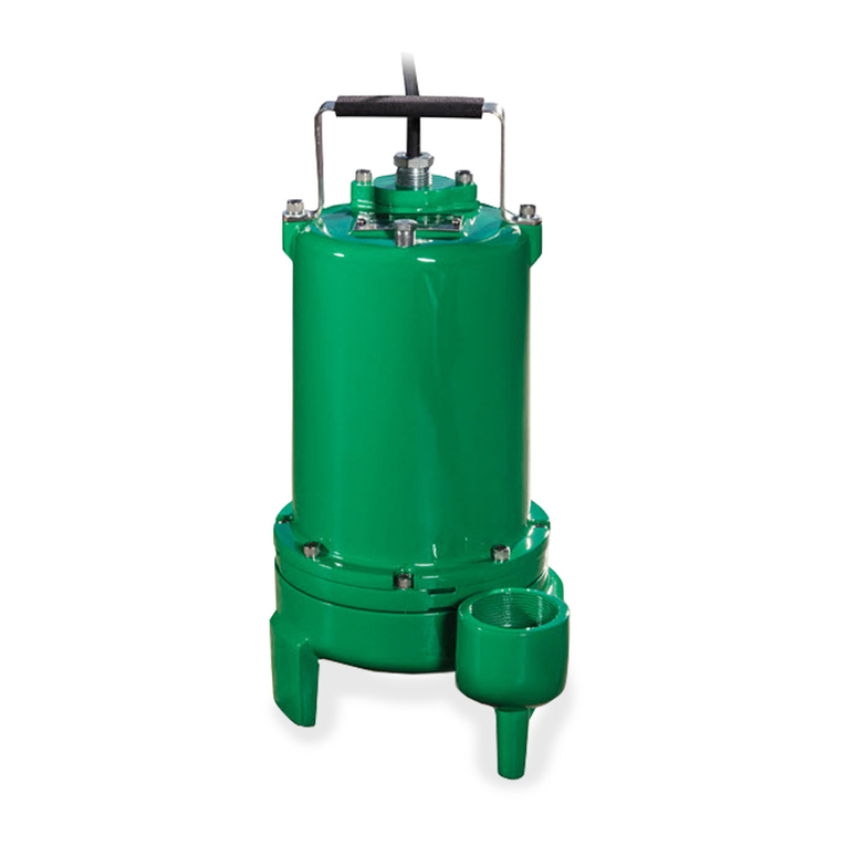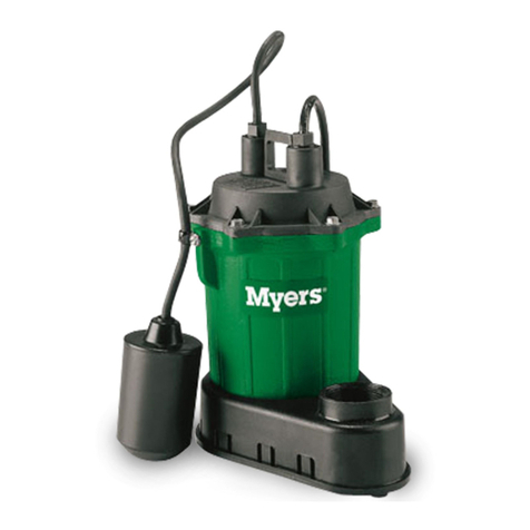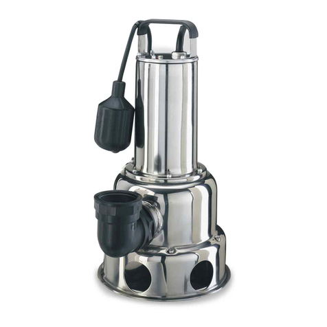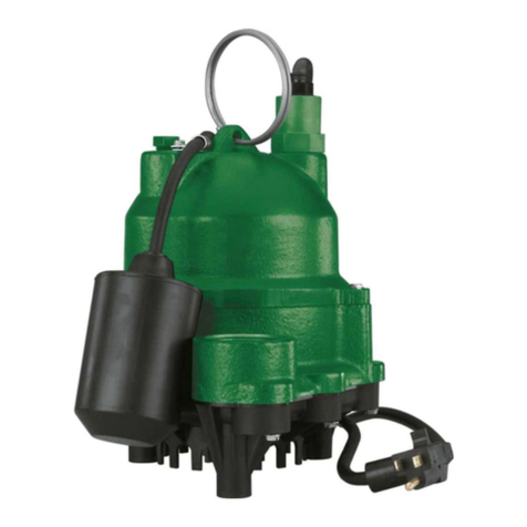
DESCRIPTION AND APPLICATION
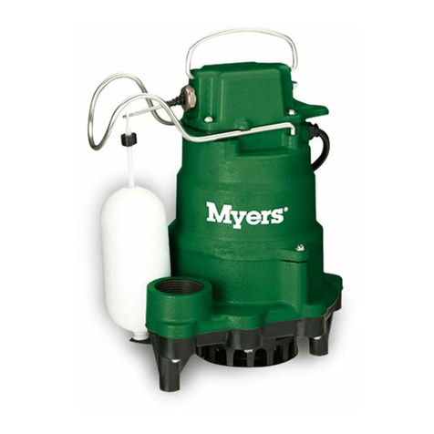
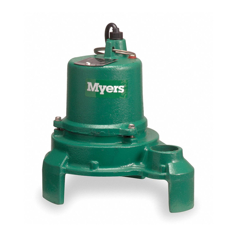
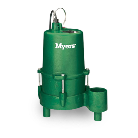
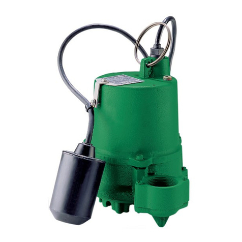
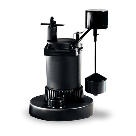
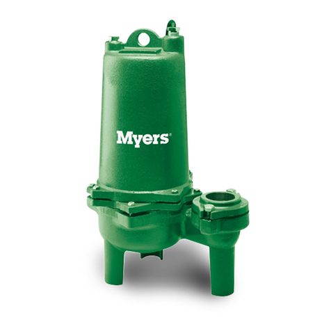
S40HT series pumps are single seal units, available in
automatic and manual versions. These pumps are
designed for use in pumping high temperature liquids
that do not exceed 195°F (90°C). These pumps are
not designed for pumping potable water. These pumps
are not for use in swimming pools, decorative foun-
tains, or any installation where human contact with
pumped fluid is common or possible.
S40HT series pumps use a 4/10 HP shaded pole, 1550
RPM motor, and are available in 115 volt, single phase.
All pumps are supplied with a 20’ power cord. All
automatic pumps are supplied with a mechanical
(mercury-free) piggy-back float switch rated for high
temperature use. The S40HT series pumps are
designed to pass ¾” spherical solids. Pump impellers
are Class 20 cast iron vortex design. All pumps have
1½” NPT discharge.
AIR LOCKING
A pump is said to be air locked if water traps air in the
pump and it cannot get out, thus preventing the pump
from operating. S40HT series have 1/8” air vent hole in
the impeller chamber to let out trapped air. If this hole
becomes plugged, pump may air lock. As a secondary
precaution a 1/8” hole should be drilled in the discharge
pipe below the check valve. The check valve should be
12” to 18” above pump discharge. Do not put check
valve directly into pump discharge opening.
PACKAGING
Each pump is packaged separately in a carton marked
with a catalog number and Myers engineering number.
The pumps are carefully packaged to prevent damage
in shipping. However, occasionally damage may result
due to rough handling. Carefully go over pump and
check for damage that could cause pump to fail.
LEVEL CONTROLS
All S40HT-11P pumps are supplied with a 20 foot
mechanical (mercury-free), piggy-back float switch.
The piggy-back switch is tethered directly to pump.
The switch must float free from pump and basin wall.
Plug the switch cord plug into a properly grounded,
rated voltage receptacle. Plug the power cord into the
back of the switch cord and tape the cords to the
discharge pipe approximately every 12”. The power
receptacle must be located outside the wet sump or
basin due to the DANGER of current leakage.
MOTOR TYPE
The motors used in the S40HT series pumps are
pressed into the cast iron housings and surrounded by
dielectric oil for superior heat dissipation. All models
use a 4/10 HP shaded pole, 1550 RPM motor. All
models have Class F motor windings, are available in
115 volts with overload protection, and use a double
sleeve bearing design. These pumps have no starting
switches and do not require a control panel for
individual installations.
INSTALLATIONS
Basin or tanks must be vented in accordance with local
plumbing codes. These pumps are not designed for
and cannot be installed in locations classified as
hazardous in accordance with the National Electrical
Code ANSI/NFPA 70.
When installing S40HT series pumps in high tempera-
ture installations, ALL basins, tanks, piping, fittings,
additional floats and cables must have rating ex-
ceeding 195°F (90°C). Also pumps are not to be used
in environments where ambient temperatures exceed
195°F (90°C).
CAUTION: If pump is to be used for pumping sewage
effluent: never enter pump chamber after sewage or
effluent has been in basin. Sewage water can give off
methane, hydrogen sulfide and other gases which are
highly poisonous.
Myers recommends installing effluent pumps with a
quick removal systems. The quick removal system
may be a union or Cam-lok coupling if the pipe is within
reach from the surface, or a rail system type quick
disconnect on deeper installations.
The dosing tank or pumping chamber must be con-
structed of corrosion resistant materials and must be
capable of withstanding all anticipated internal and
external loads. It also must not allow infiltration or
exfiltration. The tank must have provisions for anti-
buoyancy. Access holes or covers must be adequate
size and be accessible from the surface to allow for
installation and maintenance of the system. Access
covers must be lockable or heavy enough to
prevent easy access by unauthorized personnel.
The pumping chamber holding capacity should be
selected to allow for emergency conditions.
The discharge pipe must be the same size as the
pump discharge, 1½” or larger. In order to insure
sufficient fluid velocity to prevent any residual solids
from collecting in the discharge pipe, it is recom-
mended that a minimum flow of 2’ per second be
maintained (12 GPM through 1½” pipe, 21 GPM
through 2” pipe and 46 GPM through 3” pipe). A full
flow (ball or gate) shut off valve must be installed to
prevent back flow of effluent if the pump must be
removed for service. A check valve must be installed
on pressure sewer systems to prevent backflow and to
reduce wear on the pump system.
A high water alarm must be installed on a separate
circuit from the pump circuit. The alarm should have
the ability to be tested for proper operation.
3
