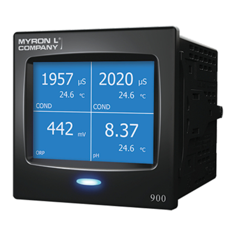
Myron L 900 Series User manual

Page 1 of 8
Quick Start Guide
MYRON L
®
COMPANY – 900 SERIES MULTI-PARAMETER MONITOR/CONTROLLER™ – MODELS 900M-1C AND 900M-3C
This Quick Start Guide will give you the basic installation and
setup instructions. For a comprehensive set of instructions,
including detailed operating instructions, advanced settings,
calibration instructions, maintenance procedures, and
accessories, download the 900 Series Multi-Parameter
Monitor/Controller Operation Manual from
www.myronl.com.
I. UNPACKING AND INSPECTION OF EQUIPMENT
1. Inspect the shipping container. If it is damaged, contact
the shipper immediately for instructions. Do not discard
the box.
2. If there is no apparent damage, unpack the container. Be
sure all items shown on the packing list are present. If
items are missing, notify the supplier immediately.
Contents of model 900M-1C includes:
Ø900 Series Monitor/Controller
ØPanel Mounting Brackets – 2 ea.
ØScrews – 2 ea.
ØFerrite Bead
ØQuick Start Guide
ØMating Connectors for: Power Supply Input, Relay
(1ea.), 4-20 mA Input, Flow Switch Input (with jumper),
Flow/Pulse Input, RTD Input, Recorder Output, and
Shorting BNC Protective Cover
Ø2.0 mm Standard Screwdriver (for terminal blocks)
ØRemote Alarm Harness (1 ea.) with wire nuts (2 ea.)
Contents of model 900M-3C includes:
Ø900 Series Monitor/Controller
ØPanel Mounting Brackets – 2 ea.
ØScrews – 2 ea.
ØFerrite Bead
ØQuick Start Guide
ØMating Connectors for: Power Supply Input, Relays (3
ea.), 4-20 mA Input, 4-20 mA Out, Flow Switch Input
(with jumper), Flow/Pulse Input, RTD Input, Recorder
Output, and Shorting BNC Protective Cover
Ø2.0 mm Standard Screwdriver (for terminal blocks)
ØRemote Alarm Harness (2 ea.) with wire nuts (4 ea.)
WARNING
PLEASE READ AND COMPREHEND ALL WARNINGS, CAUTIONS, ADVISEMENTS AND INSTRUCTIONS
CONTAINED WITHIN THE FULL 900 SERIES OPERATION MANUAL PRIOR TO INSTALLING OR OPERATING THIS
EQUIPMENT. FAILURE TO COMPLY IS BEYOND THE RESPONSIBILITY OF THE MYRON L®COMPANY.
WARNING
Ensure power is off while installing electrical equipment. If monitor/controller is installed, ensure the power is off before
servicing. Failure to do so could cause damage to the instrument and could be harmful or fatal to personnel. Only qualied
personnel should install or service electrical equipment. Install all wiring to comply with applicable electrical codes.
WARNING
The 900 Series Multi-Parameter Monitor/Controllers operate on 12-24 VDC or 24 VAC. Before applying power
ensure the input power supply is correct. Failure to do so is beyond the responsibility of the Myron L®Company.
WARNING
If there are cracks or ANY damage to the front panel or touch screen of the instrument:
• DO NOT touch the instrument.
• Immediately remove main power from the instrument’s power input and all relay contacts by interrupting them at
the mains power panel switches or circuit breakers.
Replace the instrument.
3. Record identication information on page 8 of this guide.
II. BASIC SETUP
1. Install the base unit.
2. Install all sensors.
3. Connect all sensors, inputs, and outputs to the 900.
4. Power up the 900 and go through the “INITIAL SETUP” procedure.
5. Program “DETAILED SETTINGS” custom to your application.
6. Calibrate as necessary.

Page 2 of 8
1. After selecting the mounting location, mark the appropriate panel cutout and complete the necessary cuts. Deburr the
cutout edges to prevent damage and to allow for a watertight seal.
a. Or you can use one of the optional mounting brackets.
2. Verify the panel gasket on the 900 is positioned against the back of the bezel.
3. Gently insert the 900 through the panel cutout; ensuring the panel gasket remains at and properly aligned between the
bezel and the panel.
4. Gently insert the 900 through the panel cutout; ensuring the panel gasket remains at and properly aligned between the
bezel and the panel.
5. While holding the front of the instrument rmly to the panel, insert panel clamps into the sides of the 900, and slide forward
to the back of the panel.
6. Insert the screws and tighten the panel clamps to secure the 900. The gasket should be evenly compressed to 50% of its
original thickness (this will leave approximately 0.05”/1.27 mm gap between the bezel and panel). Do NOT over-tighten.
7. Verify the panel gasket has remained properly installed between the bezel and panel.
NOTE: It is suggested that the user mount watertight restraint xtures with strain relief as well as a service loop on all cabling. All
cabling should be routed using best practices to protect from damage and/or signal interference. Consider grounded steel conduit
to protect against EMI interferences (such as RF).
B. Panel Mounting
III. INSTALLING THE 900 SERIES MULTI-PARAMETER MONITOR/CONTROLLER
WARNING
Under no circumstances may the device be installed or removed while under voltage! This poses the risk of
electrocution. Switch-off the entire system beforehand. This work must be performed only by qualied personnel!
The device must never be installed in potentially-explosive areas! There is the risk of an explosion.
WARNING
For protection against electrical shock hazards, the equipment must be directly connected to an approved power
supply with the power supply cord set which is provided by the manufacturer.
Do not use an ungrounded receptacle. Any break in the electrical ground path could be hazardous.
If the power cord becomes cracked, frayed, broken, or otherwise damaged, it must be replaced
Do not replace with a lower rated cord set.
WARNING
A switch or circuit-breaker must be included in the installation;
It must be easily reached;
It must be marked as the disconnecting device for the equipment power supply.
WARNING
The sides and back of the 900 Series Monitor/Controller must be protected from:
• Stream or spray of water.
• High-humidity, condensing atmosphere.
• High dust environments.
If there is a likelihood that the sides or back of the instrument could be exposed to one of these conditions, the 900
Series Monitor/Controller must be installed in an appropriate type of humidity controlled, water-proof and/or dust-
proof enclosure.
WARNING
To maintain the IP65 rating of the front panel and IEC61010-1 Safety certication of the entire instrument it must be:
• Panel mounted.
• Mounted in such a way as to protect the front panel from impacts ≥ 1 joule.
WARNING! These products can expose you to chemicals including Di(2-ethylhexyl)phthalate (DEHP), which is known
to the State of California to cause cancer and birth defects or other reproductive harm. For more information go to
www.P65Warnings.ca.gov.
NOTE: The 900 should be mounted prior to connecting cabling.
A. Select a Mounting Site
When selecting a location for the 900, avoid locations subject to direct sunlight, as well as temperatures or humidity outside
the specied ranges. Be sure to leave sufcient space in the back of the panel for connectors, cabling with a service loop, and
ventilation. The 900 should be mounted on a vibration-free structure, in a location where liquids will not be splashed on it. Any
water splashed on the LCD should be immediately wiped dry using a soft absorbent cloth.
For optimal viewing and programmability, the display should be at eye level.

Page 3 of 8
CAUTION
COVER TO REMAIN IN PLACE UNLESS
CONTROLLER CARD INSTALLED
Power Input
Relay #2
Remote Alarm #2
Relay #3
pH / ORP Input
mV Input
Pulse Input
COND / RES 2
Relay #1
RS-485
4-20 mA Output
4-20 mA Input
0-10VDC / Recorder Output
RTD Input
Flow Switch Input
COND / RES 1
Remote Alarm #1
A. Back Panel Connector Locations (Model 900M-3C shown)
B. Wiring Inputs and Outputs to the Connectors
The terminal block connectors should be unplugged from the back of the 900 prior to attaching cable wires. If routing the cable
through a conduit or strain relief, you should do that before attaching the terminal block connector.
The following diagrams are the basic wiring for each input/output with its corresponding terminal block [TB: XXX]. Each wire
should be stripped and tinned approximately ¼ inch. Insert each wire into its corresponding slot, then, using the small 2 mm
screwdriver (included in the kit), tighten each wire securely by turning the screw in a clockwise direction.
For more detailed information and alternate wiring options, see Detailed Operating Instructions in the full Operation Manual.
IV. ELECTRICAL INSTALLATION
The electrical installation procedures provided here are common to all 900 Series Multi-Parameter Monitor/Controllers. The 900
Series are powered by 24 VAC/12-24 VDC. Before starting, ensure the input power supply is correct. Failure to do so is beyond
the responsibility of the Myron L®Company. Refer to the Back Panel Connector Locations illustration (below) for the location of
input/output terminal blocks.
NOTE: It is suggested that the user create a service loop on all cabling during installation.
NOTE: A device to disconnect the 900 Series Monitor/Controller from the power supply must be installed. This switch or circuit breaker
should be clearly labeled as the disconnection device for the Model 900.
WARNING
To maintain the 900 Series Multi-Parameter Monitor/Controller IEC 61010-1 safety rating, only use external power
supplies/adapters that are also IEC/UL 61010-1 or IEC/UL 60950-1 rated to the full operating temperature range of
the instrument.
• ALWAYS make sure that the ferrite bead supplied with the 900 Series is installed around the power input cabling.
WARNING
When installing relays, to avoid a possible hazardous condition:
• Make sure that the wiring used to connect the relays to the 900 Series Monitor/Controller relay outputs is at least
14 AWG.
• Power switched by the relays must not exceed 250 VAC/8A or 30 VDC/5A.
WARNING
If using a power supply other than one supplied by Myron L®Company, the cable of that power supply must meet
the following minimum requirements:
• 24-gauge, copper wire.
• Rated for 12-24 VDC or 24 VAC at 1 Amp.
Make sure that appropriate voltage and current ratings are met before applying the power to 900 Monitor/
Controller.

Page 4 of 8
TB: COND / RES 1, COND / RES 2
Green
Red
Neutral
Sensor:
Conductivity, Resistivity, TDS, or Salinity
White
Black
Green
Red
Orange
White
Black
TB: pH / ORP
Sensor: pH / ORP
Neutral
Ground (GND)
Flow / Pulse Input
18V Output (18V)
Auxiliary
TB: FLO/PULSE
Flow / Pulse Input
Remote Alarm
TB: RA #1, RA #2
Positive (+)
Negative (-)
4-20 mA Output
TB: 4-20 mA OUT
Signal Out (SIG)
Power In (+)
Power Out (-)
Power Input
TB: 24 VAC 12-24 VDC
Negative (
-
)
Positive (+)
Ground (GND)
Negative (-)
Recorder Output
TB: REC O/P
Positive (+)
Relay
TB: RELAY #1, RELAY #2, RELAY #3
Normally Open (NO)
Common (C)
Normally Closed (NC)
Flow Switch Input
TB: FLOW SW
( )
+( )
-
RTD Temperature Input
TB: RTD
21
Negative (-)
4-20 mA Input
TB: 4-20 mA IN
Positive (+)
NOTE:When there is NO ow or level switch installed in the Flow Switch Input, the jumper (included) must be installed in the
Flow Switch terminal block connector on the back of the 900.
C. Connecting Inputs, Outputs, and Power to the 900
The 900 Series Multi-Parameter Monitor/Controllers utilize pluggable terminal blocks. Once
the connectors are wired, with the power supply OFF, simply plug each connector into the
corresponding terminal block (See Back Panel Connector Locations above). If a ferrite bead is
not already in place, wrap the power input cable around a ferrite bead (included with the 900) 4
inches from the terminal block connector. Once everything is installed and connected, simply turn
the power supply
ON, and begin programming. The rst time the 900 is powered up, it will go into
the Initial Setup (see section V).
V. INITIAL SETUP
When you power-up the 900 for the rst time it will display the Myron L®Company Logo for a few seconds, then go to the
“Initial Setup” screen. Here you will set the Date/Time, Location, Passwords, enable (activate) Input Channels, and select
Screen Layout.
Initial Setup Screen
The Initial Setup will walk you through each of the initial system settings, beginning with Date/Time. Once the Date/Time is set
up, the display will go directly to the “Set Up Location Info” screen.
On the “Initial Setup” screen, white text indicates an active eld, and gray text
indicates a eld that has not yet been activated.
A. Set Up Date and Time
To set the date and time:
1. Tap the “Date/Time” eld.
2. Tap the date eld.
a. Tap the date format you prefer; MM/DD/YYYY, DD/MM/YYYY or YYYY/MM/DD.
b. Tap the
NEXT
button. The display will go to the “Adjust Date” screen.
c. Using the up and down arrows, set the correct date.
d. Tap the
ACCEPT
button. The display will return to the “Set Up Date and Time”
screen.
Initial Setup 7:08 PM
Password
Location
Date / Time
Input Channel
ACCEPT

Page 5 of 8
3. Tap the time eld.
a. Tap the time format you prefer; “12 Hour” or “24 Hour”.
b. Tap the
NEXT
button. The display will go to the “Set Up Time” screen.
c. Using the up and down arrows, set the correct time.
d. Tap the
ACCEPT
button. The display will return to the “Set Up Date And Time” screen.
4. When you are satised with the date and time settings tap the
NEXT
button. Continue to section B. Set Up Location
Information.
B. Set Up Location Information
The “Location Information” function allows you to program the device name, location, and/or user specic information to
identify each instrument. To enter location information from the “Set Up Location Info” screen:
1. Tap the box to the right of the eld you wish to enter. An alphanumeric keypad will be displayed.
2. Enter the desired data (up to 9 characters per eld) then tap the OK button.
3. Repeat steps 1 and 2 to enter additional location elds.
4. When you are satised with the Location Info, tap the
NEXT
button. Continue to section C. Set Up Password Security.
C. Set Up Password Security
The “Password” feature allows you to set password protection for different levels of access. Once set up, the administrator will
be able to limit the access of operators to prevent unauthorized changes in settings/conguration.
NOTE: Once the administrator password is set, it may only be changed or reset using that password or by contacting the
Myron L®Company.
Make sure the administrator’s password is recorded in a secure location. If this password is lost the instrument CANNOT be
reprogrammed without contacting the Myron L®Company.
For more detailed information on password security, download the full Operation Manual.
If you wish to skip the password setup at this time, simply tap the
NEXT
button and skip to section D. Enable Input
Channels.
To set up the Password feature from the “Setup Password: Select User” screen:
1. Set Up Administrator Password.
a. Tap the “Administrator” eld. The display will go to the “Set Up Security” screen.
b. Tap the “Setup Password” eld.
c. Tap the “New Password” eld.
d. Enter the desired administrator password (up to 8 characters) then tap the OK button.
e. Tap the “Conrm Password” eld.
f. Re-enter the administrator password then tap the OK
button.
g. If you are satised with your password, tap the
ACCEPT
button. The display will return to the “Set Up Security”
screen.
2. Set Up Operator Access.
a. Tap the “Operator Access” eld.
b. Tap the box to the left of each function you want
operators to have access to.
• Green box indicates allowed access.
• Blue box indicates denied access.
c. When you are satised with the access settings, tap the
ACCEPT
button. The display will return to the “Set Up
Security” screen.
d. Tap the
BACK
button. The display will return to the “Setup Password: Select User” screen.
3. Set Up Operator Password.
a. Tap the “Operator” eld. The display will go to the “Set Up Security” screen.
b. Tap the “Setup Password” eld.
c. Tap the “New Password” eld.
d. Enter the desired operator password (up to 8 digits) then tap the Enter button.
e. Tap the “Conrm Password” eld.
f. Re-enter the operator password then tap the Enter button.
g. If you are satised with the operator password tap the
ACCEPT
button.
h. Tap the
BACK
button. The display will return to the “Set Up Password: Select User” screen.
i. Tap the
NEXT
button. Continue to section D. Enable Input Channels.
Select Operator Access 7:08 PM
View Settings
Relay / Alarm
Measurement
System Settings
Adv. Settings
ESC ACCEPT

Page 6 of 8
D. Enable Input Channels
Each connected sensor/input must be enabled in order to operate. There must be
at least one input channel enabled or an Error screen will be displayed.
To enable input channels:
1. Tap the box to the left of each input channel you wish to enable.
• Green box indicates the input channel is enabled.
• Blue box indicates the input channel is disabled.
2. When you are satised with the status of each input channel, tap the
ACCEPT
button. Continue to section E. Screen Layout.
E. Screen Layout
The 900 allows you to customize the layout of the screen displayed during normal
Operating mode. This is done from the “Select Screen Layout” screen.
To select the Screen Layout:
1. Tap on the desired screen layout. The text of the selected option will turn
white.
2. Tap the
ACCEPT
button.
3. The 900 will go directly into normal Operating Mode. Upon initial
activation, the 900 will populate the display locations with enabled input
channels using the default hierarchy.
NOTE: If the “Single Channel” screen layout is selected the display will cycle
through the enabled input channels. To lock the screen on a specic input channel,
simply tap the lock icon on the bottom right side of the screen.
Indicates the screen is unlocked (the screen will cycle through enabled
input channels).
Indicates the screen is locked (the selected input channel will remain on
the screen).
To change between locked/unlocked status, simply tap on the lock icon.
Select Input Channel 7:08 PM
COND/RES1
COND/RES2
mV IN
RTD
pH/ORP FLO/PULSE
4-20mA IN Select All
ESC ACCEPT
Select Screen Layout 7:08 PM
Dual Channel
Single Channel
All Channels
Triple Channel
Quadruple Channel
ESC ACCEPT
NOTE: On the Dual, Triple, or Quadruple Channel screen layouts, you can re-arrange the location (conguration) of
measurements on the screen. Simply tap the location you wish to change, tap the
ADJUST
button, then using the left or right
arrows select the input channel you wish for that location on the screen, tap the
ADJUST
button again and then tap the gray
measurement value. Repeat for each location on the screen. For more detailed instructions see the “Display Settings/Screen
Conguration” section of the Operation Manual.
Normal Operating Screen
(Example below is the Single Channel screen layout)
The Initial Setup now is complete. Continue on to the Detailed Operating Settings to set up sensors and select
measurement types for each enabled input channel.
For a comprehensive set of instructions, including detailed operating instructions, advanced settings, calibration
instructions, maintenance procedures, and accessories, download the 900 Series Multi-Parameter Monitor/Controller
Operation Manual from www.myronl.com.
VI. DETAILED OPERATING SCREEN
The “Detailed Operating Screen” will display the basic settings of the selected input channel. This screen is also the base point
from which all settings are accessed after the initial setup.
2020
24.9
COND
R1 A1
µS
° C
Primary Unit of Measure
Secondary Unit of Measure
Screen Lock
Secondary Measurement Value
Primary Measurement Value
Linked Relays and Alarms
Measurement Type/Input Channel

Page 7 of 8
To access the “Detailed Operating Screen” from the normal operating screen, simply tap the measurement value of the
input channel you wish to view/edit.
NOTE: If the input channel you wish to view/edit is not displayed on the normal operating screen, you can tap any
measurement value to access the “Detailed Operating Screen”, tap the
ADJUST
button to enter edit mode, then tap the
left or right arrows until the input channel you wish to view/edit is displayed. The text of editable elds will be white. The
system will remain in edit mode until you tap the
ADJUST
button again.
System Settings, Display Settings, Relay/Alarm settings and Advanced settings can be accessed from any “Detailed
Operating Screen”.
NOTE: To exit edit mode tap the
ADJUST
button again (the text of the editable elds will turn gray indicating they are no
longer editable). To return to normal operating mode, while the text is gray, tap the measurement value.
While in edit mode, the following items may be available for setup/adjustment (depending on input channel selected):
Detailed Operating Screen
• Screen Title: Indicates the current screen’s title.
• Input Channel: Indicates which input channel is selected. When in edit mode, allows you to access sensor settings for
the selected input channel.
• Measurement Type: Indicates the current measurement type for the selected input channel. When in edit mode, tapping
this button allows you to select the measurement type. (Example: COND/RES1 or COND/RES2 input channel
measurement types are conductivity, resistivity, TDS, or salinity.)
• Left Arrow: Tapping this arrow brings you to the previous input channel’s “Detailed Operating Screen”.
• Primary Measurement Value: Displays current primary measurement value. When in edit mode, tapping this value allows
you to calibrate the selected input. See the Calibration section of the full Operation Manual.
• Secondary Measurement Value: Displays current secondary measurement value associated with selected input (usually
temperature). When in edit mode, tapping the value allows you to calibrate the selected measurement.
• Linked Relays/Alarms: Indicates relay(s)/alarm(s) associated with the selected input channel.
• Solution Type: Indicates the tempco solution type (if applicable). When in edit mode, tapping this button allows you to
edit the solution type/tempco for the selected input.
• Relays and Alarms Button: When in edit mode, tapping this button brings you to the relay/alarm setting screen.
• Right Arrow: Tapping this arrow brings you to the next input channel’s “Detailed Operating Screen”.
• Primary Unit of Measure: Displays the primary measurement’s unit of measure.
• Secondary Unit of Measure: Displays the secondary measurement’s unit of measure.
• Adjust Button: Tapping this button puts the instrument in or out of edit mode.
• Settings Button: When in edit mode, tapping this button brings you to the main settings menu.
VII. DETAILED OPERATING SETTINGS
The following settings are required for measuring conductivity, resistivity, TDS, salinity, pH, ORP or mV.
A. Sensor Settings
To select sensor models and enter sensor settings from the desired input channel’s “Detailed Operating Screen”:
1. Tap the
ADJUST
button to enter edit mode.
2. Tap the input channel button on the top center of the screen. The display will go to the “Select Sensor” screen with the
sensors available for the selected input channel.
3. Using the up and down arrows, select the sensor model then tap the
ACCEPT
button.
4. Tap the “Cable Length” eld. Enter the sensor cable length then tap the Enter button.
5. Tap the “Length Unit” eld. Tap on the desired length unit then tap the
ACCEPT
button.
2020
24.9
R1 A1
µS
° C
Primary Unit of Measure
Secondary Unit of Measure
Secondary Measurement Value
Primary Measurement Value
Linked Relays and Alarms
RELAY
COND/RES1COND
Detailed Operating Screen 7:08 PM
ADJUST
SETTINGSKCI
Relays and Alarms Button
Right Arrow
Left Arrow
Measurement Type
Input Channel
Screen Title
Adjust Button
Settings Button
Solution Type

Page 8 of 8
© Myron L Company 2020 900MQSI r03-20a
Specications subject to change without noticePrinted in the U.S.A.
6. Tap the “Ω/Length” eld. Enter the cable resistance then tap the Enter button.
• Myron L®Company conductivity, resistivity, TDS, and salinity sensor cables are 0.01614 Ω/ft or 0.05295 Ω/m
• Myron L®Company pH and ORP sensor cables are 0.02567 Ω/ft or 0.08422 Ω/m
7. For conductivity, resistivity, TDS, and salinity only: Tap the Cell Constant eld. Enter the
cell constant then tap the
Enter
button. (The cell constant is the number preceded
by “K=” located on the label on the sensor cable. Example shown is “0.8506”.)
8. Tap the
ACCEPT
button. The display will return to the “Detailed Operating Screen”.
B. Measurement Type
To select the measurement type from the desired input channel’s “Detailed Operating Screen”:
1. Tap the
ADJUST
button to enter edit mode.
2. Tap the Measurement Type button on the upper left side of the screen. The display will go to the “Select Measurement
Type” screen with the measurement types available for the selected input channel and sensor.
3. Tap desired measurement type. The text of the selected measurement type will turn white.
4. Tap the
ACCEPT
button. The display will return to the “Detailed Operating Screen”.
5. Tap the gray measurement value to return to the normal operating mode.
For a comprehensive set of instructions, including detailed operating instructions, advanced settings, calibration instructions,
maintenance procedures, and accessories, download the 900 Series Multi-Parameter Monitor/Controller Operation Manual
from www.myronl.com.
INSTRUMENT IDENTIFICATION RECORDS
Model Number: ________________________________________________________________________________________________
Serial Number: _________________________________________________________________________________________________
(The model and serial numbers appear on the labels located on the side of the instrument.)
Date of Purchase: _______________________________________________________________________________________________
(This is the warranty start date.)
Installation Location: ____________________________________________________________________________________________
Asset ID (user assigned): _________________________________________________________________________________________
WARRANTY
All Myron L®Company 900 Series Multi-Parameter Monitor/Controllers have a TWO Year Limited Warranty. If any
Monitor/Controller fails to function normally, return the faulty unit to the factory prepaid. If, in the opinion of the factory,
failure was due to materials or workmanship, repair or replacement will be made without charge.
A reasonable service charge will be made for diagnosis or repairs due to normal wear, abuse or tampering. Warranty is
limited to the repair or replacement of Monitor/Controller only. The Myron L®Company assumes no other responsibility
or liability.
Sensors and Accessories are sold separately and carry their own warranties.
If you have any questions regarding this manual or need additional information, please contact our Technical Sales
®
2450 Impala Drive Carlsbad, CA 92010-7226 USA Phone: +1-760-438-2021
Website: www.myronl.com
CS951
K = 0.8506
PT1000
S/N 181749-03
Other manuals for 900 Series
1
This manual suits for next models
2
Table of contents
Other Myron L Controllers manuals