nanoradar NRA15 User manual

NRA15 millimeter wave radar
User manual
Hunan Nanoradar Science and Technology Co., Ltd.

Disclaimer
Thanks to purchase this product. There is web pages about NRA15 altimeter in our official
website (www.nanoradar.cn), which allows you to get the latest product information and
user manual. The user manual is subject to change without notice.
Please read this manual carefully before using this product. Once used, it is deemed to have
recognized and accepted the content of this manual. Please strictly follow the manual to
install and use the product. Any improper use may cause damage or injury, and Nanoradar
would not bear the corresponding loss and liability.
With the principle of continuous improvement and development, the company reserves the
right to modify and improve any product details described in the document without prior
notice. The contents of this manual are provided at the time of product manufacture, and no
explicit or tacit warranty is given to the accuracy, reliability and content of the document
unless required by applicable law.
To the maximum extent permitted by applicable law, the Company and its suppliers, under
any circumstances, shall not be liable for any special, incidental, incidental or indirect loss,
regardless of the cause of the loss.
Product copyright is retained by Nanoradar. Reproduction in any form shall not be done
without permission. The use of this product and manual shall not be pursued liability for
the patent.
This manual contains important information, please keep it for future use.
Version history
Date
Version
Version Description
2018-05-29
1.0
the 1st version of application manual on NRA15


I
Contents
1 Brief introduction of NRA15....................................................................................错误!未定义书签。
2 Matters needing attention in use...............................................................................错误!未定义书签。
3 Shipping list........................................................................................................................................... 1
4 Quick-to-use steps..................................................................................................................................2
4.1 Connecation cable installation..................................................................................................... 2
4.2 Test and use.................................................................................................... 错误!未定义书签。
5 Serial-port data parsing.......................................................................................................................... 4
5.1 NRA15 configuration(Sensor Configuration)..............................................................................5
5.2 NRA15 back(Sensor Back).......................................................................................................... 6
5.3 NRA15 system status (Sensor Status)..........................................................................................7
5.4 Targets output status(Target Status)............................................................................................. 7
5.5 Target output information(Target Info)........................................................................................ 8
6 Data parsing examples............................................................................................................................9
7 Frequently asked questions (FAQ)........................................................................... 错误!未定义书签。
8 References................................................................................................................ 错误!未定义书签。

1
1 Brief introduction of NRA15
NRA15 is compact K-band radar altimeter developed by Hunan Nanoradar. It adopts
24GHz-ISM frequency band, with the advantages of 2cm measuring accuracy, small size, high
sensitivity, light weight, easy integration and stable performance, which satisfies the application
requirements in unmanned aircraft system (UAS), helicopters, small airships and other field.
2 Matters needing attention in use
Much attention should be paid to the "matters needing attention".
(1) Please make sure no obstructions under the radar during installation in order to ensure
accurate detection data. Because The radar determines the height of the drone by transmitting
MMW downwards.
(2) Please make sure that the radar module is vertically down during installation to ensure
accurate detection data.
(3) The radar cannot be installed near the nozzle of the atomizer to prevent the pesticide from
corroding the radar.
(4) The product has adopted shielding measures to avoid the adverse effects caused by
electromagnetic interference in space. Meanwhile, the radar should be away from
electromagnetic interference sources such as motors and suspended metal casings during
installation.
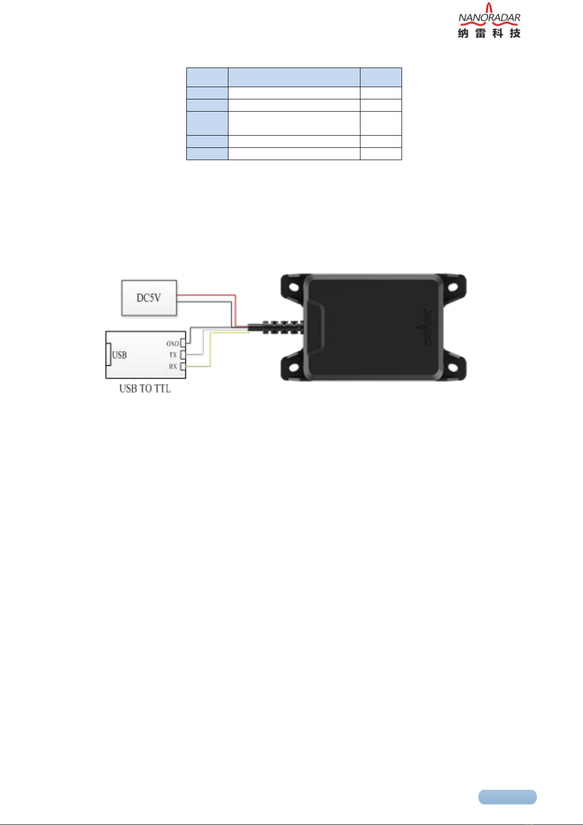
(5) The radar input voltage range is 5~20V DC, and the ripple is less than 20mv. An unclean
power supply will cause a number of fixed interference frequency components in the spectrum
during algorithm analysis, affecting the test results, and continuously output a target at a fixed
distance.
Any problem in installation, please feel free to contact Nanoradar.
3 Shipping list
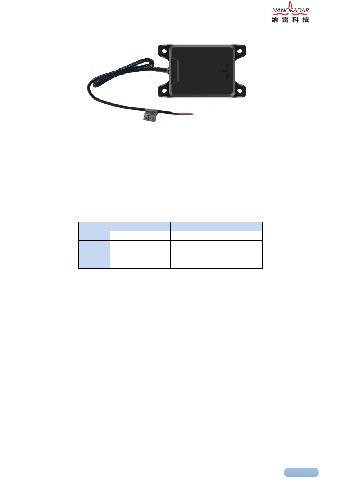
The shipping list includes:NRA15 sensor 1x and connection cable 1x , as shown in figure 1.

2
Figure 3 NRA15 sensor
5 sensor
4 Quick-to-use steps
4.1 Connection cable installation
The definition for NRA15 sensor interface pins are as shown in table 1.
Table 1 The definition for NRA15 pin interface
Pin No.
definition
value
color
1
POWER IN
4~6 V DC
red
2
GND
-
black
3
TTL USART_RX
0~3.3V DC
white
4
TTL USART_TX
0~3.3V DC
yellow
4.2 Test and use
NRA15 sensor data can be acquired and parsed by the "MMW Radar general Management
Tool" testing software, which is used to visually display the observation results. The tool is
helpful in the use of NRA15 sensor.
The UART serial port test method is as follows:
First of all, the "millimeter-wave radar general management tool" (PC test software), user
manual shall be provided by Nanoradar. According to the user manual, install and configure the
PC test software.
1) Test tools and software are as the following table:

3
Table 2 Product test and use tools
No.
Device name
Qty
1
NRA15
1
2
PC
1
3
Serial port adaptor to connect
USB to TTL
1
4
5V power adaptor
1
5
PC test software
1
2) With a USB connection to TTL serial port adaptor, to connect PC and NRA15, as shown in
figure 2 .
Figure 2 Diagram for serial port connection
Note:
Separately supply power from 5V DC stabilized power supply, and do not use 5V power
supply of USB2TTL adapter.
Input voltage range of 4 ~ 6VDC, ripple wave is less than 20mv. Unclean Power supply
will result in the appearance of a number of fixed interference frequency components in the
spectrum during the algorithm analysis, which would have an impact on test results and result in
the continuous target output in a certain fixed distance.
The TX and RX pins of the USB-to-TTL adapter need to be cross-connected to the TX and
RX pins of the NRA15 sensor.
3) USB serial-port adapter is connected to PC. And then open the PC test software to
configure parameters like in figure 5 (plug connection cable into the computer, then open the
PC software, the software will automatically detect the port). The red part in the figure is
parameter configuration of NRA15, while the blue part is the adjusted coordinate range

4
according to the test distance. Then click the right button "Connect to Device".
Figure 3 Radar PC test interface
4) Start to test. NRA15 radar antenna faces directly to the moving target, or there is relatively
small movement between the sensor and the target. You can see the target indicator of the red
triangle in the UI interface, and the target distance R. In Figure 5, the radial distance of the
target from the radar is 6.03 meters (NRA15 could detect the target within 100 meters to
ground). If no red triangle is indicated, it states that there is no target within the detectable
distance and field of view.
5 Serial-port data parsing
NRA15 radar sensor utilizes a UART-TTL interface with a default transmission rate of 115200
baud. Starting with a start sequence and terminating with a termination sequence for each data
message. At each data cycle of NRA15 (20ms), the message for NRA15 system status and
target output status would be output. If the field of detected target numbers in message of the
detected target output status is 1, the target output status message is followed by the target
output information message which contains the height parameter of the target.
PC or the peripheral device configures the NRA15 with the same message format, and the
corresponding message ID is 0x200.
A complete data message of UART-TTL communication is 14 bytes. Each byte of data is

5
unsigned8bit. The data range is 0 ~ 255 (0 ~ 0xFF). And the format is shown
in the following table. Each data message contains a message ID to distinguish between
different types of messages.
Table 3 Format of data message
Byte \ Bit
7
6
5
4
3
2
1
0
0
Start Sequence (2 x Uint8)
1
2
Message ID (2 x Uint8)
3
4
Data Payload (8 x Uint8 )
5
6
7
8
9
10
11
12
End Sequence (2 x Uint8)
13
The start Sequence is a constant value 0xAAAA, and the Message ID is defined as follows. The
Data Payload is defined according to the Message ID (see the next section). The End Sequence
is set to 0x5555.
Table 4 Definition of Message ID
Num
Message ID
Message Name
Comment
1
0x200
Sensor Configuration
NRA15 configuration
2
0x400
Sensor Back
NRA15 back
3
0x60A
Sensor Status
NRA15 status
4
0x70B
Target Status
Target output status
5
0x70C
Target Info
Target output
information
Note:
The Message ID is represented by 2 bytes, Byte2 is the low byte, and Byte3 is the high byte.
For example, the output of the NRA15 message is 0xAA 0xAA | 0x0A 0x06 | Data Payload |
0x55 0x55, which indicates that the message ID is 0x60A (NRA15 system status) and Data
Payload is the NRA15 system status.

6
5.1 NRA15 configuration(Sensor Configuration)
NRA 15 configuration message is shown in the following table. The start sequence (0xAAAA)
and the termination sequence (0x5555) have been omitted from the table.
Table 5 NRA15 configuration message format
Message ID
0x200
Signal Name
Bit
Resolution
Interval
Type
Comment
DataType
0..6
1
0…127
u7
1: Sensor ID
2: Sensor Version
3: Start/stop the target
information output
4: filter the range
7e: for internal test
7f: save parameter
R/W
7
1
0…1
u1
0: Read parameter;
1: write parameter
Parameter
8..31
1
-
u24
According to the
definition of Data Type
Reserved
32..63
1
-
u32
-
Note:
Currently, NRA15 only supports reading version information. Other functions are not yet
available. If R / W are 0, reading the parameters and the Parameter content is meaningless. If
the R / W are 1, that is, writing parameters, Parameter is defined according to DataType.
5.2 NRA15 back (Sensor Back)
After the PC or other MCU sends the configuration signal to NRA15, NRA15 will return the
execution result. The format is shown in the following table. The start sequence (0xAAAA) and
the termination sequence (0x5555) have been omitted from the table.

7
Table 6 NRA15 back message format
Message ID
0x400
Signal Name
Bit
Resolution
Interval
Type
Comment
DataType
0..6
1
0…127
u7
1: Sensor ID
2: Sensor Version
3:Start/stop,target
information output
4: range filtering
7e:for internal test
7f:Save parameters
Result
7
1
0…1
u1
0: fail to configure;
1:succeed to
configure
Parameter
8..31
1
-
u24
Defined according
to the DataType
Reserved
32..63
1
-
u32
-
Note:
At present, NRA15 will only return version information; other functions are not yet available.
DataType indicates the configuration item, result indicates the configuration result, and
Parameter is the value of the configured DataType.
5.2.1 Sensor Version
After the PC or other MCU sends the read version information of sensor to NRA15, the NRA15
will return the execution result. When the version information is returned, the corresponding
Parameter field format is as follows:
Table 7 Sensor Version back format
Message ID
0x400
Signal Name
Bit
Resolution
Interval
Type
Comment
DataType
0..6
1
2
u7
1: Sensor ID
2: Sensor Version
3: Start/stop
target information output
4: range filtering
7e: for internal test
7f: Save parameters
Result
7
1
0…1
u1
0:fail to read
1:succeed to read
Parameter
8..15
1
0…255
u8
Master Version
16..23
1
0…255
u8
Second Version
23..31
1
0…255
u8
Step Version
Reserved
32..63
1
-
u32
-

8
5.3 NRA15 system status (Sensor Status)
The NRA15 system status message format is shown in the following table. The start sequence
(0xAAAA) and the termination sequence (0x5555) have been omitted from the table, where the
value of RollCount is fixed to 0.
Table 8 NRA15 system status message format
Message ID
0x60A
Signal Name
Bit
Resolution
Interval
Type
Comment
ACTL_Mode
0..6
1
0…127
u7
NR15 is fixed to 1
RollCount
8..9
1
0…3
u2
The cycle count is
0-1-2-3, and it change
one time per cycle
Rsvd1
10..11
1
-
u2
-
CfgStatus
12..15
1
-
u4
NRA15 is fixed to 1
Rsvd2
15..63
1
-
-
5.4 Targets output status (Target Status)
The data message format for NRA15 system target output status is shown as in the table below.
The start sequence (0xAAAA) and termination sequence (0x5555) has been omitted for the
table, where the value of RollCount is continuously cycled between 0-1-2-3-0-1-2-3 ......
When the PC or an external MCU cannot process the output data of the NRA15 sensor in time,
it will cause the received RollCount value to be discontinuous. At this time a faster removal
methods should be found to solve this problem.
Table 9 NRA15 Targets output status message format
Message ID
0x70B
Signal Name
Bit
Resolution
Interval
Type
Comment
NoOfTarget
0..7
1
0…255
u8
The numbers of
detected targets
RollCount
8..9
1
0…3
u2
The cycle count is
0-1-2-3, and it change
one time per cycle
Rsvd1
10..63
1
-
u54
-
5.5 Target output information (Target Info)
The target output message format of NRA15 is shown in the following table. The start sequence

9
(0xAAAA) and the termination sequence (0x5555) have been omitted from
the table. When the radar sensor works normally and detects the target, it outputs the NRA15
system status message, and then outputs the target output status message, and finally outputs the
target output information message.
Table 10 NRA15 target output information format
Message ID
0x70C
Signal Name
Bit
Resolution
Interval
Type
Comment
Index
0..7
1
0…255
u8
Target ID
Rcs
8..15
-
0…255
u8
The section of
radar reflection
RangeH
16..23
0.01m
0…255
u8
Target distance
high 8 bit
RangeL
24..31
0.01m
0…255
u8
Target distance
low 8 bit
Rsvd1
32..39
-
-
u8
-
VrelH
40..42
0.05m/s
0..7
u3
-
Rsvd1
43..45
1
1
u3
-
RollCount
46..47
1
-
u2
NRA15 is fixed
to 0
VrelL
48..55
0.05m/s
0..255
u8
-
SNR
56..63
1dB
0..255
u8
Signal-Noise
Ratio
Note:
The value of each field in the table is not the true value of the target information. The true value
of the target information needs to be calculated through the following relations:
- Index = IndexValue
- Rcs = RcsValue*0.5 – 50
- Range = (RangeHValue*256 + RangeLValue)*0.01
- RollCount = RollCountValue
- SNR = Value-127
The target reflection Radar-Cross Section (RCS), the target range (Range), Signal-Noise
Ratio(SNR) can be obtained by these calculations, to accurately detect the targets.
6 Data parsing examples
Taking Message ID as an example, there is a frame of the Target Info data message as follows:
Target Info Data:

10
0xAA 0xAA 0x0C 0x07 0x01 0xC8 0x07 0xD0 0x00 0x02 0xEE 0x96
0x55 0x55
Description:
Start Sequence Message ID Data Payload End Sequence
Interpretation:
Start Sequence = 0xAAAA
Message ID = 0x0C + 0x07*0x100 = 0x70C
Data Payload = 0x01 0xC8 0x07 0xD0 0x00 0x02 0xEE 0x96
End Sequence = 0x5555
Each field of Data Payload is parsed as following:
Index = 1
Rcs = 0xC8*0.5 – 50 = 50
Range = (0x07*0x100 +0xD0)*0.01 = 20
Rsvd1 = 0
RollCount = (0x0 & 0xE0) >> 5 = 0
SNR = 0x96 – 127 = 23
Note:
The user needs to program to parse the sensor output data
(hexadecimal).
The data before being parsed is hexadecimal, and is decimal after
being parsed. 0x2AF5 hexadecimal is converted to decimal:
10997=5*16^0+F*16^1+A*16^2+2*16^3
7 Frequently asked questions (FAQ)
1) Q: What about the angular accuracy of NRA15?
NRA15 is a 24GHz mmw radar altimeter with 1T1R antenna, which is developed by Nanoradar.
It cannot measure the target angle. For the radar with more than two receiving antennas, it has
the ability to measure the angle. Besides, the more antennas it has, the higher accuracy of angle
resolution it could realize.
2) Q: In the height measurement of NRA15, which will it be subjected to when there is
vegetation and ground? When the ground is water, is it based on the ground surface or the water

11
surface?
A: NRA15 is MMW radar with high range accuracy developed by Nanoradar. In practical
application, the airflow under the aircraft is large if the height is less than 3m, and the
vegetation is likely to be blown away, so the reference point is the ground or water surface. If
the airplane reaches over 5m, the airflow would not affect the vegetation below. And if the
vegetation density is large, the reference point should be vegetation.
8 References
[1] White paper on NRA15 millimeter wave radar
[2] User manual for the general management system of Nanoradar mmw radar
Hunan Nanoradar Science and Technology Co., Ltd.
Tel.:0731-88939916
No.27 Wenxuan Road, Hi-tech District Changsha
E-Mail:sales@nanoradar.cn
B7 Lugu Compark
URL:www.nanoradar.cn

12
Table of contents
Other nanoradar Radar manuals
Popular Radar manuals by other brands

Leuze
Leuze LBK S-01 Original operating instructions

Endress+Hauser
Endress+Hauser Micropilot FMR53 technical information

Endress+Hauser
Endress+Hauser Micropilot M FMR230 operating instructions

BENDIX
BENDIX VORAD VS-500 Operator's manual

Bin Master
Bin Master NCR-80 Quick setup

Blackbe;rry
Blackbe;rry ITB100-1 installation guide

NorthStar
NorthStar 6 KW RADAR installation manual

Decatur
Decatur DragonEye Compact user manual

Bushnell
Bushnell Velocity 10-1911 How to use

Endress+Hauser
Endress+Hauser Levelflex FMP55 operating instructions

Fortem Technologies
Fortem Technologies TrueView R20 quick start guide

Axis
Axis D2110-VE user manual