NAPCO StarLink SLE Series User manual

StarLink™SLE Series Alarm Communicators -- Installation Instructions 1
and Contact ID. In addition, the SLE Control Center gener-
ates and reports a Supervisory signal in the event that the
network does not receive the expected supervisory test
signal from the wireless communicator during a pre-
scheduled period. The following models are available:
SLE-GSM-3/4G - 2G, 3G and 4G Network Compatible
GSM alarm capture Communicator, SIM card included.
Black plastic enclosure.
SLE-GSM-8D-3/4G - 2G, 3G and 4G Network Compatible
GSM alarm capture Communicator. Supports remote
downloading to the Gemini GEM-P400, GEM-P800,
GEMP-801, Express XP-400 and XP-600 series control
panels. SIM card included. Black plastic enclosure.
SLE-CDMA - Universal CDMA alarm capture Communica-
tor. Black plastic enclosure.
SLE-CDMA-8D - Universal CDMA alarm capture Commu-
nicator. Supports remote downloading to the Gemini
GEM-P400, GEM-P800, GEMP-801, Express XP-400
and XP-600 series control panels. Black plastic enclo-
sure.
ADDITIONAL COMPONENTS
In addition to the models listed above, the following sub-
assemblies are available:
SLE-DLEXT - Optional, for up/downloading, extends dis-
tance from radio to panel, from 10 feet, up to 100 feet.
See installation instructions WI1950.
SLE-DLCBL - Download Cable, 6 feet.
SLE-SMTCHG - Smart Charge Module, optional charger /
power supply.
SLE-ANTEXT - Extended antenna with 15 feet of cable.
SPECIFICATIONS
The following specifications apply to all StarLink radio mod-
els unless otherwise stated:
Electrical Ratings for +12V (all models powered by the
control panel)
Input Voltage: 15-10.6VDC
Input Current: 65mA with peak RF transmission current of
400mA for models SLe-GSM-3/4G and SLE-CDMA; (80mA
with peak RF transmission current of 400mA for model SLe
-GSM-8D-3/4G and SLE-CDMA-8D)
WI1936E 12/14
333 Bayview Avenue
Amityville, New York 11701
For Sales and Repairs, (800) 645-9445
For Technical Service, (800) 645-9440 or visit us at
http://tech.napcosecurity.com/
(Note: Technical Service is for security professionals only)
Publicly traded on NASDAQ Symbol: NSSC
© NAPCO 2014
INTRODUCTION
The StarLink™alarm capture radio communicators are fully
supervised, wireless digital two-way subscriber units sup-
ported by an extensive nationwide wireless network. All
models are compatible with virtually any 12VDC alarm con-
trol panel and are easy to install and test (always adhere to
the documentation provided by the control panel manufac-
turer). All can function as a backup to existing telephone
lines, or as a primary communicator when telephone lines
are absent and when connected directly to the control pan-
el Telco terminals. When used as a backup communicator,
all units will automatically switch the communication chan-
nel from the telephone line to the network when telephone
line trouble is detected.
The StarLink radio communicators use proprietary data-
capture technology that captures the alarm report from the
control panel and transmits the alarm signals to the SLE
Control Center; the alarm signals are then forwarded to
ANY Central Station via standard CS receiver formats 4/2
(((((((((( ) )))))))))
(1)
(2)
Control
Panel Network
Operator
SLE Control Center
(3)
CENTRAL
STATION (5) (4)
RADIO REPORTING PATH
The diagram below shows the transmission path of a
signal from the radio to the central station.
1. Signal from a Control Panel.
2. StarLink radio receives the signal
transmission (from the TIP an RING wires); sends
RF signal through the network operator.
3. Network Operator, part of the vendor system,
a section of the cellular spectrum.
4. SLE Control Center (NOC), receives and
routes data.
5. Central Station.
StarLink
Radio
StarLink™ SLE Series
Alarm Communicators
INSTALLATION INSTRUCTIONS

2 StarLink™SLE Series Alarm Communicators -- Installation Instructions
Electrical Ratings for the IN 1 Burg/Fire Input:
Input Voltage: 15-9VDC
Electrical Ratings for IN 2 and IN 3:
Maximum Loop Voltage: 15VDC
Maximum Loop Current: 1.2mA
End of Line Resistor (EOLR) Value: 10K
Electrical Ratings for 3 PGM Outputs:
Open Collector Outputs: Maximum Voltage 3V when ac-
tive; 15V maximum when not active
Maximum PGM Sink Current: 50mA
Physical (W x H x D)
Plastic Housing: 8 x 5-29/64 x 1½" (20.3 x 13.9 x 3.8cm)
Mounting: Plastic housing includes three keyhole slots for
triple gang boxes (see image at right and scale template on
page x);
Environmental
Operating Temperature: –10°C - 49°C (14°F - 120°F)
Humidity: Maximum 95% Non-Condensing
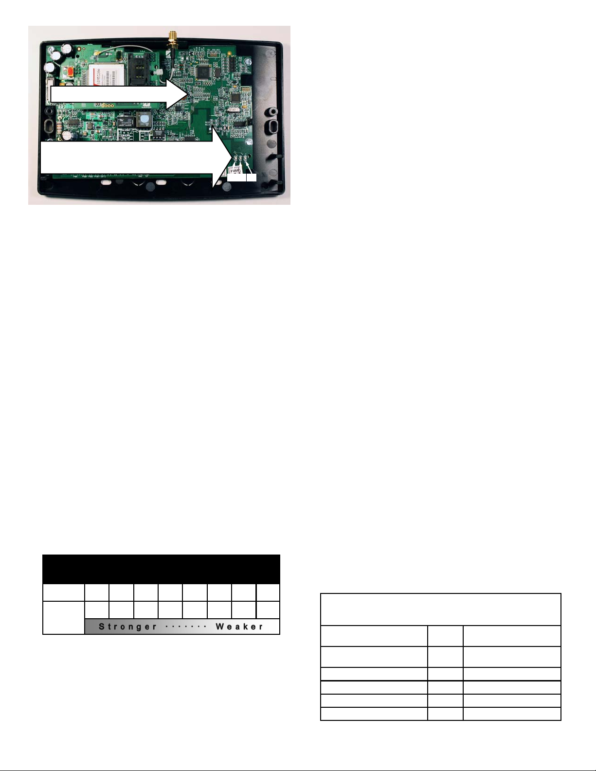
TERMINAL DESCRIPTIONS
Located at the bottom of the StarLink radio PC board, the
17 terminals are described as follows:
TB1: PWR (+12V)
(Refer to section "STEP 4: APPLY POWER")
TB2: PWR GND (–)
(Refer to section "STEP 4: APPLY POWER")
TB3: PGM1 (–): Open collector output. PGM1 is nor-
mally on (active low). When it is triggered (for ex-
ample, a trouble is detected) it becomes open col-
lector/high. To have a zone dedicated to an Star-
Link radio trouble, insert one side of the end of line
resistor into this PGM1 terminal, and wire the other
side of the resistor to the positive terminal of the
zone. The output can be re-configured to activate
on other conditions using the Management Center
screen (located at www.napconoc.com).
TB4: PGM2 (–): Open collector output. This output is
defaulted as "Fail to Communicate", and is normally
open collector/high. When a report fails to com-
municate, the output is active low. The output can
be re-configured to activate on other conditions us-
ing the Management Center screen (located at
www.napconoc.com).
TB5: PGM3 (–): Open collector output. This output is
defaulted as "Telephone Line Cut". When the 24V
telephone line voltage is correct, the output is open
collector/high; when the telephone line voltage is
too low, the output is active low. This output can be
re-configured using the Management Center screen
(located at www.napconoc.com).
TB6: IN 1 (B/F): Active high input intended for wiring
to the control panel bell output. When this input
detects a steady high, it sends a burglary alarm;
when it detects a pulsing temporal high, it sends a
Fire alarm; when it detects the "CO Alarm" pattern,
a CO alarm is sent. For this input to report to a cen-
tral station, the StarLink radio must be configured
with the central station telephone number and cor-
rect reporting formats and codes.
When used as arm/disarm status input, a high indi-
cates "armed" and a low indicates "disarmed".
Note: When using Napco Armed Lugs (E4 or
E15), do not use IN 1 for armed status; instead, use
IN 2 or IN 3.
TB7: IN 2: See TB9, below.
TB8: GND: Common ground terminal.
TB9: IN 3: Both terminals IN 2 and IN 3 are, by de-
fault, active low inputs. Use active low outputs to
activate. For these inputs to report to a central sta-
tion, the StarLink radio must be configured with the
Central station telephone number and correct re-
porting formats and codes. Jumpers 4 and 5 may
be used to make the IN 2 and IN 3 terminals super-
vised end of line resistor inputs that can be trig-
gered with N/O or N/C relay contacts. Wire the
common ground terminal GND (terminal TB8) to the
relay common. When used as arm/disarm status
input, a low indicates "armed" and a high indicates
"disarmed".
TB10: TIP: See TB11, below.
TB11: RING: Terminals TIP and RING: When used for
backup reporting, the street/cable-modem Tip and
Ring telephone wires must be routed from the out-
side to these terminals. These wires are monitored
for voltage such that if voltage falls below 1.5V, a
Telco Line Fault trouble is detected and the StarLink
radio switches over to apply its own Telco Line volt-
age to the control panel Tip and Ring, thus allowing
the StarLink radio to receive and transmit any
alarms sent by the control panel.
TB12: PANEL RING: See wiring diagrams.
TB13: PANEL TIP: See wiring diagrams.
TB14: RTS (R): See TB17 below.
TB15: PANEL TX (B): See TB17 below.
TB16: PANEL RX (G): See TB17 below.
TB17: CTS (Y): These terminals are wired to the SLE-
StarLink Plastic Housing Dimensions (inches)
8.0"
1-13/16"
3-5/8"
7-9/32"
5-29/64" 3-9/32" 3-9/32"
3-5/8"
1-13/16"

StarLink™SLE Series Alarm Communicators -- Installation Instructions 3
DLEXT download extender (see WI1950) to allow
control panel downloads of the GEM-X255, GEM-
P9600, GEM-P3200, GEM-P1664, GEM-P1632,
GEM-P816 and Freedom F-64 control panels when
the StarLink radio is mounted remotely from the
control panel.
LED DESCRIPTIONS
The PC board contains several LED's, as follows:
GREEN RF SIGNAL STRENGTH LED
Labeled "D3", this LED is located at the lower right corner
of the PC board.
Every 30 seconds, the StarLink radio receiver section
turns on and listens to the cell tower. Depending on the
signal strength detected, it will blink the Signal Strength
LED from 1 to 8 times, providing a signal strength indica-
tor that is updated constantly and is always displayed.
Refer to Coverage Table below.
Operation
Signal strength (as received by the radio) is displayed by
this LED blinking 1 to 8 times at a constant rate (with a
short delay between blink cycles). Acceptable power
level is greater than or equal to -91dBm (minimum 4
blinks at the mounting location).
YELLOW OPERATIONAL STATUS LED
Labeled "D4", this LED is located at the bottom right of
the PC board. Operation is as follows:
Normal Standby Condition:
Blinks on momentarily every 10 seconds: Unit is in
standby waiting for an alarm to report.
Processing Alarm Conditions:
When processing an alarm, this LED will blink variably
during each part of the process (dialing, handshaking,
data transmission, etc).
RED TROUBLE LED
Labeled "D5", this LED is located at the bottom right of
the PC board. Operation is as follows:
1 Blink: Low Aux Power input voltage
2 Blinks: Battery trouble
3 Blinks: Alarm report Failed to Communicate
4 Blinks: RF trouble (antenna connection or cellu-
lar registration)
5 Blinks: Network trouble (signal unable to reach
the SLE Control Center)
6 Blinks: Unit disabled (reporting or control panel
downloading not allowed)
7 Blinks: Unit was shutdown and has no function-
ality; requires a restart (full power down and full power
up sequence) to restore operation
8 Blinks: Telco Line Cut
RED DIAGNOSTIC LED
Labeled "D7", this LED is located in the middle of the PC
board. One blink indicates a weak or non-existent signal
from the network (green LED is off). If this red LED is
blinking in any other manner, please contact technical
support.
SUPPLYING POWER
Control panels can provide power through their Auxiliary
Power terminals if the available standby current is reduced
by 65mA. When there is insufficient standby current due to
the application, the SLE-SMTCHG Charger Module acces-
sory must be used to charge an additional battery and to
supply the standby current for the StarLink radio.
JUMPER DESCRIPTIONS
Jumper block labeled "X5"; from top to bottom, as detailed
in the following table. Note: Contact ID is always available
in response to a Contact ID handshake.
GREEN RF SIGNAL STRENGTH LED
RADIO RECEIVER COVERAGE TABLE
LED Blinks 8 7 6 5 4 3 2 1
-55 -65 -75 -85 -91 -95 -99 -105
Power
(dBm)
LED LOCATIONS
D4 D3 D5
RED DIAGNOSTIC LED (Labeled "D7")
YELLOW OPERATIONAL STATUS LED (Labeled "D4")
GREEN RF SIGNAL STRENGTH LED (Labeled "D3")
RED TROUBLE LED (Labeled "D5")
Jumper Block "X5" Options
Jumper block labeled "X5" contains 5 jumper terminals; from top
(labeled "1") to bottom (labeled "5") as follows:
Jumper ON Jumper
Number Jumper OFF
(Do not use, unless otherwise
instructed for special purposes) 1 (Normal operation)
4/2 with Checksum Pulse Format 2 4/2 Pulse Format
Backup Mode 3 Primary Mode
10K EOLR Required 4 No EOLR for Zone 3
10K EOLR Required 5 No EOLR for Zone 2

4 StarLink™SLE Series Alarm Communicators -- Installation Instructions
DO NOT mount the StarLink radio in non-climate con-
trolled environments (i.e. attics may become extremely
hot in summer, garages may become extremely cold in
winter).
Avoid mounting locations within 3 feet of AC power
lines, fluorescent light fixtures, or large metal objects
(air conditioners, metal garage doors, etc.) as these
locations have been shown to have a detrimental ef-
fect on signal strength.
A fair amount of care may be required to mount the
StarLink radio so as to achieve an optimal RF path.
The installer should spend as much time as needed to
obtain the highest signal level possible.
a. Before applying power, be sure to connect the
antenna. Temporarily connect power to the
StarLink radio from a fully charged 12V (4AH mini-
mum) battery. DO NOT mount the StarLink radio at
this time.
b. Position the unit in the desired mounting location,
with antenna oriented vertically. The signal strength
is displayed by the Green "Signal Strength LED"
labeled "D3" (located at the lower right corner of the
PC board). The radio tower signal strength may
fluctuate from day to day, therefore it is best to try to
find a mounting location where the LED provides a
minimum of 4 blinks.
c. Once a location has been selected based on signal
coverage, permanently secure the unit using #8
screws (not supplied) in the two mounting holes.
WARNING: To ensure user safety and to satisfy
FCC RF exposure requirements, this unit must be in-
stalled so that a minimum separation distance of 60cm
(24") is always maintained between the antenna of the
transmitting device and nearby persons. Use ONLY the
existing antenna supplied by StarLink radio to comply
with this warning (Exception: The SLE-ANTEXT ex-
tended antenna with 15 feet of cable).
STEP 3: WIRING (PRIMARY AND BACKUP MODES)
22-gauge wire may be used if mounted up to 50 feet from
the control panel, and 18-gauge wire should be used for
up to 100 feet. Reference the wiring diagrams further in
this manual. Note: If the control panel central station re-
ceiver reporting format is "4/2 with checksum", be sure to
install jumper #2 in jumper block labeled "X5". See the
section CONTROL PANEL PROGRAMMING further in
this manual.
For Primary Mode:
Remove jumper #3 in jumper block labeled "X5". The wir-
ing between the control panel and the StarLink radio is
over five (5) wires, as follows:
TB1: PWR (+12V)
TB2: PWR GND (–)
TB13: PANEL TIP
TB12: PANEL RING
PRIMARY AND BACK-UP REPORTING
The StarLink radio can function as a primary wireless
communicator, in cases where there are no telephone
lines present, when connected directly to the control pan-
el Telco terminals. For primary reporting, do NOT install
jumper 3 in terminal block "X5". The StarLink radio can
also function as a backup to the existing telephone lines
(install jumper 3 in terminal block "X5"). When used as a
backup communicator and when it senses telephone line
trouble, the StarLink radio automatically switches the
communication channel from the telephone line to the
radio network. See the following table for the maximum
number of retry attempts.
NETWORK COVERAGE
The StarLink radio constantly supervises the network
coverage. When the StarLink radio is configured for pri-
mary reporting, and the StarLink radio detects a loss in
network coverage, the StarLink radio can be configured
to prompt the control panel to announce a Telco Line Cut
failure trouble using the Management Center screen
(located at www.napconoc.com). Note: This Telco
Line Cut failure trouble will NOT activate when the Star-
Link radio is configured for backup reporting.
By default, the StarLink radio is NOT configured to
cause a Telco Line Cut failure trouble, and will NOT an-
nunciate at the system keypad(s).
INSTALLATION STEPS
STEP 1: ACCOUNT REGISTRATION
Create a new account and register specific StarLink radio
modules at www.NapcoComNet.com. Accounts and
modules registered via the Internet are enabled for activa-
tion within 24 hours.
STEP 2: SELECT A MOUNTING LOCATION
The mounting location should be selected based on RF
performance and ambient climate conditions. It is HIGH-
LY recommended that the installer carefully adhere to the
following recommendations BEFORE any wires are in-
stalled.
Generally, high locations are best. DO NOT mount
radio in basements or below grade as unpredictable
performance may result.
NOC
Telephone #
Max # of
Retry
Attempts Comments
Primary 3 Primary central station
telephone number used
Backup 6 Backup central station
telephone number used

StarLink™SLE Series Alarm Communicators -- Installation Instructions 5
TB3: PGM1 (–). Normally low output wired to the
(+) of a zone dedicated to monitoring the radio status.
Should be programmed on Napco control panels as
Day Zone, but be programmed to sound locally and
NOT activate the bell. Note: See steps "a" and "b",
below.
For Backup Mode:
Install jumper #3 in jumper block labeled "X5". The wiring
between the control panel and the StarLink radio is over
seven (7) wires, as follows:
TB1: PWR (+12V)
TB2: PWR GND (–)
TB10: TIP
TB11: RING
TB13: PANEL TIP
TB12: PANEL RING
TB3: PGM1 (–). Normally low output wired to the
(+) of a zone dedicated to monitoring the radio status.
Should be programmed on Napco control panels as
Day Zone, but be programmed to sound locally and
NOT activate the bell.
a. Without applying power (voltage), connect to screw
terminals TB1 (+12V) and TB2 (–). If the control
panel Aux. Output cannot supply the necessary cur-
rent, then you must use the SLE-SMTCHG Smart
Charge Module accessory with additional battery
(see WI1946). For wiring connections, see the wir-
ing diagrams further in this manual.
b. Referencing the correct wiring diagram for the ap-
propriate control panel (wiring diagrams are located
further in this manual), connect the "TELCO" control
panel terminals TIP and RING. Do NOT connect
the StarLink radio terminals TB10-13 to house tele-
phone lines (RJ31X modular plug wires, etc.).
STEP 4: APPLY POWER
The StarLink radio requires 12VDC. It draws less than
STARLINK RADIO RELATED EVENT
REPORT CODES (Contact ID by default)
EVENT AREA CONTACT ID PULSE
4/2
CODE ZONE #
IN 1 Fire 0 E110 990 1A
IN 1 Burg 0 E130 991 31
IN 2 Panic 0 E120 992 22
IN 3 Trouble 0 E300 993 F3
Low Battery/Voltage 0 E302 994 F4
Tamper Trouble 0 E341 995 F5
Line Cut 0 E352 996 F6
Reboot 0 E625 997 F7
IN 1 CO (Carbon Monoxide) 0 E162 998 18
Panic Alarm* E123
Holdup Alarm* E122
Medical Alarm* E100
24 hour Aux. Alarm* E150
24 hour Aux. Restore* R150
Burg Perimeter Alarm* E131
Burg Interior Alarm* E132
Keypad Holdup Alarm
(ambush)* E121
Keypad Panic Alarm* E123
Keypad Emergency Alarm* E140
Opening* E401
Closing* R401
A.C. Trouble* E301
Tel 1 Fail* E351
*Not generated by the StarLink radio.
NOC Originated
Alarms
Contact ID
Event Data
Sent
Pulse Format
Event Code
Sent Initiated By Comments
Supervisory Fail E356 A00 Zn000 99 Automatically by NOC if fail to receive
any signal from StarLink radio within
Supervisory Timeout duration.
For Auto Enroll, uses captured telephone
number, Sub ID and format. For Dealer
Programmed, uses entered telephone
number, Sub ID and format.
Press to Send
Test Signal E601 A00 Zn000 98
Manually by dealer from the Manage-
ment Center Signal Log screen
(located at www.napconoc.com).
Sends test into CS receiver.
Same comment as above.
Press to Send
Radio Test
Not Applicable
Nothing sent to
CS receiver Not Applicable
Manually by dealer from the Manage-
ment Center Checkins screen (located
at www.napconoc.com). Sends a com-
mand to the StarLink radio to force a
check-in to the NOC.
----
SIGNALS ORIGINATED AT THE NOC

6 StarLink™SLE Series Alarm Communicators -- Installation Instructions
pulse format is selected and the Sum-Check box is
checked, be sure to install jumper #2 in jumper block la-
beled "X5".
A "Point ID" (also called "Contact ID") receiver format pro-
gramming example:
The panel can transmit to any standard central-station
receiver; confirm with the central station the options and
type of receiver for each telephone number used.
Note: A receiver reporting format must be entered for
each telephone number used, but each telephone number
may be assigned a different format.
Supported alarm reporting formats include:
Contact ID
Ademco Slow
Radionics Fast
Silent Knight Fast
Radionics Slow
Universal High Speed
CAUTION: The installer should always be certain an
area code is programmed into the control panel.
Optional: If you wish the StarLink radio to report a code
and zone number (Contact ID by default) to the central sta-
tion in response to a triggered input event, see the table
"STARLINK RADIO RELATED EVENT REPORT
CODES" (located on the previous page) that includes the
most common Contact ID and Pulse 4/2 alarm codes.
Note: These event codes and zone numbers can be
changed from the Management Center screen (located at
www.napconoc.com).
Upon alarm, the NOC optionally sends an SMS message to
a third party that includes the appropriate Contact ID alarm
code, including the zone or user number, if applicable.
Programming StarLink Radio Troubles
The StarLink radio can detect multiple troubles as indicated
by the "Red Trouble LED" (labeled "D5"). For these trou-
bles to be annunciated, there are several methods, some of
which are configurable at the Management Center screen
(located at www.napconoc.com), as follows:
Method 1: Dedicate a panel zone to activate a trou-
ble sounder when an open is detected. With Napco
control panels, program a dedicated zone for Day Zone,
Mini-sounder on Alarm and No Bell on Alarm. Wire the
zone as indicated in the wiring diagrams further in this
manual.
65mA during standby, and almost 400mA during trans-
missions (for less than 1 second). (Note: 80mA with
peak RF transmission current of 400mA for model SLe-
GSM-8D-3/4G and SLE-CDMA-8D).
Attach antenna before applying power !
STEP 5: SIGNAL VERIFICATION
After triggering channels, use the StarLink radio Signal
Verification to ensure that the StarLink radio Network has
properly received the signals.
Verify Online: To verify that the signals have been
received by the StarLink radio Network online, go to
www.napconoc.com, log in with your Username and
Password, type the StarLink radio ID# (printed on the
label affixed to the radio circuit board inside the hous-
ing), then press the keyboard Enter key.
IMPORTANT: Verify that the signals transmitted by the
StarLink radio have been properly received by your central
station before leaving the premises.
NOTE: This equipment has been tested and found to
comply with the limits for a Class B Unintentional Radiator,
pursuant to Part 15 of the FCC Rules. These limits are
designed to provide reasonable protection against harmful
interference in a residential installation. This equipment
generates, uses, and can radiate radio frequency energy
and, if not installed and used in accordance with the In-
struction Manual, may cause harmful interference to radio
communications. However, there is no guarantee that in-
terference will not occur in a particular installation. If this
equipment does cause harmful interference to radio or tele-
vision reception, which can be determined by turning the
equipment off and on, the user is encouraged to try to cor-
rect the interference by one of more of the following
measures: 1. Reorient or relocate the receiving antenna;
2. Increase the separation between the equipment and re-
ceiver; 3. Connect the equipment into an outlet on a circuit
different from that to which the receiver is connected; 4.
Consult the dealer or an experienced radio/TV technician
for help.
CONTROL PANEL PROGRAMMING
To program the central station receiver reporting format,
use PCD-Windows Quickloader download software. Open
the Digital Communications screen, Central Station Re-
ceivers tab, as shown in the following images:
A "4/2" receiver format programming example:
If control panel reports using "4/2 with checksum", i.e., a

StarLink™SLE Series Alarm Communicators -- Installation Instructions 7
Method 2: (Dedicated zone not required). If availa-
ble, program the control panel for telephone supervi-
sion. Program the StarLink radio using the Manage-
ment Center "Advanced Features" screen (at
www.napconoc.com) to enable Line Cut on all trou-
bles. Note: Some control panels may require a differ-
ent duration than the default time of 3 minutes.
Method 3: Use PGMs programmed for the appro-
priate trouble to active sounders directly.
Supervisory Time Schedule Considerations
If a signal is sent to the central station, the supervisory
time counter will reset to that day.
For example, if the supervisory signal is supposed to oc-
cur on March 25 at 3 AM, but an alarm signal was tripped
earlier on March 15 at 3 PM, if no other signals are sent,
the next time the StarLink radio will check in is on April 15,
(not April 25).
To terminate more than two conductors or
conductors of different wire sizes to a terminal,
use the "pigtail" type wiring method as shown at
right. Use insulated wire for the pigtail, and firmly
secure the conductors to the pigtail using an ap-
propriate wire nut or crimp connector for the num-
ber and gauge of conductors used.
IMPORTANT WIRING METHODS
Incorrect
Correct -- Use pigtail and wire nut / crimp connector
PIGTAIL
WIRE NUT OR
CRIMP
CONNECTOR
PIGTAIL
For single-conductor terminal
blocks (like the type shown at
left), to terminate more than one
conductor to a terminal, use the
wiring methods shown at right:
WIRE NUT OR
CRIMP
CONNECTOR
PIGTAIL
Correct -- Single incoming and/or pigtail with wire nut / crimp connectors
In
For "barrier" type terminal
blocks (like the type shown at
left), to terminate two conductors
to a terminal, use the wiring meth-
ods shown at right: Correct -- Separate incoming and outgoing conductors
In Out
Incorrect
Incorrect
In Out

8 StarLink™SLE Series Alarm Communicators -- Installation Instructions
Wiring Diagram for PRIMARY Reporting Configuration
GEM-P400 / GEM-P800 / Express XP-400 / Express XP-600 Control Panels
(Use when telephone line is NOT available)
CONTROL PANEL PC BOARD
6 7 8 17161514131211
9 102 3 4 5
1 1918
ZONE (+)
DEDICATED
TO RADIO
SUPERVISION
(CONTROL PANEL HOUSING)
6 7 8 15141312119 102* 3 4 51*
+12V (–) PGM1 PGM2 PGM3 IN1 IN2 GND IN3 RING PANEL
RING (+)
TIP
2.2K
1716
PANEL
TIP (–) RTS
(R) PANEL
TX (B) PANEL
RX (G)
StarLink Radio Terminals
(RING)
(TIP)
*Refer to section
"SUPPLYING
POWER".
CTS
Y
(–)(+)
AUX POWER (–) (+)
(STARLINK RADIO HOUSING)
J600
A
B Jumper (J600)
(located only on
models SLE-CDMA-
8D and SLE-GSM-
8D-3/4G) must be
placed on
"B" (bottom two pins)
to enable remote
downloading.

StarLink™SLE Series Alarm Communicators -- Installation Instructions 9
Wiring Diagram for PRIMARY Reporting Configuration
GEM-P400 / GEM-P800 / Express XP-400 / Express XP-600 Control Panels
(Use when telephone line is NOT available)
CONTROL PANEL PC BOARD
6 7 8 17161514131211
9 102 3 4 5
1 1918
(CONTROL PANEL HOUSING)
16VAC
*Refer to section "SUPPLYING POWER".
(–)(+)
AUX POWER (RING)
(TIP)
6 7 8 15141312119 102* 3 4 51*
+12V (–) PGM1 PGM2 PGM3 IN1 IN2 GND IN3 RINGTIP
1716
RTS
(R) PANEL
TX (B) PANEL
RX (G) CTS
Y
StarLink Radio Terminals
PANEL
RING (+) PANEL
TIP (–)
(–) (+)
(STARLINK RADIO HOUSING)
16VAC
Transformer
ZONE (+)
DEDICATED TO
(PROGRAMMED FOR)
RADIO SUPERVISION
J600
A
B Jumper (J600)
(located only on
models SLE-CDMA-
8D and SLE-GSM-
8D-3/4G) must be
placed on
"B" (bottom two pins)
to enable remote
downloading.

10 StarLink™SLE Series Alarm Communicators -- Installation Instructions
Wiring Diagram for BACKUP Reporting Configuration
GEM-P400 / GEM-P800 / Express XP-400 / Express XP-600 Control Panels
CONTROL PANEL PC BOARD
GRN
RED
BRN
GRAY
(CONTROL PANEL HOUSING)
GRN
RED
YELLOW
BLACK
6 7 8 17161514131211
9 102 3 4 5
1 1918
16VAC
*For StarLink termi-
nals 1 and 2: May
be wired directly to
Aux Power of the
control panel when
65mA standby
current is available
HOME
PHONES
TO TELCO
RJ31X
RING TIP
(–)(+)
AUX POWER (RING)
(TIP) (RING)
(TIP)
(TELCO) (PHONE)
YELLOW (–)
BLACK (+)
*Refer to section "SUPPLYING POWER".
6 7 8 15141312119 102* 3 4 51*
+12V (–) PGM1 PGM2 PGM3 IN1 IN2 GND IN3 RINGTIP
1716
RTS
(R) PANEL
TX (B) PANEL
RX (G) CTS
Y
StarLink Radio Terminals
PANEL
RING (+) PANEL
TIP (–)
(STARLINK RADIO HOUSING)
16VAC
Transformer
TELCO QUAD WIRE
Optional: When Power
Supply SLE-SMTCHG is not
used, connect Panel Aux
Power to StarLink terminals
1 and 2 (observing polarity)
J600
A
B
Jumper (J600)
(located only on
models SLE-CDMA-
8D and SLE-GSM-
8D-3/4G) must be
placed on
"B" (bottom two pins)
to enable remote
downloading.

StarLink™SLE Series Alarm Communicators -- Installation Instructions 11
TELCO
T300
RJ31X
Wiring Diagram for PRIMARY Reporting Configuration
GEM-P801 Control Panel
(Use when telephone line is NOT available)
CONTROL PANEL PC BOARD
6 7 8 17161514131211
9 102 3 4 5
1 1918
(CONTROL PANEL HOUSING)
6 7 8 15141312119 102* 3 4 51*
+12V (–) PGM1 PGM2 PGM3 IN1 IN2 GND IN3 RING PANEL
RING
TIP
2.2K
1716
PANEL
TIP RTS
(R) PANEL
TX (B) PANEL
RX (G)
StarLink Radio Terminals
~~
~~
AUX POWER
(–) (+)
*Refer to section
"SUPPLYING
POWER".
CTS
Y
ZONE (+)
DEDICATED
TO RADIO
SUPERVISION
NON-POLARIZED
NON-POLARIZED
(STARLINK RADIO HOUSING)
J600
A
B Jumper (J600)
(located only on
models SLE-CDMA-
8D and SLE-GSM-
8D-3/4G) must be
placed on
"B" (bottom two pins)
to enable remote
downloading.

12 StarLink™SLE Series Alarm Communicators -- Installation Instructions
TELCO
T300
RJ31X
Wiring Diagram for PRIMARY Reporting Configuration
GEM-P801 Control Panel
(Use when telephone line is NOT available)
CONTROL PANEL PC BOARD
6 7 8 171615141312119 102 3 4 5
1 1918
(CONTROL PANEL HOUSING)
~~
AUX POWER
(–) (+)
16VAC
*Refer to section "SUPPLYING POWER".
6 7 8 15141312119 102* 3 4 51*
+12V (–) PGM1 PGM2 PGM3 IN1 IN2 GND IN3 RINGTIP
1716
RTS
(R) PANEL
TX (B) PANEL
RX (G) CTS
Y
StarLink Radio Terminals
PANEL
RING (+) PANEL
TIP (–)
(STARLINK RADIO HOUSING)
16VAC
Transformer
Optional: When Power Supply
SLE-SMTCHG is not used,
connect Panel Aux Power to
StarLink terminals 1 and 2
(observing polarity)
J600
A
B Jumper (J600)
(located only on
models SLE-CDMA-
8D and SLE-GSM-
8D-3/4G) must be
placed on
"B" (bottom two pins)
to enable remote
downloading.

StarLink™SLE Series Alarm Communicators -- Installation Instructions 13
Wiring Diagram for BACKUP Reporting Configuration
GEM-P801 Control Panel
CONTROL PANEL PC BOARD
GRN
RED
BRN
GRAY
(CONTROL PANEL HOUSING)
6 7 8 17161514131211
9 102 3 4 5
1 1918
AUX POWER
(–) (+)
16VAC
*For StarLink
module terminals
1 and 2: May be
wired directly to
Aux Power of the
control panel
when 65mA
standby current is
available.
HOME
PHONES
TO TELCO
RJ31X
TELCO
T300
RJ31X
RING TIP
RINGTIP
16VAC
Transformer
GRN
RED
YELLOW
BLACK
*Refer to section "SUPPLYING POWER".
6 7 8 15141312119 102* 3 4 51*
+12V (–) PGM1 PGM2 PGM3 IN1 IN2 GND IN3 RINGTIP
1716
RTS
(R) PANEL
TX (B) PANEL
RX (G) CTS
Y
StarLink Radio Terminals
PANEL
RING (+) PANEL
TIP (–)
(STARLINK RADIO HOUSING)
(CONTROL PANEL HOUSING)
TELCO QUAD WIRE
Optional: When Power Supply
SLE-SMTCHG is not used,
connect Panel Aux Power to
StarLink terminals 1 and 2
(observing polarity)
J600
A
B Jumper (J600)
(located only on
models SLE-CDMA-
8D and SLE-GSM-
8D-3/4G) must be
placed on
"B" (bottom two pins)
to enable remote
downloading.

14 StarLink™SLE Series Alarm Communicators -- Installation Instructions
CTS
Y
Wiring Diagram for PRIMARY Reporting Configuration
GEM-X255 / GEM-P9600 / GEM-P3200 Control Panels
(Use when telephone line is NOT available)
(+) (–)
AUX POWER
(CONTROL PANEL HOUSING)
6 7 8 15141312119 102* 3 4 51*
+12V (–) PGM1 PGM2 PGM3 IN1 IN2 GND IN3 RING PANEL
RING
TIP
1716
PANEL
TIP RTS
(R) PANEL
TX (B) PANEL
RX (G)
StarLink Radio Terminals
1
2
3
4
5
6
7
8
9
10
11
12 13 14 15 16 17 18 19 20 21 22 26 27 28 2923 24 25 3330 31 32
Control Panel PC Board
~~
(un-polarized)
~ (un-polarized)
~
(un-polarized)
ZONE (+)
DEDICATED
TO RADIO
SUPERVISION
*Refer to section
"SUPPLYING
POWER".
TIP RING TIP RING
TEL LINE PHONE
2.2K
(STARLINK RADIO HOUSING)
J600
A
B
Jumper (J600)
(located only on
models SLE-CDMA-
8D and SLE-GSM-
8D-3/4G) must be
placed on "A" (top
two pins) to enable
remote downloading.

StarLink™SLE Series Alarm Communicators -- Installation Instructions 15
Wiring Diagram for BACKUP Reporting Configuration
GEM-X255 / GEM-P9600 / GEM-P3200 Control Panels
(+) (–)
AUX POWER
GRN
RED
BRN
GRAY
(CONTROL PANEL HOUSING)
1
2
3
4
5
6
7
8
9
10
11
12 13 14 15 16 17 18 19 20 21 22 26 27 28 2923 24 25 3330 31 32
GRAY
BRN
BLACK
YELLOW
Control Panel PC Board
16VAC
*For StarLink module
terminals 1 and 2:
May be wired directly
to Aux Power of the
control panel when
65mA standby cur-
rent is available.
TIP RING TIP RING
TEL LINE PHONE
HOME
PHONES
TO TELCO
RJ31X
Summary of connections:
RJ31X RED to StarLink module 10
RJ31X GREEN to StarLink module 11
RJ31X BROWN to Panel 32
RJ31X GRAY to Panel 33
Panel 30 to StarLink module 13
Panel 31 to StarLink module 12
GRN
RED
GRN
RED
RING TIP
GRN
RED
YELLOW
BLACK
*Refer to section "SUPPLYING POWER".
6 7 8 15141312119 102* 3 4 51*
+12V (–) PGM1 PGM2 PGM3 IN1 IN2 GND IN3 RINGTIP
1716
RTS
(R) PANEL
TX (B) PANEL
RX (G) CTS
Y
StarLink Radio Terminals
PANEL
RING (+) PANEL
TIP (–)
(STARLINK RADIO HOUSING)
Optional: When Power Supply
SLE-SMTCHG is not used,
connect Panel Aux Power to
StarLink terminals 1 and 2
(observing polarity)
16VAC
Transformer
TELCO QUAD WIRE
J600
A
B
Jumper (J600)
(located only on
models SLE-CDMA-
8D and SLE-GSM-
8D-3/4G) must be
placed on "A" (top
two pins) to enable
remote downloading.

16 StarLink™SLE Series Alarm Communicators -- Installation Instructions
Wiring Diagram for PRIMARY Reporting Configuration
GEM-816 / GEM-P1632 / GEM-P1664, Freedom F-64 Control Panels
(Use when telephone line is NOT available)
(+) (–)
AUX POWER
(CONTROL PANEL HOUSING)
6 7 8 15141312119 102* 3 4 51*
+12V (–) PGM1 PGM2 PGM3 IN1 IN2 GND IN3 RING PANEL
RING
TIP
1716
PANEL
TIP RTS
(R) PANEL
TX (B) PANEL
RX (G)
StarLink Radio Terminals
1
2
3
4
5
6
7
8
9
10
11
12 13 14 15 16 17 18 19 20 21 22 26 27 28 2923 24 25
Control Panel PC Board
~~
~~
(un-polarized)
(un-polarized)
*Refer to section
"SUPPLYING
POWER".
CTS
Y
TIP RING TIP RING
TELCO PHONE
(un-polarized)
2.2K
ZONE (+)
DEDICATED
TO RADIO
SUPERVISION
(STARLINK RADIO HOUSING)
J600
A
B
Jumper (J600) (located only
on models SLE-CDMA-8D and
SLE-GSM-8D-3/4G) must be
placed on "A" (top two pins) to
enable remote downloading.

StarLink™SLE Series Alarm Communicators -- Installation Instructions 17
Wiring Diagram for BACKUP Reporting Configuration
GEM-816 / GEM-P1632 / GEM-P1664, Freedom F-64 Control Panels
(+) (–)
AUX POWER
GRN
RED
BRN
GRAY
(CONTROL PANEL HOUSING)
1
2
3
4
5
6
7
8
9
10
11
12 13 14 15 16 17 18 19 20 21 22 26 27 28 2923 24 25
GRAY
BRN
BLACK
YELLOW
Control Panel PC Board
TIP RING TIP RING
TELCO PHONE
16
VAC
*For StarLink mod-
ule terminals 1 and
2: May be wired
directly to Aux
Power of the con-
trol panel when
65mA standby
current is available.
HOME
PHONES
TO TELCO
RJ31X
RING TIP
Summary of connections:
RJ31X RED to StarLink module 10
RJ31X GREEN to StarLink module 11
RJ31X BROWN to Panel 28
RJ31X GRAY to Panel 29
Panel 27 to StarLink module 12
Panel 26 to StarLink module 13
GRN
BLACK
RED
YELLOW
BRN
BRN
GRAY
GRAY
Optional: When Power
Supply SLE-SMTCHG is not
used, connect Panel Aux
Power to StarLink terminals
1 and 2 (observing polarity)
GRN
RED
YELLOW
BLACK
*Refer to section "SUPPLYING POWER".
6 7 8 15141312119 102* 3 4 51*
+12V (–) PGM1 PGM2 PGM3 IN1 IN2 GND IN3 RINGTIP
1716
RTS
(R) PANEL
TX (B) PANEL
RX (G) CTS
Y
StarLink Radio Terminals
PANEL
RING (+) PANEL
TIP (–)
(STARLINK RADIO HOUSING)
16VAC
Transformer
TELCO QUAD WIRE
J600
A
B Jumper (J600)
(located only on
models SLE-CDMA-
8D and SLE-GSM-
8D-3/4G) must be
placed on "A" (top
two pins) to enable
remote downloading.

18 StarLink™SLE Series Alarm Communicators -- Installation Instructions
Housing Template
IMPORTANT
WHEN PRINTING OR PHOTO-
COPYING ATEMPLATE,
ALWAYS SELECT PRINTING
OPTIONS TO ENSURE THAT
COPIES ARE PRODUCED
WITHOUT SIZE ADJUSTMENTS.
VERIFY THE DIMENSIONS OF
THIS BOX ARE 2.000 X2.000
INCHES ± 0.010.

StarLink™SLE Series Alarm Communicators -- Installation Instructions 19
Notes

20 StarLink™SLE Series Alarm Communicators -- Installation Instructions
NAPCO SECURITY SYSTEMS, INC. (NAPCO)
warrants its products to be free from manufacturing
defects in materials and workmanship for eighteen
months following the date of manufacture. NAPCO
will, within said period, at its option, repair or replace
any product failing to operate correctly without
charge to the original purchaser or user.
This warranty shall not apply to any equipment, or
any part thereof, which has been repaired by others,
improperly installed, improperly used, abused,
altered, damaged, subjected to acts of God, or on
which any serial numbers have been altered,
defaced or removed. Seller will not be responsible for
any dismantling or reinstallation charges.
THERE ARE NO WARRANTIES, EXPRESS OR
IMPLIED, WHICH EXTEND BEYOND THE
DESCRIPTION ON THE FACE HEREOF. THERE IS
NO EXPRESS OR IMPLIED WARRANTY OF
MERCHANTABILITY OR A WARRANTY OF
FITNESS FOR A PARTICULAR PURPOSE.
ADDITIONALLY, THIS WARRANTY IS IN LIEU OF
ALL OTHER OBLIGATIONS OR LIABILITIES ON
THE PART OF NAPCO.
Any action for breach of warranty, including but
not limited to any implied warranty of merchantability,
must be brought within the six months following the
end of the warranty period. IN NO CASE SHALL
NAPCO BE LIABLE TO ANYONE FOR ANY
CONSEQUENTIAL OR INCIDENTAL DAMAGES
FOR BREACH OF THIS OR ANY OTHER
WARRANTY, EXPRESS OR IMPLIED, EVEN IF
THE LOSS OR DAMAGE IS CAUSED BY THE
SELLER'S OWN NEGLIGENCE OR FAULT.
In case of defect, contact the security professional
who installed and maintains your security system. In
order to exercise the warranty, the product must be
returned by the security professional, shipping costs
prepaid and insured to NAPCO. After repair or
replacement, NAPCO assumes the cost of returning
products under warranty. NAPCO shall have no
obligation under this warranty, or otherwise, if the
product has been repaired by others, improperly
installed, improperly used, abused, altered,
damaged, subjected to accident, nuisance, flood, fire
or acts of God, or on which any serial numbers have
been altered, defaced or removed. NAPCO will not
be responsible for any dismantling, reassembly or
reinstallation charges.
This warranty contains the entire warranty. It is
the sole warranty and any prior agreements or
representations, whether oral or written, are either
merged herein or are expressly cancelled. NAPCO
neither assumes, nor authorizes any other person
purporting to act on its behalf to modify, to change,
or to assume for it, any other warranty or liability
concerning its products.
In no event shall NAPCO be liable for an amount
in excess of NAPCO's original selling price of the
product, for any loss or damage, whether direct,
indirect, incidental, consequential, or otherwise
arising out of any failure of the product. Seller's
warranty, as hereinabove set forth, shall not be
enlarged, diminished or affected by and no obligation
or liability shall arise or grow out of Seller's rendering
of technical advice or service in connection with
Buyer's order of the goods furnished hereunder.
NAPCO RECOMMENDS THAT THE ENTIRE
SYSTEM BE COMPLETELY TESTED WEEKLY.
Warning: Despite frequent testing, and due to,
but not limited to, any or all of the following; criminal
tampering, electrical or communications disruption, it
is possible for the system to fail to perform as
expected. NAPCO does not represent that the
product/system may not be compromised or
circumvented; or that the product or system will
prevent any personal injury or property loss by
burglary, robbery, fire or otherwise; nor that the
product or system will in all cases provide adequate
warning or protection. A properly installed and
maintained alarm may only reduce risk of burglary,
robbery, fire or otherwise but it is not insurance or a
guarantee that these events will not occur.
CONSEQUENTLY, SELLER SHALL HAVE NO
LIABILITY FOR ANY PERSONAL INJURY,
PROPERTY DAMAGE, OR OTHER LOSS BASED
ON A CLAIM THE PRODUCT FAILED TO GIVE
WARNING. Therefore, the installer should in turn
advise the consumer to take any and all precautions
for his or her safety including, but not limited to,
fleeing the premises and calling police or fire
department, in order to mitigate the possibilities of
harm and/or damage.
NAPCO is not an insurer of either the property or
safety of the user's family or employees, and limits its
liability for any loss or damage including incidental or
consequential damages to NAPCO's original selling
price of the product regardless of the cause of such
loss or damage.
Some states do not allow limitations on how long
an implied warranty lasts or do not allow the
exclusion or limitation of incidental or consequential
damages, or differentiate in their treatment of
limitations of liability for ordinary or gross negligence,
so the above limitations or exclusions may not apply
to you. This Warranty gives you specific legal rights
and you may also have other rights which vary from
state to state.
NAPCO LIMITED WARRANTY
Other manuals for StarLink SLE Series
1
Table of contents
Other NAPCO Cell Phone manuals

NAPCO
NAPCO StarLink SLE-LTEVI-FIRE User manual

NAPCO
NAPCO StarLink SLE-LTEVI Series User manual

NAPCO
NAPCO StarLink SLE User manual

NAPCO
NAPCO Gemini GEM-P1632 Installation manual

NAPCO
NAPCO StarLink SLE Series User manual

NAPCO
NAPCO Gemini GEM-P1632 Installation manual

NAPCO
NAPCO Gemini GEM-P816 User manual

NAPCO
NAPCO StarLink SLE-LTEV-SS User manual

NAPCO
NAPCO StarLink SLE-LTE Commercial Series User manual

NAPCO
NAPCO StarLink Connect Series User manual