NAPCO StarLink SLE-LTEVI-FIRE User manual

StarLink™ SLE-LTEVI-FIRE & SLE-LTEAI-FIRE Commercial Series Dual-Path Alarm Communicators -- Installation Instructions 1
SLE-LTEVI-FIRE & SLE-LTEAI-FIRE - Commercial / Resi-
dential Fire LTE Network Compatible alarm capture
Communicator. SIM card included. Red plastic enclo-
sure. Rated nominal 12/24VDC input.
ADDITIONAL COMPONENTS
In addition to the SLE-LTEVI-FIRE and SLE-LTEAI-FIRE
listed above, the following sub-assemblies are available:
SLE-WIFI-MODULE - Allows your Napco StarLink™ device
to connect to the Internet by means of a wireless (Wi-Fi)
link, eliminating a wired Ethernet cable connection.
Note: 7AH battery required when using the SLE-
WIFI-MODULE. For more information, see WI2191.
SLE-DLCBL - Download Cable, 6 feet.
SLE-ANTEXT30 - Extended antenna with 30 feet of cable
SLE-ANTEXT50 - Extended antenna with 50 feet of cable
SLE-ANTEXT75 - Extended antenna with 75 feet of cable
SLE-ANTEXT100 - Extended antenna with 100 feet of cable
(Any suitable external cellular antenna is permitted by
UL). Always follow the manufacturer's installation in-
structions. Note: Antennas are not Listed by UL.
SPECIFICATIONS
Electrical Ratings for +12V / 24V (powered by the con-
trol panel)*
Input Voltage: 10-25VDC regulated (power-limited out-
put from Listed control panel Aux/Remote Fire Power).
Input Current:
10VDC standby: 162mA
12VDC standby: 125mA
15VDC standby: 110mA
24VDC standby: 100mA
25VDC standby: 100mA
Wi-Fi Module: (Optional) Add 40mA to the above.
(With peak RF transmission current of 325mA).
Electrical Ratings for the IN 1 Fire Input:
Input Voltage: 9-25VDC.
Maximum Input Current: Up to 2mA from FACP NAC
circuit
Electrical Ratings for IN 2, IN 3, IN 4, and IN 5:
(Inputs IN 2, IN 3, IN 4, and IN 5 are Class B)
Maximum Loop Voltage: 25VDC input.
Maximum Loop Current: 1.7mA
WI2326E.bLF 11/20
R
333 Bayview Avenue, Amityville, New York 11701
For Sales and Repairs, (800) 645-9445
For Technical Service, (800) 645-9440 or visit us at
http://tech.napcosecurity.com/
(Note: Technical Service is for security professionals only)
Publicly traded on NASDAQ Symbol: NSSC
© NAPCO 2020
INTRODUCTION
The SLE-LTEVI-FIRE and SLE-LTEAI-FIRE Dual-Path
Alarm Communicators are specifically designed to interface
with FACP (Fire Alarm Control Panels) and to comply with
UL 864. The communicators are equipped with two dry
relays, one for a trouble output and one for an auxiliary out-
put. The units are also equipped with four supervised in-
puts to report a Fire Alarm, a Fire Trouble, a Water Flow
Alarm and a Supervisory Alarm, each triggered from the
N/O and Common terminals of the associated FACP output
relays. These communicators are for use as the primary
means of communication with the central station and do not
have backup mode capability. Dual Path Communicators
can also be utilized as a Sole Path Cell Communicator. No
POTS (Telco Line) connection permitted.
When connected to a FACP with one or two standard RJ-
45 telephone inputs, the SLE-LTEVI-FIRE and SLE-LTEAI
-FIRE provide two RJ-45 outputs to satisfy both telephone
inputs. The primary RJ-45 output is supervised and reports
a trouble to the central station upon any open or short on
the primary RJ-45 wires that prevent reporting. The sec-
ondary telephone line is supervised by the FACP; when a
line fault is detected, a trouble is reported to the central
station through the primary telephone line.
The SLE-LTEVI-FIRE and SLE-LTEAI-FIRE are compati-
ble with most 12 or 24VDC alarm control panels (always
adhere to the documentation provided by the control panel
manufacturer). Mount to a single-, dual-, or three-gang
electrical box and route the wires through the back knock-
out(s), or as specified by local codes. See WI2140 for pro-
gramming information.
The SLE-LTEVI-FIRE and SLE-LTEAI-FIRE communica-
tors use proprietary data-capture technology that captures
the alarm report from the control panel and transmits the
alarm signals to the SLE Control Center; the alarm signals
are then forwarded to ANY central station via Contact ID or
4/2 via DACT from the NOC or Sur-Gard System II, Sur-
Gard System V, Bosch D6100IPV6 or Bosch D6600 Re-
ceiver (with ITS-D6686 Ethernet Adapter) via TCP/IP using
standard line security. The SLE Control Center reports a
trouble signal in the event that the network does not re-
ceive the expected supervision signal from the wireless
communicator. In addition, the SLE-LTEVI-FIRE and SLE-
LTEAI-FIRE are powered directly from the control
panel. Note: UL Listed for UL 1076 APOU Proprietary
Alarm Systems and UL 365 APAW Police Connect when
reporting to a UL Listed Central Station Receiver Listed for
UL 1076 APOU Proprietary Alarm Systems or UL 365
APAW Police Connect, respectively. For TCP/IP only
Bosch D6600 or D6100IPV6 for UL1076 and UL365 appli-
cations.
StarLink™ Commercial
SLE-LTEVI-FIRE & SLE-LTEAI-FIRE
Dual-Path Alarm Communicators
INSTALLATION INSTRUCTIONS
*For Commercial Fire installations, a UL Listed Fire Alarm regulated power
supply or FACP regulated auxiliary output is required.
AGENCY LISTINGS
UL 864 Standard For Control Units and Accessories For Fire Alarm
Systems, 10th Edition
UL 1610 Standard For Central-Station Burglar-Alarm Units
UL 985 Standard For Household Fire Warning System Units
UL 1023 Standard For Household Burglar-Alarm System Units
UL 1076 APOU Proprietary Alarm Systems
UL 365 APAW Police Connect
NYC Fire Dept. Certificate of Approval #6317 & 6318

2StarLink™ SLE-LTEVI-FIRE & SLE-LTEAI-FIRE Commercial Series Dual-Path Alarm Communicators -- Installation Instructions
End of Line Resistor (EOLR) Value: 10K
Electrical Ratings for PGM3 Output:
Open Collector Output: Maximum Voltage 25VDC.
Maximum PGM Sink Current: 50mA (up to 15VDC),
25mA (15.1VDC - 25VDC)
Physical (W x H x D)
Plastic Housing: 8 x 5-29/64 x 1½" (20.3 x 13.9 x 3.8cm)
Mounting: Plastic housing includes three keyhole slots
for triple gang boxes (see scale template on page 13);
Antenna Length: 8.25" (21cm)
Environmental
Operating Temperature: 0°C - 49°C (32°F - 120°F)
Humidity: Maximum 93% Non-Condensing
Indoor / dry location use only
TERMINAL DESCRIPTIONS
Configure all inputs and outputs using the Management
Center screen (located at www.NapcoNOC.com). Located
at the bottom of the StarLink radio PC board, the terminals
are described as follows:
TB1: PWR (+10 - 25VDC)
(Refer to section "STEP 4: APPLY POWER")
TB2: PWR GND (–)
(Refer to section "STEP 4: APPLY POWER")
TB3: PGM3 (–): Open collector output. PGM3 is normally
on (active low). When it is triggered (for example, a
trouble is detected) it becomes open collector/high.
To have a zone dedicated to an StarLink radio trou-
ble, insert one side of the end of line resistor into this
PGM3 terminal, and wire the other side of the resis-
tor to the positive terminal of the zone.
TB4: IN 1 (+): Smart Channel input. Active high input
for wiring to the control panel bell output. When this
input detects a pulsing temporal 3 high, it sends a
Fire alarm; a pulsing temporal 4 (CO Alarm), a CO
alarm is sent. When used, these conductors must
be run in conduit (max 20 feet for Commercial Fire,
and 3 feet for Residential Fire). For this input to re-
port to a central station, the StarLink radio must be
configured with the central station telephone num-
ber and correct reporting formats and codes. For
more information, see WI2140 located at
www.NapcoNOC.com.
TB5: IN 2 (+): Fire Trouble input**. Wire to FACP
trouble relay N/O with parallel 10K EOLR at FACP.
Note: Inputs IN 2, IN 3, IN 4 and IN 5 can be su-
pervised end-of-line resistor inputs that can be trig-
gered with N/O or N/C relay contacts.
TB6: IN 2 (–): See TB5, above.
TB7: IN 3 (+): Fire Alarm input**. Wire to FACP Fire
Alarm relay N/O with parallel 10K EOLR at FACP.
TB8: IN 3 (–): See TB5 and TB7, above.
Secondary Telephone: RJ-45 socket for FACP DACT
connection.
Primary Telephone: RJ-45 socket for FACP DACT con-
nection.
TB9: IN 4 (+): Supervisory Alarm input**. Wire to
FACP Supervisory relay N/O with parallel 10K
EOLR at FACP.
TB10: IN 4 (–): See TB5 and TB9, above.
TB11: IN 5 (+): Water Flow Alarm input**. Wire to
FACP Water Flow relay with parallel 10K EOLR at
FACP.
TB12: IN 5 (–): See TB5 and TB11, above.
TB13: GND: Earth ground terminal.
Ethernet: Connect the SLE Dual-Path radio communica-
tor to your broadband modem, router or switch.
Note: The cable modem/router and switch (if
any) at the premises requires standby power, there-
fore a UL 1481 / UL 864 or UL Listed ITE
(Information Technology Equipment) UPS must be
used at the premises to power these devices for a
minimum of 24 hours.
TB19: N/O OUT1: Normally open. Dry contact Form C
relay. Add shunt to lower two pins of JP1 for wet
contacts.
TB20: C OUT1: Common. Dry contact Form C relay.
Add shunt to lower two pins of JP1 for wet contacts
(connects relay Common to system ground). Relay
rated 30V AC/DC, 500mA.
TB21: N/C OUT1: Normally closed. Dry contact Form
C relay. Add shunt to lower two pins of JP1 for wet
contacts.
TB22: N/O OUT2: Normally open. Dry contact Form C
relay.
TB23: C OUT2: Common. Dry contact Form C relay.
Relay rated 30V AC/DC, 500mA.
TB24: N/C OUT2: Normally closed. Dry contact Form
C relay.
LED DESCRIPTIONS
The PC board contains several LED's, as follows:
GREEN RF SIGNAL STRENGTH LED
Labeled "D3", this LED is located at the lower right corner
of the PC board.
Every 30 seconds, the StarLink radio receiver section
turns on and listens to the cell tower. Depending on the
signal strength detected, it will blink the Signal Strength
LED from 1 to 5 times, providing a signal strength indica-
tor that is updated constantly and is always displayed.
*Reverse polarity / energized state.
**Factory programmed options; may be changed at the NOC website (www.NapcoNOC.com)
Supervised Fire Input Wiring Option
10K
10K
CC
N/O
Alarm
N/O
TBL*
To StarLink
Terminals
IN2 (TB5)
-or-
IN3 (TB7)
Radio GND
(TB6 and
TB88)
The EOLR must be installed and located within the control panel housing.
(Radio)
(Alarm Panel)
57
-or-
N/C
68
-or-
N/C

StarLink™ SLE-LTEVI-FIRE & SLE-LTEAI-FIRE Commercial Series Dual-Path Alarm Communicators -- Installation Instructions 3
Green LED Operation
Signal strength (as received by the radio) is displayed by
this LED blinking 1 to 5 times at a constant rate (with a
short delay between blink cycles). Acceptable power
level is greater than or equal to 2 blinks.
YELLOW OPERATIONAL STATUS LED
Labeled "D4", this LED is located at the bottom right of
the PC board. Operation is as follows:
Normal Standby Condition:
Blinks on momentarily every 10 seconds: Unit is in
standby waiting for an alarm to report.
Processing Alarm Conditions:
When processing an alarm, this LED will blink variably
during each part of the process (dialing, handshaking,
data transmission, etc.).
RED TROUBLE LED
Labeled "D5", this LED is located at the bottom right of
the PC board. Operation is as follows:
1 Blink: Low Aux Power input voltage
2 Blinks: Battery trouble
3 Blinks: Alarm report Failed to Communicate (will
restore only when the radio path is restored)
4 Blinks: RF trouble (antenna connection or cellu-
lar registration)
5 Blinks: Radio poll or check-in failure (radio and/or
Ethernet). Either or both paths will trigger the trouble,
but for the trouble to clear, unit requires both IP and
radio polling/checkins to be operational
6 Blinks: Unit disabled (reporting or control panel
downloading not allowed)
7 Blinks: Unit was shutdown and has no function-
ality; requires a restart (full power down and full power
up sequence) to restore operation.
8 Blinks: Telco Line Cut
RED DIAGNOSTIC LED
Labeled "D7", this LED is located in the middle of the PC
board. One blink indicates a weak or non-existent signal
from the network (green LED is off). If this red LED is
blinking in any other manner, please contact technical
support.
GREEN IP NETWORK CONNECTION LED
Labeled "D14" (or DS14), this LED is located to the right
of the ETHERNET socket on the PC board. Operation is
as follows:
Off = No network cable detected
Fast Flash = No IP connection (Occurs just after
power on, while trying to obtain a IP address)
Slow Flash = Normal IP network operation
1 Blink: Static IP
2 Blinks: DHCP
3 Blinks: Auto IP (if unable to acquire DHCP ad-
dress, then after 5 minutes it will convert to Auto IP)
RED IP NETWORK TROUBLES LED
Labeled "D16" (or DS16), this LED is located to the right
of the ETHERNET socket on the PC board. Operation is
as follows:
Off = No troubles
LED LOCATIONS
D4 D3 D5
RED DIAGNOSTIC LED (Labeled "D7")
YELLOW OPERATIONAL STATUS LED (Labeled "D4")
GREEN RF SIGNAL STRENGTH LED (Labeled "D3")
RED TROUBLE LED (Labeled "D5")
NOTICE TO AUTHORITIES HAVING JURISDICTION, USERS, INSTALLERS,
DEALERS, AND OTHER AFFECTED PARTIES
FIRE PROGRAMMING OPTION PERMITTED IN
UL864? (Y/N) AVAILABLE SETTINGS REQUIRED UL 864 SETTINGS
Unattended Remote Downloading No Enable / Disable
Disabled (Jumper 1 installed). Also required for Commercial installations. Note:
See page 7 "Configuration Download / Firmware Updates" for jumper instruc-
tions.
IN2 and IN3 Unsupervised Yes Supervised / Unsupervised
Unsupervised using conduit within 20 feet of FACP (default). If not using conduit,
install Jumpers 4 and 5 and EOL Resistors. Inputs 2 an 3 can be unsupervised
with jumpers 4 and 5 removed; IN4 and IN5 always require EOLR.
7 Day Supervision, Radio to NOC No
200 seconds, 5 minutes, 6
minutes, 60 minutes, 6
hours, 7 days
200 seconds, 5 minutes, 60 minutes. 6 Hours permitted in Commercial Fire UL
864 with Dual Path enabled.
Trouble on Radio or IP Path
(Annunciate / Report) Yes Either Path or Both Paths Either Path (annunciation and report of trouble).
Wi-Fi Module Yes Enable / Disable May be enabled as a primary reporting path for Fire.

4StarLink™ SLE-LTEVI-FIRE & SLE-LTEAI-FIRE Commercial Series Dual-Path Alarm Communicators -- Installation Instructions
The SLE series radios are compatible with 4/2 Pulse Dial-
ing formats with 10pps, 20pps, and 40pps with and with-
out checksum, either 1400Hz or 2300Hz handshake /
kissoff. See table of formats on page 5.
Refer to WI2140 for selecting the required handshake /
kissoff frequency in the NOC (www.NapcoNOC.com) set-
up screens (as required by the control panel).
NETWORK COVERAGE
The StarLink radio constantly supervises the cell network
coverage. When the StarLink radio detects a loss in net-
work coverage, the StarLink radio must be configured to
prompt the control panel to announce a Telco Line Cut
failure trouble using the Management Center screen
(located at www.NapcoNOC.com).
INSTALLATION STEPS
STEP 1: ACCOUNT REGISTRATION
Create a new account and register specific StarLink radio
modules at www.NapcoComNet.com. Accounts and
modules registered via the Internet are enabled for activa-
tion within 24 hours.
STEP 2: SELECT A MOUNTING LOCATION
The mounting location should be indoors within the pro-
tected area and selected based on RF performance. It is
HIGHLY recommended that the installer carefully adhere
to the following recommendations BEFORE any wires are
installed.
Generally, high locations are best. DO NOT mount
radio in basements or below grade as unpredictable
performance may result.
DO NOT mount the radio in non-climate controlled en-
vironments (i.e. attics may become extremely hot in
summer, garages may become extremely cold in win-
ter).
Avoid mounting locations within 3 feet of AC power
lines, fluorescent light fixtures, or large metal objects
(air conditioners, metal garage doors, etc.) as these
locations have been shown to have a detrimental ef-
fect on signal strength.
A fair amount of care may be required to mount the
radio so as to achieve an optimal RF path. The install-
er should spend as much time as needed to obtain the
highest signal level possible.
a. Before applying power, be sure to connect the
antenna. Temporarily connect power to the ra-
dio from a fully charged 12V (4AH minimum) bat-
tery. DO NOT mount the StarLink radio at this time.
Press Tamper switch to send a signal.
b. Position the unit in the desired mounting location,
with antenna oriented vertically. The signal
strength is displayed by the Green "Signal Strength
LED" labeled "D3" (located at the lower right corner
of the PC board). The radio tower signal strength
may fluctuate from day to day, therefore it is best to
try to find a mounting location where the LED pro-
vides a minimum of 2 blinks.
c. Once a location has been selected based on signal
coverage, permanently secure the unit using #8
screws (not supplied) in the two mounting holes.
Fast Flash = No IP connection (occurs just after
power on while trying to obtain a DHCP address)
Slow Flashing:
1 Blink: No network cable detected
2 Blinks: No access to the Internet
3 Blinks: Ethernet failed to communicate
4 Blinks: Ethernet poll / checkin fail
5 Blinks: Wi-Fi is enabled, but SLE-WIFI-MODULE
is not detected
6 Blinks: Wi-Fi no access to the Internet
7 Blinks: Wi-Fi failed to communicate
8 Blinks: Wi-Fi poll / checkin failure
9 Blinks: Wi-Fi serial data error or no serial data re-
sponse
10 Blinks: Wi-Fi Security / Authentication failed
YELLOW IP NETWORK STATE LED
Labeled "D15" (or DS15), this LED is located to the right
of the ETHERNET socket on the PC board. Operation
is as follows:
Off = No power
Steady with 1 quick blink off every 1.7 seconds
when reporting signal to NOC
Steady with 2 quick blinks off every 1.7 seconds
when downloading to control panel or the module
Slow Flashing:
1 Blink: Ethernet Available
2 Blinks: Wi-Fi Station Mode (normal operation)
SUPPLYING POWER
Control panels can provide power through their Auxiliary/
Remote Fire Power terminals if the available standby cur-
rent is reduced by the SLE standby power (refer to Electri-
cal Ratings for +12V / 24V).
Note: The cable modem/router and switch (if any) at
the premises requires standby power, therefore a UL 1481,
UL 864 or ITE (Information Technology Equipment) Listed
UPS must be used at the premises to power these devices
for 24 hours (unless an engine driven generator is provided
on the premises, then only 4 hours of UPS backup are re-
quired).
JUMPER DESCRIPTIONS
Jumper block labeled "X5"; from top to bottom, as detailed
in the following table. Note: Contact ID is always availa-
ble in response to a Contact ID handshake.
Jumper Block "X5" Options
Jumper block labeled "X5" contains 5 jumper terminals; from top (labeled
"1") to bottom (labeled "5") as follows:
Jumper ON Jumper
Number Jumper OFF
Tech on site must temporarily
remove to download 1Not permitted by UL 864
4/2 with Checksum Pulse Format* 24/2 Pulse Format*
Supervised inputs IN3 and IN2,
respectively.
EOLR(s) required, see page 2
4 and 5
Not permitted by UL 864 (UL 864
permits use of conduit within 20
feet of FACP in lieu of Supervi-
sion)
*See table "NOTICE TO AUTHORITIES HAVING JURISDICTION..." on page 3.

StarLink™ SLE-LTEVI-FIRE & SLE-LTEAI-FIRE Commercial Series Dual-Path Alarm Communicators -- Installation Instructions 5
WARNING: To ensure user safety and to satisfy
FCC RF exposure requirements, this unit must be in-
stalled so that a minimum separation distance of 60cm
(24") is always maintained between the antenna of the
transmitting device and nearby persons.
STEP 3: WIRING
22-gauge wire may be used if mounted up to 50 feet from
the control panel, and 18-gauge wire should be used for
up to 100 feet. Reference the wiring diagrams further in
this manual. See the section CONTROL PANEL PRO-
GRAMMING further in this manual.
The wiring between the control panel and the StarLink
radio is over several wires, as follows:
TB1: PWR
TB2: PWR GND (–)
TB21: N/C OUT1: Wired to the (+) of a zone dedi-
cated to monitoring the radio status. Should be pro-
grammed on Napco GEMC control panels as Monitor
or Supervisory Zone.
TELCO PRIMARY to FACP Telco 1 RJ-45 socket.
TELCO SECONDARY to FACP Telco 2 RJ-45 sock-
et.
(Place JP1 shunt on bottom two pins)
Optional: Wire IN2 with a 10K EOLR in parallel
with the FACP trouble relay output Common and N/O
(or in series with Common and N/C).
Wiring Methods
Strip wire carefully to avoid exposed conductors after
installation, etc.)
Use of Listed wire, ensuring that all conductors are to
be insulated for the maximum voltage of any conductor
in the enclosure
All wiring methods must be performed in accordance
with NFPA70, Articles 725, and 800
STEP 4: APPLY POWER
Attach antennas before applying power !
Apply 12/24VDC to terminals 1 and 2.
SI GN A L S O R I G I N AT ED A T T HE N O C
NOC Originated
Alarms
Contact ID
Event Data
Sent
Pulse Format
Event Code
Sent
Initiated By Comments
Supervisory Fail E356 A00 Zn000 99
Automatically by NOC if fail to receive
any signal from StarLink radio within
Supervisory Timeout duration.
For Auto Enroll, uses captured telephone
number, Sub ID and format. For Dealer
Programmed, uses entered telephone
number, Sub ID and format.
Press to Send
Test Signal E601 A00 Zn000 98
Manually by dealer from the Manage-
ment Center Signal Log screen
(located at www.NapcoNOC.com).
Sends test into CS receiver.
Same comment as above.
Press to Send
Radio Test
Not Applicable
Nothing sent to
CS receiver
Not Applicable
Manually by dealer from the Manage-
ment Center Checkins screen (located
at www.NapcoNOC.com). Sends a
command to the StarLink radio to force
a check-in to the NOC.
----
Cover Tamper Switch
The SLE series radios in the plastic housings are
provided with a front tamper switch. Note: The
tamper switch on the radio PC board is always
functional and requires no programming.
STARLINK RADIO RELATED EVENT
REPORT CODES (Contact ID by default)
EVENT AREA CONTACT ID PULSE
4/2**
CODE ZONE #
IN 1 Fire 0E110 990 1A
IN 2 Trouble 0E373 992 F2
IN 3 Fire 0E110 993 1A
IN 4 Supervisory 0E200 994 00
IN 5 Water Flow 0E113 995 13
Low Battery/Voltage 0E302 994 F4
Tamper Trouble 0E341 995 F5
Reboot 0E625 997 F7
IN 1 CO (Carbon Monoxide) 0E162 998 18
Medical Alarm* E100
24 hour Aux. Alarm* E150
24 hour Aux. Restore* R150
Keypad Emergency Alarm* E140
A.C. Trouble* E301
Tel 1 Fail* E351
Fire Polling Report E780 999 F9
Supv Failure Report E788 000 D1 or D2
Tip/Ring Wiring Fault Report E789 000 F2
Path Test Report E602 890 77
*Not generated by the StarLink radio.
**See table "NOTICE TO AUTHORITIES HAVING JURISDICTION..." on page 3.

6StarLink™ SLE-LTEVI-FIRE & SLE-LTEAI-FIRE Commercial Series Dual-Path Alarm Communicators -- Installation Instructions
page 5. Note: These event codes and zone numbers can
be changed from the Management Center screen (located at
www.NapcoNOC.com).
Upon alarm, the NOC can optionally send an SMS message
to a third party that includes the appropriate Contact ID
alarm code, including the zone or user number, if applicable.
The "STARLINK RADIO RELATED EVENT REPORT
CODES" table also includes the most common Contact ID
alarm codes.
Programming StarLink Radio Troubles
It is required that if a StarLink radio or control panel trouble
is detected, that it is reported to the central station.
When the StarLink radio detects and sends a trouble to the
control panel, the control panel must be programmed to
annunciate this trouble. The radio can detect multiple trou-
bles as indicated by the "Red Trouble LED" ("D5"). For
these troubles to be annunciated at the control panel, there
are several methods, some of them are configurable at the
Management Center screen (www.NapcoNOC.com):
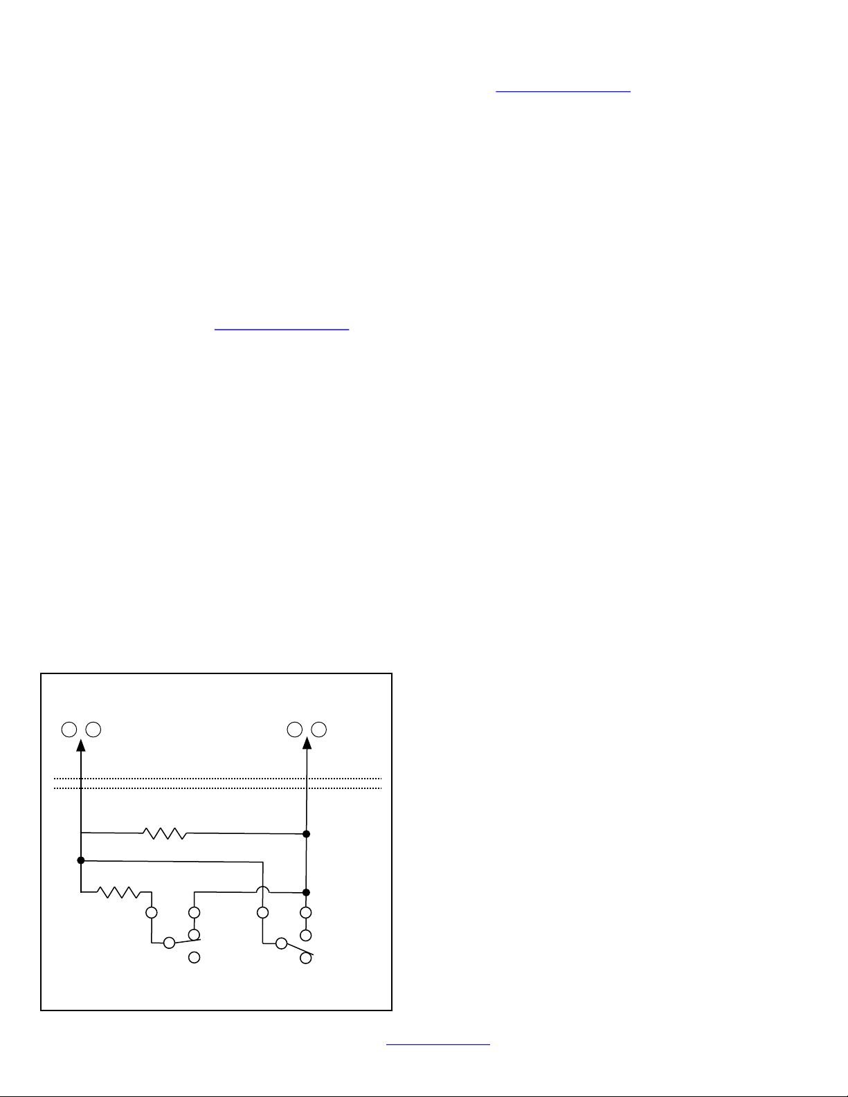
Wire the radio OUT1 relay to a dedicated control panel
zone (input) to annunciate the trouble. Two wiring options
are available:
Activate the trouble with an open by wiring the
EOLR in series with the Common and N/C of the
OUT1 relay;
Activate the trouble with a short by wiring the
EOLR in parallel with the Common and N/O of
the OUT1 relay
The radio must also report this trouble to the central station.
With NAPCO GEMC series control panels, wire the zone as
indicated in the wiring diagrams further in this manual.
Optionally, the FACP trouble relay can be used to trigger a
report to the central station.
Wire the FACP trouble relay to IN2; Common and N/O ter-
minals in parallel with a 10K EOLR. With Gemini C-Series
(GEMC) control panels, we recommend using the Fire Aux
Relay. Program the Fire Aux Relay to activate as a trouble
relay. Wire this relay to the StarLink module IN 2 terminal;
by wiring the EOLR in parallel with Common and N/O of the
OUT1 relay. Note: We recommend using the text
"Radio Trouble" as the Zone Description.
StarLink Radio Supervision
If the two Telco wires (DACT interconnect wiring to the ra-
dio) between the StarLink radio and the control panel are
cut or otherwise disconnected, the control panel must de-
tect and generate a local trouble indication. Program the
control panel for telephone supervision. Program the Star-
Link radio using the Management Center Advanced Fea-
tures screen (at www.NapcoNOC.com) to enable Tip/
Ring Wiring Fault Report. Refer to wiring diagram.
Supervision Time Schedule Considerations
If a status change (alarm trouble, etc.) is transmitted, the
radio supervision timer is restarted.
For example, if a status change is sent, the next regular
supervision transmission will occur at the interval deter-
mined by your rate plan.
Configuration Download / Firmware Updates
Technician on site required.
For Commercial Installations a technician is required to be
STEP 5: SIGNAL VERIFICATION
After triggering channels, use the StarLink radio Signal
Verification to ensure that the StarLink radio Network has
properly received the signals.
Verify Online: To verify that the signals have been
received by the StarLink radio Network online, go to
www.NapcoNOC.com, log in with your Username and
Password, enter your Company ID number and the
StarLink Radio Number, then click Signal Log.
IMPORTANT: Verify that the signals transmitted by t he
StarLink radio have been properly received by your central
station before leaving the premises.
NOTE: This equipment has been tested and found to
comply with the limits for a Class B Unintentional Radiator,
pursuant to Part 15 of the FCC Rules. These limits are
designed to provide reasonable protection against harmful
interference in a residential installation. This equipment
generates, uses, and can radiate radio frequency energy
and, if not installed and used in accordance with the In-
struction Manual, may cause harmful interference to radio
communications. However, there is no guarantee that in-
terference will not occur in a particular installation. If this
equipment does cause harmful interference to radio or tele-
vision reception, which can be determined by turning the
equipment off and on, the user is encouraged to try to cor-
rect the interference by one of more of the following
measures: 1. Reorient or relocate the receiving antenna;
2. Increase the separation between the equipment and re-
ceiver; 3. Connect the equipment into an outlet on a circuit
different from that to which the receiver is connected; 4.
Consult the dealer or an experienced radio/TV technician
for help.
NAPCO GEMINI C-SERIES (GEMC)
CONTROL PANEL PROGRAMMING
To program the central station receiver reporting format,
use PCD-Windows Quickloader download software. Open
the Digital Communications screen, Central Station Re-
ceivers tab, as shown in the following image:
A "Point ID" (also called "Contact ID") receiver format pro-
gramming example:
The radio can transmit to any central station capable of
receiving SIA Contact ID or 4/2 via DACR technology or
the DSC Sur-Gard Model System II or Sur-Gard System V
central station receivers, Bosch D6100IPV6 or Bosch
D6600 Receiver (with ITS-D6686 Ethernet Adapter) via
TCP/IP using standard line security.
Note: A receiver reporting format must be entered for
each telephone number used, but each telephone number
may be assigned a different format.
CAUTION: The installer should always be certain an
area code is programmed into the control panel.
Optional: If you wish the StarLink radio to report a code
and zone number (Contact ID by default) to the central sta-
tion in response to a triggered input event, see the table on

StarLink™ SLE-LTEVI-FIRE & SLE-LTEAI-FIRE Commercial Series Dual-Path Alarm Communicators -- Installation Instructions 7
ble signal shall be sent to Central Station within 5
minutes of failure by the remained active channel.
d. Reliability of the signal shall be achieved by any of the
following:
Signal repetition - multiple transmissions repeating
the same signal
Parity check - a mathematically check sum algorithm
of a digital message that verifies correlation between
transmitted and received message
An equivalent means that provides a certainty of
99.99 percent that the received message is identical
to the transmitted message
e. The maximum duration between the initiation of an
alarm signal at the protected premises, transmission of
the signal, and subsequent display and recording of
the alarm signal at the Central Station shall not exceed
90 seconds
f. A spare Central Station Receiver shall be provided at
the Central Station and shall be able to be switched
into the place of a failed unit within 30 seconds after
detection of failure
g. All applicable requirements of Federal Communica-
tions Commission (FCC) shall be complied with.
3. When used DACT for Central Station communication, two
means of communication are required. The primary
channel shall be telephone line. Cellular or internet com-
munication shall be limited for the secondary means of
communication and comply with 26.6.3 NFPA 72, 2010
edition. Another telephone line also may be used as sec-
ondary mean of communication.
4. The above-referenced equipment shall be used only with
listed fire alarm control panels and devices, with which
the compatibility has been determined by UL Listing Re-
port
5. Only enclosures painted red in color shall be used.
6. Underwriters Laboratories Inc.'s listing requirements and
limitations shall be complied with.
on site during any reprogramming of the radio or control
panel and must perform / re-perform acceptance testing.
To perform a download or update the radio firmware, jump-
er 1 must be removed. UL requires that the jumper be re-
placed after the download is complete. Failure to replace
the jumper would allow downloads to the radio without
a technician on-site.
For Residential installations jumper 1 may be removed to
permit uploading and downloading without a technician on
site, however, the dealer is responsible for ensuring the
system is operating correctly after any downloads or
changes to the system.
NYC Fire Department Requirements
1. All uses, configurations, arrangements and functions, appli-
cations and installations shall comply with the provisions of
New York City Construction Codes, specifically Building
Code Chapter 9 & 1RCNY §3616-04. Further, the installa-
tion shall be in accordance with applicable provisions of
New York City Fire Code, New York City Electrical Code,
manufacturer's installation requirements, and UL Standard
864.
2. When used Dual Path LTE Communicator (IP and Cellular)
for Central Station communication both primary and sec-
ondary channels of communication shall be required and
shall meet the conditions of 4.1 – 4.7. IP communication
shall be used as primary channel of communication with
Central Station and Cellular Communicator shall be used
as the secondary channel of communication or in reverse
order: Cellular Communicator as primary and Internet con-
nection as the secondary channel.
a. Each communication channel shall be monitored for
integrity at intervals not exceeding 24 hours.
b. Failure any channel of communication shall be annunci-
ated at the protected premises within 5 minutes of fail-
ure.
c. When any channel of communication has failed, a trou-

8StarLink™ SLE-LTEVI-FIRE & SLE-LTEAI-FIRE Commercial Series Dual-Path Alarm Communicators -- Installation Instructions
FACP PC BOARD
LOCAL
DOWNLOAD
TELCO
SECONDARY
TELCO
PRIMARY ETHERNET
1
(+)
2
(‒)
POWER PGM3 IN1 IN2 IN3
3
(‒)
4
(+)
5
(+)
6
(‒)
8
(‒)
7
(+)
9
(+)
10
(‒)
12
(‒)
11
(+)
13
EGND 19
N/O
21
N/C
20
C
IN4 IN5 OUT1
22
N/C
24
N/O
23
C
OUT2
Wiring Diagram for Generic FACPs
without TELCO RJ Sockets
Refer to section
"SUPPLYING POWER".
Note: Optionally
connect IN2 to a panel
output used for
identifying Telco line
cut (this is the DACT
interconnect wiring to
the radio).
SECONDARY TELCO PRIMARY TELCO
IN PHONES IN PHONES
RJ31X
RING TIP
(+) (‒)
(STARLINK RADIO HOUSING)
StarLink Radio Terminals
PC Board: All connections are power limited except AC Mains and battery terminals.
JP1
Shunt JP1
on top 2 pins
Optional: Use 12 or
24VDC Listed regulated
power supply*.
Note: Common radio
ground and FACP
ground.
GREEN
RED
(CONTROL PANEL HOUSING)
10kΩ
10kΩ
10kΩ
DO NOT
USE EOLR
GREEN
RED
WIRE DIRECTLY TO CONTROL
PANEL (USE FOR SHORTER DISTANCES)
OPTIONAL: WIRE TO RJ31X
(USE FOR LONGER DISTANCES)
RJ31X
RING TIP
GREEN
RED
WIRE DIRECTLY TO CONTROL
PANEL (USE FOR SHORTER DISTANCES)
OPTIONAL: WIRE TO RJ31X
(USE FOR LONGER DISTANCES)
GREEN
RED
10kΩ
10kΩ
To FACP Zone
Dedicated to
Radio Trouble*
EOLR
JP2
Remove JP2 to
enable TELCO2
trouble on
Communicator trouble
*Not required if JP2 shunt is removed and FACP monitors TELCO 2.
AUX / REMOTE
FIRE PWR
J7
J7: Remove shunt to
disable 10K EOLR
across pins 1 and 8 of
primary TELCO input.
Do not remove if "Tip/
Ring Wiring Fault
Report" is enabled.

StarLink™ SLE-LTEVI-FIRE & SLE-LTEAI-FIRE Commercial Series Dual-Path Alarm Communicators -- Installation Instructions 9
FACP PC BOARD
LOCAL
DOWNLOAD
TELCO
SECONDARY
TELCO
PRIMARY ETHERNET
1
(+)
2
(‒)
POWER PGM3 IN1 IN2 IN3
3
(‒)
4
(+)
5
(+)
6
(‒)
8
(‒)
7
(+)
9
(+)
10
(‒)
12
(‒)
11
(+)
13
EGND 19
N/O
21
N/C
20
C
IN4 IN5 OUT1
22
N/C
24
N/O
23
C
OUT2
Wiring Diagram for Generic FACPs
with TELCO RJ Sockets
Refer to section
"SUPPLYING POWER".
Note: Optionally
connect IN2 to a panel
output used for
identifying Telco line cut
(this is the DACT
interconnect wiring to the
radio).
(+) (‒)
(STARLINK RADIO HOUSING)
StarLink Radio Terminals
PC Board: All connections are power limited except AC Mains and battery terminals.
Optional: Use 12 or
24VDC Listed regulated
power supply*.
Note: Common radio
ground and FACP
ground.
(CONTROL PANEL HOUSING)
TELCO RJ
SOCKET
(PRIMARY)
10kΩ
10kΩ
10kΩ
TELCO RJ
SOCKET
(SECONDARY)
10kΩ
To FACP Zone
Dedicated to
Radio Trouble*
EOLR
Requires all 8 wires in
the RJ-45 cable
JP1
Shunt JP1
on top 2 pins
JP2
Remove JP2 to
enable TELCO2
trouble on
Communicator trouble
*Not required if JP2 shunt is removed and FACP monitors TELCO 2.
AUX / REMOTE
FIRE PWR
J7
J7: Remove shunt to
disable 10K EOLR
across pins 1 and 8 of
primary TELCO input.
Do not remove if "Tip/
Ring Wiring Fault
Report" is enabled.

10 StarLink™ SLE-LTEVI-FIRE & SLE-LTEAI-FIRE Commercial Series Dual-Path Alarm Communicators -- Installation Instructions
CONTROL PANEL PC BOARD
LOCAL
DOWNLOAD
TELCO
SECONDARY
TELCO
PRIMARY ETHERNET
1
(+)
2
(‒)
POWER PGM3 IN1 IN2 IN3
3
(‒)
4
(+)
5
(+)
6
(‒)
8
(‒)
7
(+)
9
(+)
10
(‒)
12
(‒)
11
(+)
13
EGND 19
N/O
21
N/C
20
C
IN4 IN5 OUT1
22
N/C
24
N/O
23
C
OUT2
(STARLINK RADIO HOUSING)
StarLink Radio Terminals
PC Board: All connections are power limited except AC Mains and battery terminals.
JP1
Shunt JP1
on top 2 pins
Wiring Diagram for FACP Relay Trigger Input Reporting
Refer to section "SUPPLYING POWER".
NC
(+) (‒)
NORMALLY
ENERGIZED
FIRE TROUBLE
RELAY
C NO
10kΩ
Aux Power:
Regulated 12/24VDC or
optionally use 12 or
24VDC regulated Listed
power supply*. Note:
Common radio ground and
FACP ground.
(CONTROL PANEL HOUSING)
FIRE ALARM
RELAY
SUPERVISORY
ALARM
RELAY
WATER FLOW
ALARM
RELAY
10kΩ 10kΩ 10kΩ
NO
C NC NO
C NC NO
C NC
EOLR
AUX
INPUT
TROUBLE
INPUT
EOLR
AUX / REMOTE
FIRE PWR
J7
J7: Remove shunt to
disable 10K EOLR
across pins 1 and 8 of
primary TELCO input.
Do not remove if "Tip/
Ring Wiring Fault
Report" is enabled.

StarLink™ SLE-LTEVI-FIRE & SLE-LTEAI-FIRE Commercial Series Dual-Path Alarm Communicators -- Installation Instructions 11
(STARLINK RADIO HOUSING)
StarLink Radio Terminals
LOCAL
DOWNLOAD
TELCO
SECONDARY
TELCO
PRIMARY ETHERNET
1
(+)
2
(‒)
POWER PGM3 IN1 IN2 IN3
3
(‒)
4
(+)
5
(+)
6
(‒)
8
(‒)
7
(+)
9
(+)
10
(‒)
12
(‒)
11
(+)
13
EGND 19
N/O
21
N/C
20
C
IN4 IN5 OUT1
22
N/C
24
N/O
23
C
OUT2
Wiring Diagram for GEMC-32, GEMC-96,
GEMC-128 and GEMC-255 Control Panels
(CONTROL PANEL HOUSING)
**
GEMC Control Panel
PC Board
Refer to section "SUPPLYING POWER".
*Not required if JP2 shunt is removed and
FACP monitors TELCO 2.
**Program only TELCO 1 supervision.
Note: Connect IN2 to a panel output
used for identifying Telco line cut (this is
the DACT interconnect wiring to the radio).
PC Board: All connections are power limited except AC Mains and battery terminals.
Or use a
12V/24V UL
Listed
monitored
power supply*
(Optional, for remote
communication)
OPTIONAL
MONITOR
ZONE
TO MONITOR ZONE
(+) FACP ZONE
DEDICATED TO
RADIO TROUBLE*
EOLR
EOLR
JP1
Shunt
JP1
on top
2 pins
Requires all 8 wires in
the RJ-45 cable
JP2
Remove JP2 to
enable TELCO2
trouble on
Communicator trouble
AUX /
REMOTE
FIRE PWR
J7
J7: Remove shunt to
disable 10K EOLR
across pins 1 and 8 of
primary TELCO input.
Do not remove if "Tip/
Ring Wiring Fault
Report" is enabled.

12 StarLink™ SLE-LTEVI-FIRE & SLE-LTEAI-FIRE Commercial Series Dual-Path Alarm Communicators -- Installation Instructions
This page intentionally left blank.

StarLink™ SLE-LTEVI-FIRE & SLE-LTEAI-FIRE Commercial Series Dual-Path Alarm Communicators -- Installation Instructions 13
Housing Template (1:1 Scale)
Three-Gang Mounting
Double-Gang

14 StarLink™ SLE-LTEVI-FIRE & SLE-LTEAI-FIRE Commercial Series Dual-Path Alarm Communicators -- Installation Instructions
This page intentionally left blank.

StarLink™ SLE-LTEVI-FIRE & SLE-LTEAI-FIRE Commercial Series Dual-Path Alarm Communicators -- Installation Instructions 15
Name Format Type Handshake Frequency Speed
Ademco Slow 4/2 1400 Hz or 2300Hz 10pps
Ademco Slow 4/2 checksum 1400 Hz or 2300Hz 10pps
Radionics Slow 4/2 2300Hz 10pps
Radionics Slow 4/2 checksum 2300Hz 10pps
Silent Knight Fast 4/2 1400 Hz or 2300Hz 20pps
Silent Knight Fast 4/2 checksum 1400 Hz or 2300Hz 20pps
Radionics Fast 4/2 2300Hz 40pps
Radionics Fast 4/2 checksum 2300Hz 40pps
Universal High Speed 4/2 1400 Hz or 2300Hz 40pps
Universal High Speed 4/2 checksum 1400 Hz or 2300Hz 40pps
4/2 Pulse Dialing
Format
Compatibility
Note: The SLE Series Radios are
compatible with any Listed 4/2
Receiver such as the Ademco 685.
REN = 0. The Ringer Equivalence Number (REN) indicates the maximum number
of devices allowed to be connected to a telephone interface. The termination of an
interface may consist of any combination of devices subject only to the requirement that
the sum of the RENs of all the devices not exceed five (5).
To terminate more than two conductors or
conductors of different wire sizes to a terminal,
use the "pigtail" type wiring method as shown at
right. Use insulated wire for the pigtail, and firmly
secure the conductors to the pigtail using an ap-
propriate wire nut or crimp connector for the num-
ber and gauge of conductors used.
IM P OR TAN T W IR IN G M E T H O DS
Incorrect
Correct -- Use pigtail and wire nut / crimp connector
PIGTAIL
WIRE NUT OR
CRIMP
CONNECTOR
PIGTAIL
For single-conductor terminal
blocks (like the type shown at
left), to terminate more than one
conductor to a terminal, use the
wiring methods shown at right:
WIRE NUT OR
CRIMP
CONNECTOR
PIGTAIL
Correct -- Single incoming and/or pigtail with wire nut / crimp connectors
In
For "barrier" type terminal
blocks (like the type shown at
left), to terminate two conductors
to a terminal, use the wiring meth-
ods shown at right: Correct -- Separate incoming and outgoing conductors
In Out
Incorrect
Incorrect
In Out
Alternate Telco Line to Alarm Panel Supervision
The following wiring and programming method allows an existing FACP to use its two telephone connections
(primary and secondary) for supervision and central station reporting through the StarLink SLE-LTEVI-FIRE radio.
By removing the JP2 shunt and enabling the feature "Tip/Ring Wiring Fault Report", when any radio trouble is
detected, the StarLink radio will remove voltage from the secondary telephone output, triggering the FACP to locally
annunciate the Telco trouble and report the trouble to the central station. Note: Some FACPs require J7 shunt to be
removed for Primary Phone line to restore correctly.

16 StarLink™ SLE-LTEVI-FIRE & SLE-LTEAI-FIRE Commercial Series Dual-Path Alarm Communicators -- Installation Instructions
NAPCO SECURITY TECHNOLOGIES, INC.
(NAPCO) warrants its products to be free from
manufacturing defects in materials and workmanship
for thirty-six months following the date of
manufacture. NAPCO will, within said period, at its
option, repair or replace any product failing to
operate correctly without charge to the original
purchaser or user.
This warranty shall not apply to any equipment,
or any part thereof, which has been repaired by
others, improperly installed, improperly used,
abused, altered, damaged, subjected to acts of God,
or on which any serial numbers have been altered,
defaced or removed. Seller will not be responsible
for any dismantling or reinstallation charges.
THERE ARE NO WARRANTIES, EXPRESS OR
IMPLIED, WHICH EXTEND BEYOND THE
DESCRIPTION ON THE FACE HEREOF. THERE
IS NO EXPRESS OR IMPLIED WARRANTY OF
MERCHANTABILITY OR A WARRANTY OF
FITNESS FOR A PARTICULAR PURPOSE.
ADDITIONALLY, THIS WARRANTY IS IN LIEU OF
ALL OTHER OBLIGATIONS OR LIABILITIES ON
THE PART OF NAPCO.
Any action for breach of warranty, including but
not limited to any implied warranty of
merchantability, must be brought within the six
months following the end of the warranty period. IN
NO CASE SHALL NAPCO BE LIABLE TO ANYONE
FOR ANY CONSEQUENTIAL OR INCIDENTAL
DAMAGES FOR BREACH OF THIS OR ANY
OTHER WARRANTY, EXPRESS OR IMPLIED,
EVEN IF THE LOSS OR DAMAGE IS CAUSED BY
THE SELLER'S OWN NEGLIGENCE OR FAULT.
In case of defect, contact the security
professional who installed and maintains your
security system. In order to exercise the warranty,
the product must be returned by the security
professional, shipping costs prepaid and insured to
NAPCO. After repair or replacement, NAPCO
assumes the cost of returning products under
warranty. NAPCO shall have no obligation under this
warranty, or otherwise, if the product has been
repaired by others, improperly installed, improperly
used, abused, altered, damaged, subjected to
accident, nuisance, flood, fire or acts of God, or on
which any serial numbers have been altered,
defaced or removed. NAPCO will not be responsible
for any dismantling, reassembly or reinstallation
charges.
This warranty contains the entire warranty. It is
the sole warranty and any prior agreements or
representations, whether oral or written, are either
merged herein or are expressly cancelled. NAPCO
neither assumes, nor authorizes any other person
purporting to act on its behalf to modify, to change,
or to assume for it, any other warranty or liability
concerning its products.
In no event shall NAPCO be liable for an amount
in excess of NAPCO's original selling price of the
product, for any loss or damage, whether direct,
indirect, incidental, consequential, or otherwise
arising out of any failure of the product. Seller's
warranty, as hereinabove set forth, shall not be
enlarged, diminished or affected by and no
obligation or liability shall arise or grow out of
Seller's rendering of technical advice or service in
connection with Buyer's order of the goods furnished
hereunder.
NAPCO RECOMMENDS THAT THE ENTIRE
SYSTEM BE COMPLETELY TESTED WEEKLY.
Warning: Despite frequent testing, and due to,
but not limited to, any or all of the following; criminal
tampering, electrical or communications disruption, it
is possible for the system to fail to perform as
expected. NAPCO does not represent that the
product/system may not be compromised or
circumvented; or that the product or system will
prevent any personal injury or property loss by
burglary, robbery, fire or otherwise; nor that the
product or system will in all cases provide adequate
warning or protection. A properly installed and
maintained alarm may only reduce risk of burglary,
robbery, fire or otherwise but it is not insurance or a
guarantee that these events will not occur.
CONSEQUENTLY, SELLER SHALL HAVE NO
LIABILITY FOR ANY PERSONAL INJURY,
PROPERTY DAMAGE, OR OTHER LOSS BASED
ON A CLAIM THE PRODUCT FAILED TO GIVE
WARNING. Therefore, the installer should in turn
advise the consumer to take any and all precautions
for his or her safety including, but not limited to,
fleeing the premises and calling police or fire
department, in order to mitigate the possibilities of
harm and/or damage.
NAPCO is not an insurer of either the property or
safety of the user's family or employees, and limits
its liability for any loss or damage including
incidental or consequential damages to NAPCO's
original selling price of the product regardless of the
cause of such loss or damage.
Some states do not allow limitations on how long
an implied warranty lasts or do not allow the
exclusion or limitation of incidental or consequential
damages, or differentiate in their treatment of
limitations of liability for ordinary or gross
negligence, so the above limitations or exclusions
may not apply to you. This Warranty gives you
specific legal rights and you may also have other
rights which vary from state to state.
NAPCO LIMITED WARRANTY
Other manuals for StarLink SLE-LTEVI-FIRE
1
This manual suits for next models
1
Table of contents
Other NAPCO Cell Phone manuals

NAPCO
NAPCO StarLink SLE-LTEVI-FIRE User manual

NAPCO
NAPCO StarLink SLE Series User manual

NAPCO
NAPCO StarLink SLE Series User manual

NAPCO
NAPCO Gemini GEM-P816 User manual

NAPCO
NAPCO Gemini GEM-P1632 Installation manual

NAPCO
NAPCO Gemini GEM-P1632 Installation manual

NAPCO
NAPCO StarLink SLE-LTEV-SS User manual

NAPCO
NAPCO StarLink SLE-LTEVI Series User manual

NAPCO
NAPCO StarLink SLE-LTE Commercial Series User manual

NAPCO
NAPCO StarLink SLE User manual