NAPCO StarLink SLE-LTEVI Series User manual

StarLink™SLE Commercial LTEVI & LTEAI Series Dual-Path Alarm Communicators -- Installation Instructions 1
ADDITIONAL COMPONENTS
In addition to the models listed above, the following sub-
assemblies are available:
SLE-ULPS-R - Power Supply. Required for installations
where the control panel cannot provide the Auxiliary
power required to operate the StarLink radio. Uses a
standard 4AH / 12V minimum (7AH maximum, required
with optional Wi-Fi Module) rechargeable battery to pro-
vide radio standby power. Requires connection to either
the model NAPCO TRF12/T123 (16.5V / 20VA) external
plug-in transformer or the chassis-mounted 16.5VAC /
20VA transformer affixed inside the housing (see wiring
diagrams further in this manual). Note: For models
without the SLE-ULPS-R, connect the radio terminals 1
and 2 to the control panel Aux Power terminals
(observing polarity).
SLE-WIFI-MODULE - Allows your Napco StarLink™device
to connect to the Internet by means of a wireless (Wi-Fi)
link, eliminating a wired Ethernet cable connection.
Note: 7AH battery required when using the SLE-
WIFI-MODULE. For more information, see WI2191.
SLE-DLCBL - Download Cable, 6 feet
SLE-ANTEXT30 - Extended antenna with 30 feet of cable
SLE-ANTEXT50 - Extended antenna with 50 feet of cable
SLE-ANTEXT75 - Extended antenna with 75 feet of cable
SLE-ANTEXT100 - Extended antenna with 100 feet of cable
(Any suitable external cellular antenna is permitted by
UL). Always follow the manufacturer's installation in-
structions. Note: Antennas are not Listed by UL.
GEM-Tamperkit - Tamper switches and screws to protect
metal housing (see page 14).
SPECIFICATIONS
The following specifications apply to all StarLink radio mod-
els unless otherwise stated:
Electrical Ratings for 120VAC, 60Hz
For Models with Power Supply
Input Voltage: 120VAC nominal
StarLink™ SLE Commercial
LTEVI & LTEAI Series
Dual-Path Alarm Communicators
INSTALLATION INSTRUCTIONS
WI2327ELF 11/19
333 Bayview Avenue, Amityville, New York 11701
For Sales and Repairs, (800) 645-9445
For Technical Service, (800) 645-9440 or visit us at
http://tech.napcosecurity.com/
(Note: Technical Service is for security professionals only)
Publicly traded on NASDAQ Symbol: NSSC
© NAPCO 2019
INTRODUCTION
The StarLink™LTE Series Dual-Path Commercial / Resi-
dential Fire alarm capture radio IP communicators are fully
supervised, wireless digital two-way subscriber units. All
models are compatible with most 12/24VDC alarm control
panels (always adhere to the documentation provided by
the control panel manufacturer). These communicators are
for use as the primary means of communication with the
central station and do not have backup mode capability.
No POTS (Telco Line) connection permitted. See WI2140
for programming information.
The following models are available:
SLE-LTEVI-CFBPS & SLE-LTEAI-CFBPS: Commercial /
Residential Fire LTE Radio-TCP/IP Communicators in
red metal housing with SLE-ULPS-R power supply and
16.5V / 20VA transformer mounted inside housing
SLE-LTEVI-CFB & SLE-LTEAI-CFB: Commercial / Resi-
dential Fire LTE Radio-TCP/IP Communicators in red
metal housing. Powered directly from control panel (no
power supply, no transformer, rated nominal 12/24VDC
input)
The following features are included with models that in-
clude a SLE-ULPS-R power supply:
Power limited output to the StarLink radio PC board 12V
input terminals
Battery connection red and black flying leads
Monitored battery charging and Active battery test circuits
StarLink radio trouble input (from StarLink radio PC
board PGM1 terminal to detect StarLink radio trouble)
Requires a sealed lead acid min 4AH / max 7AH battery
for minimum 24-hour standby time (max charge current
200mA).
Trouble relay output (C, N/O and N/C terminals) to
wire to a panel zone dedicated to "Radio Trouble" (dry
contacts). Remove jumper "J2" isolate relay OUT1
common from ground
Green AC ON LED visible from the exterior housing
Yellow TROUBLE LED "D4" on PC board. Flashes sig-
nify:
One flash: AC fail / brownout
Two flashes: Low battery
Three flashes: Charging circuit trouble
Four flashes: StarLink radio trouble
The housing-mounted transformer (when provided) is
mounted inside its own housing compartment with a re-
placeable UL Listed .5A fast blow primary fuse. 120VAC
connections are to be made by a licensed electrician using
suitable connectors, in accordance with N.E.C. and local
code requirements.
AGENCY LISTINGS
UL 864 Standard For Control Units and Accessories For Fire
Alarm Systems, 10th Edition
UL 1610 Standard For Central-Station Burglar-Alarm Units
UL 985 Standard For Household Fire Warning System Units
UL 1023 Standard For Household Burglar-Alarm System Units
UL 1076 APOU Proprietary Alarm Systems
UL 365 APAW Police Connect

2 StarLink™SLE Commercial LTEVI & LTEAI Series Dual-Path Alarm Communicators -- Installation Instructions
Input Current: 200mA maximum
Maximum Charging Current: 200mA
Electrical Ratings for +12V / 24V
For Models without Power Supply†
Input Voltage: 10-25VDC regulated (power-limited out-
put from Listed control panel).
Input Current:
10VDC standby: 162mA
12VDC standby: 125mA
15VDC standby: 110mA
24VDC standby: 100mA (Commercial Fire models)
25VDC standby: 100mA (Commercial Fire models)
Wi-Fi Module: (Optional) Add 40mA to the above.
(With peak RF transmission current of 325mA).
Electrical Ratings for the IN 1 Fire Input:
Input Voltage: 9-25VDC.
Maximum Input Current: Up to 2mA from FACP NAC
circuit
Electrical Ratings for IN 2, IN 3, IN 4, and IN 5:
(Inputs IN 2, IN 3, IN 4, and IN 5 are Class B)
Maximum Loop Voltage: 25VDC.
Maximum Loop Current: 1.2mA
End of Line Resistor (EOLR) Value: 10K (2 req'd)
Electrical Ratings for PGM3 Output:
Open Collector Output: Maximum Voltage 3V when
active; 25V maximum when not active.
Maximum PGM Sink Current: 50mA (up to 15VDC),
25mA (15.1VDC - 25VDC)
Physical (W x H x D)
Metal Housing: 11½ x 9½ x 3½" (29.2 x 24.1 x 8.9cm)
Mounting: Metal housing includes two keyhole slots for
wall mounting (see measurements on page 7)
Environmental
Operating Temperature: 0°C - 49°C (32°F - 120°F)
Humidity: Maximum 93% Non-Condensing
Indoor / dry location use only
TERMINAL DESCRIPTIONS
Configure all inputs and outputs using the Management
Center screen (located at www.NapcoNOC.com). Located
at the bottom of the StarLink radio PC board, the 17 termi-
nals are described as follows:
TB1: PWR (+10 - 25VDC)
(Refer to section "STEP 4: APPLY POWER")
TB2: PWR GND (–)
(Refer to section "STEP 4: APPLY POWER")
TB3: PGM3 (–): Open collector output. PGM3 is normally
on (active low). When it is triggered (for example, a
trouble is detected) it becomes open collector/high.
To have a zone dedicated to an StarLink radio trou-
ble, insert one side of the end of line resistor into this
PGM3 terminal, and wire the other side of the resis-
tor to the positive terminal of the zone.
TB4: IN 1 (+): Smart Channel input. Active high input
for wiring to the control panel bell output. When this
input detects a pulsing temporal 3 high, it sends a
Fire alarm; a pulsing temporal 4 (CO Alarm), a CO
alarm is sent. When used, these conductors must
be run in conduit (max 20 feet for Commercial Fire,
and 3 feet for Residential Fire). For this input to re-
port to a central station, the StarLink radio must be
configured with the central station telephone number
and correct reporting formats and codes. For more
information, see WI2140 located at
www.NapcoNOC.com.
TB5: IN 2 (+): Fire Trouble input**. Wire to FACP trou-
ble relay N/O with parallel 10K EOLR at FACP.
Note: Inputs IN 2, IN 3, IN 4 and IN 5 can be su-
pervised end-of-line resistor inputs that can be trig-
gered with N/O or N/C relay contacts.
TB6: IN 2 (–): See TB5, above.
TB7: IN 3 (+): Fire Alarm input**. Wire to FACP Fire
Alarm relay N/O with parallel 10K EOLR at FACP.
TB8: IN 3 (–): See TB5 and TB7, above.
Secondary Telephone: RJ-45 socket for FACP DACT
connection.
Primary Telephone: RJ-45 socket for FACP DACT con-
nection.
TB9: IN 4 (+): Supervisory Alarm input**. Wire to
FACP Supervisory relay N/O with parallel 10K EOLR
at FACP.
TB10: IN 4 (–): See TB5 and TB9, above.
TB11: IN 5 (+): Water Flow Alarm input**. Wire to FACP
Water Flow relay with parallel 10K EOLR at FACP.
TB12: IN 5 (–): See TB5 and TB11, above.
TB13: GND: Earth ground terminal.
Ethernet: Connect the SLE Dual-Path radio communica-
tor to your broadband modem, router or switch.
Note: The cable modem/router and switch (if any)
at the premises requires standby power, therefore a
UL 1481 / UL 864 or UL Listed ITE (Information
Technology Equipment) UPS must be used at the
premises to power these devices for a minimum of
24 hours.
TB19: N/O OUT1: Normally open. Dry contact Form C
†For Commercial Fire installations, a UL Listed Fire Alarm regulated power supply or FACP regulated auxiliary output is required.
*Reverse polarity / energized state.
**Factory programmed options; may be changed at the NOC website (www.NapcoNOC.com).
Supervised Fire Input Wiring Option
10K
10K
CC
N/O
Alarm
N/O
TBL*
To StarLink
Terminals
IN2 (TB5)
-or-
IN3 (TB7)
Radio GND
(TB6 and
TB88)
The EOLR must be installed and located within the control panel housing.
(Radio)
(Alarm Panel)
5 7
-or-
N/C
6 8
-or-
N/C

StarLink™SLE Commercial LTEVI & LTEAI Series Dual-Path Alarm Communicators -- Installation Instructions 3
When processing an alarm, this LED will blink variably
during each part of the process (dialing, handshaking,
data transmission, etc.).
RED TROUBLE LED
Labeled "D5", this LED is located at the bottom right of
the PC board. Operation is as follows:
1 Blink: Low Aux Power input voltage
2 Blinks: Battery trouble
3 Blinks: Alarm report Failed to Communicate (will
restore only when the radio path is restored)
4 Blinks: RF trouble (antenna connection or cellu-
lar registration)
5 Blinks: Radio poll or check-in failure (radio and/or
Ethernet). Either or both paths will trigger the trouble,
but for the trouble to clear, unit requires both IP and
radio polling/checkins to be operational
6 Blinks: Unit disabled (reporting or control panel
downloading not allowed)
7 Blinks: Unit was shutdown and has no function-
ality; requires a restart (full power down and full power
up sequence) to restore operation
8 Blinks: Telco Line Cut
RED DIAGNOSTIC LED
Labeled "D7", this LED is located in the middle of the PC
board. One blink indicates a weak or non-existent signal
from the network (green LED is off). If this red LED is
blinking in any other manner, contact technical support.
GREEN IP NETWORK CONNECTION LED
Labeled "D14" (or DS14), this LED is located to the right
of the ETHERNET socket on the PC board. Operation is
as follows:
Off = No network cable detected
Fast Flash = No IP connection (Occurs just after pow-
er on, while trying to obtain a IP address)
Slow Flash = Normal IP network operation
1 Blink: Static IP
2 Blinks: DHCP
3 Blinks: Auto IP (If unable to acquire DHCP ad-
dress, then after 5 minutes it will convert to Auto IP
relay. Add shunt to lower two pins of JP1 for wet
contacts.
TB20: C OUT1: Common. Dry contact Form C relay.
Add shunt to lower two pins of JP1 for wet contacts
(connects relay Common to system ground). Relay
rated 30V AC/DC, 500mA.
TB21: N/C OUT1: Normally closed. Dry contact Form
C relay. Add shunt to lower two pins of JP1 for wet
contacts.
TB22: N/O OUT2: Normally open. Dry contact Form C
relay.
TB23: C OUT2: Common. Dry contact Form C relay.
Relay rated 30V AC/DC, 500mA.
TB24: N/C OUT2: Normally closed. Dry contact Form
C relay.
LED DESCRIPTIONS
The PC board contains several LED's, as follows:
GREEN RF SIGNAL STRENGTH LED
Labeled "D3", this LED is located at the lower right corner
of the PC board.
Every 30 seconds, the StarLink radio receiver section
turns on and listens to the cell tower. Depending on the
signal strength detected, it will blink the Signal Strength
LED from 1 to 5 times, providing a signal strength indica-
tor that is updated constantly and is always displayed.
Green LED Operation
Signal strength (as received by the radio) is displayed by
this LED blinking 1 to 5 times at a constant rate (with a
short delay between blink cycles). Acceptable power lev-
el is greater than or equal to 2 blinks.
YELLOW OPERATIONAL STATUS LED
Labeled "D4", this LED is located at the bottom right of
the PC board. Operation is as follows:
Normal Standby Condition:
Blinks on momentarily every 10 seconds: Unit is in
standby waiting for an alarm to report.
Processing Alarm Conditions:
FIRE PROGRAMMING OPTION PERMITTED IN
UL864? (Y/N) AVAILABLE SETTINGS REQUIRED UL 864 SETTINGS
Unattended Remote Downloading No Enable / Disable
Disabled (Jumper 1 installed). Also required for Commercial installations. Note:
See page 7 "Configuration Download / Firmware Updates" for jumper instruc-
tions.
IN2 and IN3 Unsupervised Yes Supervised / Unsupervised
Unsupervised using conduit within 20 feet of FACP (default). If not using conduit,
install Jumpers 4 and 5 and EOL Resistors. Inputs 2 an 3 can be unsupervised
with jumpers 4 and 5 removed; IN4 and IN5 always require EOLR
7 Day Supervision, Radio to NOC No
200 seconds, 5 minutes, 6
minutes, 60 minutes, 6
hours, 7 days
200 seconds, 5 minutes, 60 minutes. 6 Hours permitted in Commercial Fire UL
864 with Dual Path enabled.
Trouble on Radio or IP Path
(Annunciate / Report) Yes Either Path or Both Paths Either Path (annunciation and report of trouble)
NOTICE TO AUTHORITIES HAVING JURISDICTION, USERS, INSTALLERS,
DEALERS, AND OTHER AFFECTED PARTIES
Wi-Fi Module Yes Enable / Disable May be enabled as a primary reporting path for Fire

4 StarLink™SLE Commercial LTEVI & LTEAI Series Dual-Path Alarm Communicators -- Installation Instructions
RED IP NETWORK TROUBLES LED
Labeled "D16" (or DS16), this LED is located to the right
of the ETHERNET socket on the PC board. Operation is
as follows:
Off = No troubles
Fast Flash = No IP connection (occurs just after pow-
er on while trying to obtain a DHCP address)
Slow Flashing:
1 Blink: No network cable detected
2 Blinks: No access to the Internet (mutually exclu-
sive with no network cable)
3 Blinks: Ethernet failed to communicate
4 Blinks: Ethernet poll / checkin failure
5 Blinks: Wi-Fi is enabled, but SLE-WIFI-MODULE is
not detected
6 Blinks: Wi-Fi no access to the Internet
7 Blinks: Wi-Fi failed to communicate
8 Blinks: Wi-Fi poll / checkin failure
9 Blinks: Wi-Fi serial data error or no serial data re-
sponse
10 Blinks: Wi-Fi Security/Authentication failed
YELLOW IP NETWORK STATE LED
Labeled "D15" (or DS15), this LED is located to the right
of the ETHERNET socket on the PC board. Operation is
as follows:
Off = No power
Steady with 1 quick blink off every 1.7 seconds when
reporting signal to NOC
Steady with 2 quick blinks off every 1.7 seconds
when downloading to control panel or the module
Slow Flashing:
1 Blink: Ethernet Available
2 Blinks: Wi-Fi Station Mode (normal operation)
SUPPLYING POWER
Control panels can provide power through their Auxiliary
Power terminals if the available standby current is reduced
by the SLE standby power (refer to Electrical Ratings for
+12V / 24V for models without Power Supply on page 1).
When there is insufficient standby current due to the appli-
cation (such as when 24-hour standby time is required for
Fire or CO), the SLE-ULPS-R Charger Module accessory
must be used to charge an additional battery and to supply
the power for the StarLink radio. See WI2131.
Note: The cable modem/router and switch (if any) at the
premises requires standby power, therefore a UL 1481 or
UL 864 Listed UPS must be used at the premises to power
these devices for 24 hours (unless an engine driven genera-
tor is provided on the premises, then only 4 hours of UPS
backup are required).
JUMPER DESCRIPTIONS
Jumper block labeled "X5"; from top to bottom, as detailed
in the table below. Note: Contact ID is always available in
response to a Contact ID handshake.
The SLE Series Dual-Path radios are compatible with 4/2
Pulse Dialing formats with 10pps, 20pps, and 40pps with
and without checksum, either 1400Hz or 2300Hz hand-
shake / kissoff. See page 6 for table of formats.
Refer to WI2140 for selecting the required handshake /
kissoff frequency in the NOC (www.NapcoNOC.com) setup
screens (as required by the control panel).
PRIMARY REPORTING
The StarLink radio can function as a primary wireless IP
communicator, in cases where there are no telephone
lines present, when connected directly to the control panel
Telco terminals. For primary reporting, do NOT install
jumper 3 in terminal block "X5". These communicators
are for use as the primary means of communication with
the central station and do not have backup mode capabil-
ity.
NETWORK COVERAGE
The StarLink radio constantly supervises the cell network
coverage. When the StarLink radio is configured for pri-
mary reporting, and the StarLink radio detects a loss in
network coverage, the StarLink radio must be configured
to prompt the control panel to announce a Telco Line Cut
failure trouble using the Management Center screen
(located at www.NapcoNOC.com).
INSTALLATION STEPS
STEP 1: ACCOUNT REGISTRATION
Create a new account and register specific StarLink radio
modules at www.NapcoComNet.com. Accounts and mod-
Jumper Block "X5" Options
Jumper block labeled "X5" contains 5 jumper terminals; from top (labeled
"1") to bottom (labeled "5") as follows:
Jumper ON Jumper
Number Jumper OFF
Tech on site must temporarily
remove to download 1 Not permitted by UL 864
4/2 with Checksum Pulse Format* 2 4/2 Pulse Format*
Supervised inputs IN3 and IN2,
respectively.
EOLR(s) required, see page 2
4 and 5
Not permitted by UL 864
(UL 864 permits use of conduit
within 20 feet of FACP in lieu of
Supervision)
*See table "NOTICE TO AUTHORITIES HAVING JURISDICTION..." on page 3.
LED LOCATIONS
D4 D3 D5
RED DIAGNOSTIC LED (Labeled "D7")
YELLOW OPERATIONAL STATUS LED (Labeled "D4")
GREEN RF SIGNAL STRENGTH LED (Labeled "D3")
RED TROUBLE LED (Labeled "D5")

StarLink™SLE Commercial LTEVI & LTEAI Series Dual-Path Alarm Communicators -- Installation Instructions 5
(Place JP1 shunt on bottom two pins)
Wiring Methods
Strip wire carefully to avoid exposed conductors after
installation, etc.
Use UL Listed wire, ensuring that all conductors are to
be insulated for the maximum voltage of any conductor
in the enclosure
All wiring methods must be performed in accordance
with NFPA 70, Articles 725, and 800
STEP 4: APPLY POWER
Attach antennas before applying power !
Apply 12/24VDC to terminals 1 and 2. (For models
without the charger board SLE-ULPS-R). For models
with the SLE-ULPS-R, apply power to the unit.
STEP 5: SIGNAL VERIFICATION
Verify Online: To verify that the signals have been
received by the StarLink radio Network online, go to
www.NapcoNOC.com, log in with your Username and
Password, enter your Company ID number and the
StarLink Radio Number, then click Signal Log.
IMPORTANT: Verify that the signals transmitted by the
StarLink radio have been properly received by your central
station before leaving the premises.
NAPCO GEMINI C-SERIES (GEMC)
CONTROL PANEL PROGRAMMING
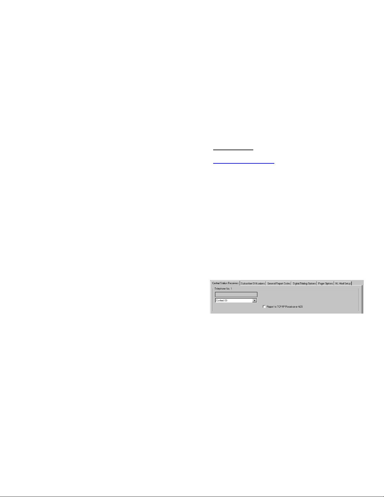
To program the central station receiver reporting format,
use PCD-Windows Quickloader download software. Open
the Digital Communications screen, Central Station Re-
ceivers tab, as shown in the following image:
A "Point ID" (also called "Contact ID") receiver format pro-
gramming example is shown:
The radio can transmit to any central station capable of
receiving SIA Contact ID or 4/2 via DACR technology or
the DSC Sur-Gard Model System II or Sur-Gard System V
central station receivers, Bosch D6100IPV6 or Bosch
D6600 Receiver (with ITS-D6686 Ethernet Adapter) via
TCP/IP using standard line security.
Note: A receiver reporting format must be entered for
each telephone number used, but each telephone number
may be assigned a different format.
Note: UL Listed for UL 1076 APOU Proprietary Alarm
Systems and UL 365 APAW Police Connect when report-
ing to a UL Listed Central Station Receiver Listed for UL
1076 APOU Proprietary Alarm Systems or UL 365 APAW
Police Connect, respectively. For TCP/IP only Bosch
D6600 or D6100IPV6 for UL1076 and UL365 applications.
CAUTION: The installer should always be certain an
area code is programmed into the control panel.
Optional: If you wish the StarLink radio to report a code
and zone number (Contact ID by default) to the central sta-
ules registered via the Internet are enabled for activation
within 24 hours.
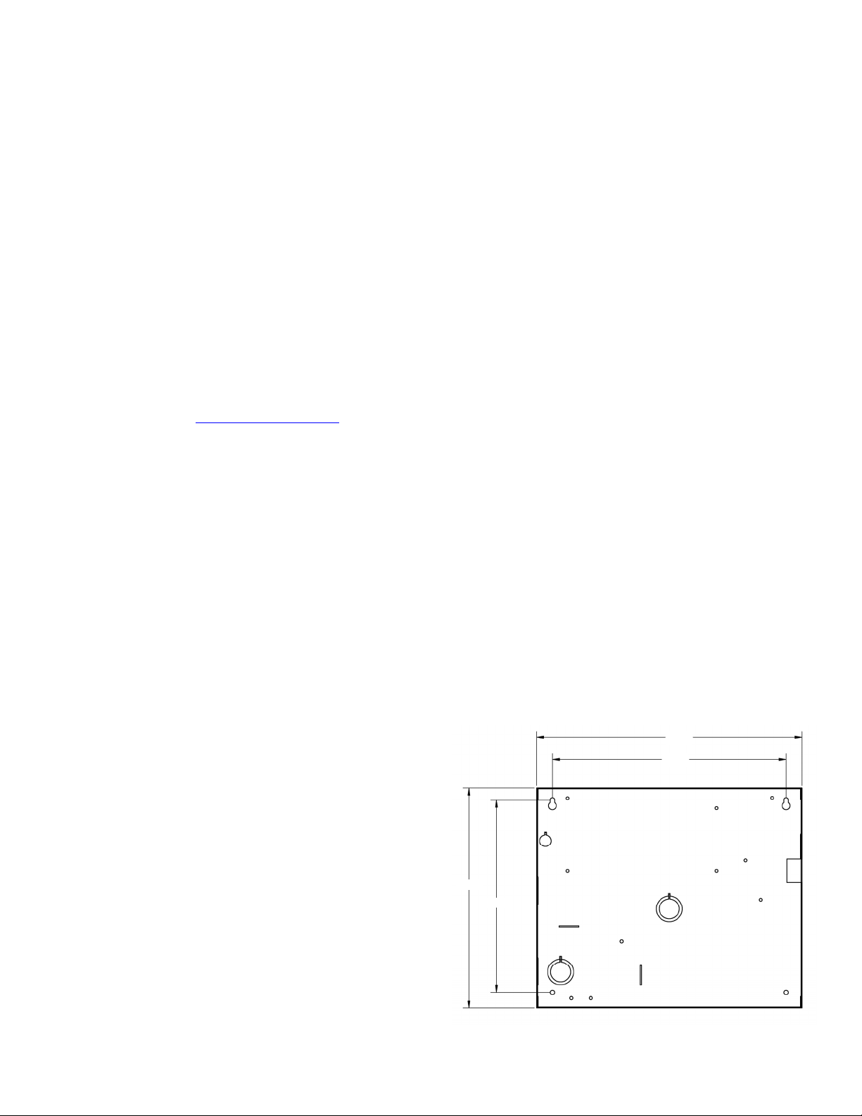
STEP 2: SELECT A MOUNTING LOCATION
The mounting location should be indoors within the protect-
ed area and selected based on RF performance. It is
HIGHLY recommended that the installer carefully adhere to
the following recommendations BEFORE any wires are
installed.
Generally, high locations are best. DO NOT mount ra-
dio in basements or below grade as unpredictable per-
formance may result.
DO NOT mount the radio in non-climate controlled envi-
ronments (i.e. attics may become extremely hot in sum-
mer, garages may become extremely cold in winter).
Avoid mounting locations within 3 feet of AC power
lines, fluorescent light fixtures, or large metal objects (air
conditioners, metal garage doors, etc.) as these loca-
tions have been shown to have a detrimental effect on
signal strength.
A fair amount of care may be required to mount the
StarLink radio so as to achieve an optimal RF path. The
installer should spend as much time as needed to obtain
the highest signal level possible.
a. Before applying power, be sure to connect the
antenna. Temporarily connect power to the
StarLink radio from a fully charged 12V (4AH mini-
mum) battery. DO NOT mount the radio at this
time. Press Tamper switch to send a signal.
b. Position the unit in the desired mounting location,
with antenna oriented vertically. The signal strength
is displayed by the Green "Signal Strength LED"
labeled "D3" (located at the lower right corner of the
PC board). The radio tower signal strength may
fluctuate from day to day, therefore it is best to try to
find a mounting location where the LED provides a
minimum of 2 blinks.
c. Once a location has been selected based on signal
coverage, permanently secure the unit using #8
screws (not supplied) in the two mounting holes.
WARNING: To ensure user safety and to satisfy FCC
RF exposure requirements, this unit must be installed so
that a minimum separation distance of 60cm (24") is al-
ways maintained between the antenna of the transmitting
device and nearby persons.
STEP 3: WIRING (PRIMARY MODE)
22-gauge wire may be used if mounted up to 50 feet from
the control panel, and 18-gauge wire should be used for up
to 100 feet. Reference the wiring diagrams further in this
manual. See the section CONTROL PANEL PROGRAM-
MING further in this manual.
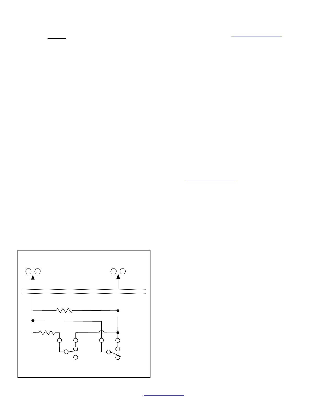
For Primary Mode:
The wiring between the control panel and the StarLink ra-
dio is over several wires, as follows:
TB1: PWR (+12V): Rated 12/24VDC input.
TB2: PWR GND (–)
TB21: N/C OUT1: Wired to the (+) of a zone dedi-
cated to monitoring the radio status. Should be pro-
grammed on Napco GEMC control panels as Monitor
or Supervisory Zone.
TELCO PRIMARY to FACP Telco 1 RJ-45 socket.
TELCO SECONDARY to FACP Telco 2 RJ-45 socket.

6 StarLink™SLE Commercial LTEVI & LTEAI Series Dual-Path Alarm Communicators -- Installation Instructions
tion in response to a triggered input event, see the table on
the previous page.
Note: These event codes and zone numbers can be
changed from the Management Center screen (located at
www.NapcoNOC.com).
Upon alarm, the NOC can optionally send an SMS mes-
sage to a third party that includes the appropriate Contact
ID alarm code, including the zone or user number, if appli-
cable. The "STARLINK RADIO RELATED EVENT RE-
PORT CODES" table also includes the most common Con-
tact ID alarm codes.
Programming StarLink Radio Troubles
It is required that if a StarLink radio or control panel trou-
ble is detected, that it is reported to the central station.
When the StarLink radio detects and sends a trouble to
the control panel, the control panel must be programmed
to annunciate this trouble. The radio can detect multiple
troubles as indicated by the "Red Trouble LED" ("D5").
For these troubles to be annunciated at the panel, there
are several methods, some of them are configurable at
the Management Center screen (www.NapcoNOC.com):
Wire the radio OUT1 relay to a dedicated control panel
zone (input) to annunciate the trouble (activate a trouble
sounder) when an open is detected. Two wiring options
are available:
Activate the trouble with an open by wiring the
EOLR in series with the Common and N/C of
the OUT1 relay;
Activate the trouble with a short by wiring the
EOLR in parallel with the Common and N/O of
the OUT1 relay
The radio must also report this trouble to the central sta-
tion. With Napco GEMC control panels, wire the zone as
indicated in the wiring diagrams further in this manual.
For models with the SLE-ULPS-R Power Supply, wire
this Power Supply trouble output relay to the two terminals
of the control panel zone dedicated to the trouble. With
the GEMC Commercial Fire control panels, use the dry
contacts of the Power Supply relay by removing the jump-
er and using the contacts of the Power Supply relay
(Common and N/O) in series with a 2.2k EOLR.
For radio models without the SLE-ULPS-R Power Supply
(powered by the control panel Aux Power terminals), wire
SIGNALS ORIGINATED AT THE NOC
NOC Originated
Alarms
Contact ID
Event Data
Sent
Initiated By Comments
Supervisory Fail E356 A00 Zn000
Automatically by NOC if fail to receive any signal
from StarLink radio within Supervisory Timeout
duration.
For Auto Enroll, uses captured telephone number,
Sub ID and format. For Dealer Programmed, uses
entered telephone number, Sub ID and format.
Press to Send
Test Signal E601 A00 Zn000
Manually by dealer from the Management Center
Signal Log screen (located at
www.NapcoNOC.com). Sends test into CS re-
ceiver.
Same comment as above.
Press to Send
Radio Test
Not Applicable
Nothing sent to
CS receiver
Manually by dealer from the Management Center
Checkins screen (located at
www.NapcoNOC.com). Sends a command to
the StarLink radio to force a check-in to the NOC.
----
STARLINK RADIO RELATED EVENT
REPORT CODES (Contact ID by default)
EVENT AREA CONTACT ID PULSE
4/2**
CODE ZONE #
IN 1 Fire 0 E110 990 1A
IN 2 Trouble 0 E373 992 F2
IN 3 Fire 0 E110 993 1A
IN 4 Supervisory 0 E200 994 00
IN 5 Water Flow 0 E113 995 13
Low Battery/Voltage 0 E302 994 F4
Tamper Trouble 0 E341 995 F5
Reboot 0 E625 997 F7
IN 1 CO (Carbon Monoxide) 0 E162 998 18
Medical Alarm* E100
24 hour Aux. Alarm* E150
24 hour Aux. Restore* R150
Keypad Emergency Alarm* E140
A.C. Trouble* E301
Tel 1 Fail* E351
Fire Polling Report E780 999 F9
Supv Failure Report E788 000 D1 or D2
Tip/Ring Wiring Fault Report E789 000 F2
Path Test Report E602 890 77
*Not generated by the StarLink radio.
**See table "NOTICE TO AUTHORITIES HAVING JURISDICTION..." on page 3.

StarLink™SLE Commercial LTEVI & LTEAI Series Dual-Path Alarm Communicators -- Installation Instructions 7
the radio directly to the 12V of the control panel. Program
the radio to report all troubles on OUT1, Common and
N/C.
You can also wire across the dedicated zone on a GEMC-
EZM8. Thus when a radio trouble is detected, the radio
OUT1 activates the control panel zone, and the panel
generates a local annunciation.
Optionally, you may also wire the FACP Trouble Relay to
IN2; Common and N/O terminals in parallel with a 10k
EOLR. With Gemini C-Series (GEMC) control panels, we
recommend using the Fire Aux Relay. Program the Fire
Aux Relay to activate as a trouble relay. Wire this relay to
the StarLink module IN2 terminal; by wiring the EOLR in
parallel with the Common and N/O of the OUT1 relay.
Note: We recommend using the text "Radio Trouble"
as the Zone Description.
StarLink Radio Supervision
If the two Telco wires (DACT interconnect wiring to the
radio) between the StarLink radio and the control panel
are cut or otherwise disconnected, the control panel must
detect and generate a local trouble indication. Program
the control panel for telephone supervision. Program the
StarLink radio using the Management Center Advanced
Features screen (at www.NapcoNOC.com) to enable
Tip/Ring Wiring Fault Report. Refer to wiring diagram.
Supervision Time Schedule Considerations
If a status change (alarm trouble, etc.) is transmitted, the
radio supervision timer is restarted.
For example, if a status change is sent, the next regular
supervision transmission will occur at the interval deter-
mined by your rate plan.
Configuration Download / Firmware Updates
Technician on site required.
For Commercial Installations a technician is required to be
on site during any reprogramming of the radio or control
panel and must perform / re-perform acceptance testing.
To perform a download or update the radio firmware,
jumper 1 must be removed. UL requires that the jumper
be replaced after the download is complete. Failure to
replace the jumper would allow downloads to the ra-
dio without a technician on-site.
For Residential installations jumper 1 may be removed to
permit uploading and downloading without a technician on
site, however, the dealer is responsible for ensuring the
system is operating correctly after any downloads or
changes to the system.
Cover Tamper
The SLE series radios in the metal housings may option-
ally have front and rear tamper switches installed (GEM-
Tamperkit) and wired to the control panel (see page 14).
Note: The tamper switch on the radio PC board is not
used in this housing (but continues to function if pressed).
10-1/8"
11-1/2"
9-1/2"
9-21/64"
Red and White Metal Housing Dimensions (inches)

8 StarLink™SLE Commercial LTEVI & LTEAI Series Dual-Path Alarm Communicators -- Installation Instructions
This page intentionally left blank

StarLink™SLE Commercial LTEVI & LTEAI Series Dual-Path Alarm Communicators -- Installation Instructions 9
LOCAL
DOWNLOAD
TELCO
SECONDARY
TELCO
PRIMARY ETHERNET
1
(+)
2
(‒)
POWER PGM3 IN1 IN2 IN3
3
(‒)
4
(+)
5
(+)
6
(‒)
8
(‒)
7
(+)
9
(+)
10
(‒)
12
(‒)
11
(+)
13
EGND 19
N/O
21
N/C
20
C
IN4 IN5 OUT1
22
N/C
24
N/O
23
C
OUT2
(Commercial Fire) SLE-LTEVI-CFBPS & SLE-LTEAI-CFBPS
Wiring Diagram
SLE-LTEVI-CFBPS & SLE-LTEAI-CFBPS
PC Board
All connections are power limited except AC
Mains and battery terminals Power Supply
(SLE-ULPS-R)
Yellow
Trouble
LED
Green AC
ON LED
+ BAT –
RED BLK
6 72 3 4 51
8 9 10
N/C COM N/O
Black (‒)
Red (+)
Battery
.5A
Fuse
16.5VAC
Class 2
*Notes:
Connect the StarLink radio to the control panel output for Telco Trouble (this is the DACT interconnect wiring to the radio). Remember to
program the StarLink communicator module to report this IN2 Telco Trouble and for line cut (EOLR) to the central station. In addition,
always add an EOLR at the control panel Telco Trouble Output (Fire Aux Relay for the GEMC control panels).
Use EOLR value as specified by the control panel installation instructions.
IN1 not supervised. IN2, IN3, IN4 and IN5 can be supervised.
Licensed electrician required to wire the 120VAC connections to the transformer in accordance with N.E.C. and local code requirements.
Refer to section "SUPPLYING POWER".
Route 120VAC only through the transformer compartment knockouts.
Keep all non-power limited wiring separate from all power-limited wiring inside the housing by 1/4". In addition, maintain a minimum 1/4"
separation of all primary wiring in the transformer compartment from the yellow secondary wires of the transformer.
Remove shunt J2 to isolate relay OUT1 common from ground (i.e. jumper on = wet (circuit common); off = dry contact). When wet,
configuration is used; the power should be derived from the alarm control panel.
OUT1 N/C (terminal 21) of the StarLink module must be programmed for any radio trouble and wired to the FACP trouble input if
JP2 shunt is not removed and Telco 2 is not monitored.
The Power Supply Relay Trouble Output must be wired to FACP Zone input dedicated to communicator trouble, unless JP2 is removed and
Telco 2 is monitored. When JP2 is removed and Telco 2 is monitored, the power supply trouble relay should be wired to IN4 with a series
resistor to terminal 9 (remove EOLR) and IN4 programmed to report a Power Supply trouble.
IN1+ 12V –AC IN
Note: Maintain
minimum 1/4"
separation of
battery leads from
all other wiring.
EOLR*
J2
Chassis Mounted 16.5VAC / 20VA Transformer
BLK
Note: Maintain minimum 1/4" separation
of all wiring in this compartment from
the yellow wires of the transformer.
Relay con-
tacts rated
max 30VDC,
0.5A
12VDC
output is
power
limited
(Earth Ground)
Note: Connect IN2 to a
panel output used for
identifying Telco line cut (this
is the DACT interconnect
wiring to the radio).
TRF12/T123
16.5V / 20VA
Transformer
or
(To control panel*)
Remove shunt J2 to isolate relay OUT1
common from ground (i.e. jumper on =
wet (circuit common); off = dry contact).
JP1
Shunt JP1 on
bottom 2 pins
10kΩ
10kΩ
10kΩ
10kΩ
To FACP Telco
1 & 2 (or Primary
& Secondary)
JP2
Remove JP2 to
enable TELCO2
trouble on
Communicator trouble

10 StarLink™SLE Commercial LTEVI & LTEAI Series Dual-Path Alarm Communicators -- Installation Instructions
Wiring Diagram for Generic FACPs
with TELCO RJ Sockets
FACP PC BOARD
(CONTROL PANEL HOUSING)
Refer to section "SUPPLYING POWER".
TELCO RJ SOCKET (SECONDARY)
Optional: When Power Supply
SLE-ULPS-R is not used, connect
FACP Aux Power or Listed power
supply (+12V or +24V) to StarLink
terminals 1 and 2 (observing
polarity)
(+) (‒)
+12V or +24V
AUX PWR
(STARLINK RADIO HOUSING)
StarLink Radio Terminals
PC Board: All connections are power limited except AC Mains and battery terminals.
LOCAL
DOWNLOAD
TELCO
SECONDARY
TELCO
PRIMARY ETHERNET
1
(+)
2
(‒)
POWER PGM3 IN1 IN2 IN3
3
(‒)
4
(+)
5
(+)
6
(‒)
8
(‒)
7
(+)
9
(+)
10
(‒)
12
(‒)
11
(+)
13
EGND 19
N/O
21
N/C
20
C
IN4 IN5 OUT1
22
N/C
24
N/O
23
C
OUT2
Power Supply (SLE-ULPS-R)
Either the TRF12/
T123 (16.5V /
20VA) transformer
or the chassis-
mounted 16.5VAC /
20VA transformer
Optional; if not used, connect 10K
resistor between terminals 9 and
10 (IN4)
StarLink
BATTERY
(+)
RED (–)
BLACK
8 9 10
N/C COM N/O
J2
Note: Battery
leads are not
power limited
10kΩ
10kΩ
10kΩ
TELCO RJ SOCKET (PRIMARY)
EOLR
(J2 jumper off)
(This connection only used with
Power Supply SLE-ULPS-R)
The feature "Tip/Ring
Wiring Fault Report" is
required for supervision.
Requires all 8 wires in
the RJ-45 cable
JP1
Shunt JP1 on
bottom 2 pins
when using the
SLE-ULPS-R
Shunt on top 2
pins when NOT
using the SLE-
ULPS-R
(These connections
only used without
Power Supply)
EOLR
JP2
Remove shunt
on JP2 to enable
TELCO 2 trouble
*Not required if JP2 shunt is removed and FACP monitors TELCO 2.
To FACP Zone
Dedicated to Radio
Trouble*
When using JP2 option (monitoring Telco 2) with power supply wire:
1. Move Power Supply IN1 from Radio OUT1 terminal 21 to power
supply terminal 4 (-).
2. Do not wire power supply trouble relay to FACP zone.
3. Wire power supply terminal in series with 10K EOLR to Radio
IN4 (+).
4. Program IN4 to report power supply trouble.

StarLink™SLE Commercial LTEVI & LTEAI Series Dual-Path Alarm Communicators -- Installation Instructions 11
(STARLINK RADIO HOUSING)
StarLink Radio Terminals
PC Board: All connections are power limited except AC Mains and battery terminals.
LOCAL
DOWNLOAD
TELCO
SECONDARY
TELCO
PRIMARY ETHERNET
1
(+)
2
(‒)
POWER PGM3 IN1 IN2 IN3
3
(‒)
4
(+)
5
(+)
6
(‒)
8
(‒)
7
(+)
9
(+)
10
(‒)
12
(‒)
11
(+)
13
EGND 19
N/O
21
N/C
20
C
IN4 IN5 OUT1
22
N/C
24
N/O
23
C
OUT2
Wiring Diagram for Generic FACPs
without TELCO RJ Sockets
FACP PC BOARD
(CONTROL PANEL HOUSING)
SECONDARY TELCO PRIMARY TELCO
IN PHONES IN PHONES
10kΩ
Power Supply (SLE-ULPS-R)
Either the TRF12/
T123 (16.5V /
20VA) transformer
or the chassis-
mounted 16.5VAC /
20VA transformer
Optional; if not used, connect 10K
resistor between terminals 9 and
10 (IN4)
StarLink
BATTERY
(+)
RED (–)
BLACK
8 9 10
N/C COM N/O
J2
Note: Battery
leads are not
power limited
Optional: When Power Supply
SLE-ULPS-R is not used, connect
FACP Aux Power or Listed power
supply (+12V or +24V) to StarLink
terminals 1 and 2 (observing
polarity)
10kΩ
(+) (‒)
+12V or +24V
AUX PWR
10kΩ
10kΩ
Refer to section "SUPPLYING POWER".
DO NOT
USE EOLR
EOLR
(J2 jumper off)
(This connection only used with
Power Supply SLE-ULPS-R)
(These connections only
used without Power Supply) To FACP Zone
Dedicated to Radio
Trouble*
EOLR
JP1
--Shunt JP1 on
bottom 2 pins
when using the
SLE-ULPS-R
--Shunt on top 2
pins when not
using the SLE-
ULPS-R
RJ31X
RING TIP
GREEN
RED
GREEN
RED
WIRE DIRECTLY TO CONTROL
PANEL (USE FOR SHORTER DISTANCES)
OPTIONAL: WIRE TO RJ31X
(USE FOR LONGER DISTANCES)
RJ31X
RING TIP
GREEN
RED
WIRE DIRECTLY TO CONTROL
PANEL (USE FOR SHORTER DISTANCES)
OPTIONAL: WIRE TO RJ31X
(USE FOR LONGER DISTANCES)
GREEN
The feature "Tip/Ring Wiring Fault
Report" is required for supervision.
RED
JP2
Remove shunt
on JP2 to enable
TELCO 2 trouble
*Not required if JP2 shunt is removed and FACP monitors TELCO 2.
When using JP2 option (monitoring Telco 2) with power supply wire:
1. Move Power Supply IN1 from Radio OUT1 terminal 21 to power
supply terminal 4 (-).
2. Do not wire power supply trouble relay to FACP zone.
3. Wire power supply terminal in series with 10K EOLR to Radio
IN4 (+).
4. Program IN4 to report power supply trouble.

12 StarLink™SLE Commercial LTEVI & LTEAI Series Dual-Path Alarm Communicators -- Installation Instructions
(STARLINK RADIO HOUSING)
StarLink Radio Terminals
LOCAL
DOWNLOAD
TELCO
SECONDARY
TELCO
PRIMARY ETHERNET
1
(+)
2
(‒)
POWER PGM3 IN1 IN2 IN3
3
(‒)
4
(+)
5
(+)
6
(‒)
8
(‒)
7
(+)
9
(+)
10
(‒)
12
(‒)
11
(+)
13
EGND 19
N/O
21
N/C
20
C
IN4 IN5 OUT1
22
N/C
24
N/O
23
C
OUT2
Wiring Diagram for GEMC-32, GEMC-96,
GEMC-128 and GEMC-255 Control Panels
(CONTROL PANEL HOUSING)
**
GEMC Control Panel
PC Board
Refer to section "SUPPLYING POWER".
*Not required if JP2 shunt is removed and FACP
monitors TELCO 2.
**Program only TELCO 1 supervision.
Note: Connect IN2 to a panel output
used for identifying Telco line cut (this is
the DACT interconnect wiring to the radio).
PC Board: All connections are power limited except AC Mains and battery terminals.
Or use a
12V/24V UL
Listed
monitored
power supply
10kΩ
10kΩ
10kΩ
EOLR
Requires all 8 wires in
the RJ-45 cable
JP1
Shunt JP1
on top 2 pins
(Optional, for remote
communication)
JP2
Remove JP2 to
enable TELCO2
trouble on
Communicator trouble
To Panel Zone
Dedicated to Radio
Trouble*

StarLink™SLE Commercial LTEVI & LTEAI Series Dual-Path Alarm Communicators -- Installation Instructions 13
Alternate Telco Line to Alarm Panel Supervision
The following wiring and programming method allows an existing FACP to use its two telephone connections
(primary and secondary) for supervision and central station reporting through the StarLink SLE-LTEVI-FIRE radio.
By removing the JP2 shunt and enabling the feature "Tip/Ring Wiring Fault Report", when any radio trouble is
detected, the StarLink radio will remove voltage from the secondary telephone output, triggering the FACP to
locally annunciate the Telco trouble and report the trouble to the central station.
NOTES

14 StarLink™SLE Commercial LTEVI & LTEAI Series Dual-Path Alarm Communicators -- Installation Instructions
WIRING THE TAMPER SWITCHES
Before installation and wiring, the tamper switches (part GEM-
Tamperkit) are normally open devices; when placed into
the circuit and into operation, they are normally closed devic-
es.
Tamper switches protect against the opening of the radio cabi-
net door or the removal of the radio enclosure from the wall or
other mounting surface.
There are two places in the cabinet to mount tamper switches:
(1) To prevent cabinet removal from the wall, located on the
left side of the cabinet there is one knockout for the switch
plunger and three mounting holes (in the enclosure sheet met-
al). (2) To protect the cabinet door, mount a tamper switch in
the three mounting holes (in the enclosure sheet metal).
When mounted, the switch button contacts the inside surface
of the door. Note: Be sure to alert the user that opening the
enclosure door will cause a tamper alarm.
Wiring a normally closed sensor loop for tamper supervision,
wire to a zone on the control panel.
GEM-Tamperkit
consists of Description QTY
SC206LF Slotted Pan Head 6-32 x 3/4
Machine Screw 6
SW105 Tamper Switch 2
Tamper Switch Mounting Instructions
Back Tamper
Door Tamper
VIEW OF TAMPER SWITCHES:
(1) = ENCLOSURE BASE;
(2-BACK) = TAMPER SWITCH TO PREVENT REMOVAL FROM WALL;
(3-DOOR) = TAMPER SWITCH TO PROTECT THE ENCLOSURE
DOOR
1
3
2
Name Format Type Handshake Frequency Speed
Ademco Slow 4/2 1400 Hz or 2300Hz 10pps
Ademco Slow 4/2 checksum 1400 Hz or 2300Hz 10pps
Radionics Slow 4/2 2300Hz 10pps
Radionics Slow 4/2 checksum 2300Hz 10pps
Silent Knight Fast 4/2 1400 Hz or 2300Hz 20pps
Silent Knight Fast 4/2 checksum 1400 Hz or 2300Hz 20pps
Radionics Fast 4/2 2300Hz 40pps
Radionics Fast 4/2 checksum 2300Hz 40pps
Universal High Speed 4/2 1400 Hz or 2300Hz 40pps
Universal High Speed 4/2 checksum 1400 Hz or 2300Hz 40pps
4/2 Pulse Dialing
Format
Compatibility
Note: The SLE Dual-Path Series Radios
are compatible with any Listed 4/2
Receiver such as the Ademco 685.

StarLink™SLE Commercial LTEVI & LTEAI Series Dual-Path Alarm Communicators -- Installation Instructions 15
8 IN.
8 IN.
FRONT VIEW
4 to 6 IN.
SIDE VIEW
EXAMPLE OF CONDUIT LOCATION
COVER
UL LISTED ELECTRICAL PULL BOX WITH LISTED OUTLET BOX AND NON-SWITCHED RECEPTACLE
ON DEDICATED FIRE ALARM SYSTEM BRANCH CIRCUIT
CONDUIT TRANSFORMER OUTPUT WIRING
UL LISTED PULL BOX
UL LISTED NAPCO TRF12/T123 TRANSFORMER FOR
CONNECTION TO SLE CHARGER BOARD
UL LISTED SURFACE OR FLUSH MOUNT OUTLET BOX
AND NON-SWITCHED RECEPTACLE
WALL
TRANSFORMER SECONDARY WIRING CONDUIT LIMITED TO 20 FEET MAXIMUM LENGTH
Maintain a minimum of 1/4 inch separation of
circuits (transformer secondary wiring from
120V branch circuit).
EXAMPLE
OF
CONDUIT
LOCATION
Optional Alternate Methods for Commercial Fire
Branch Circuit Power Connections to the SLE Charger Board
Minimum Pull
Box
Dimensions
Min. 4 inch with flush
mount receptacle
and min. 6 inch with
surface mount
receptacle
CONDUIT
120V

16 StarLink™SLE Commercial LTEVI & LTEAI Series Dual-Path Alarm Communicators -- Installation Instructions
NAPCO SECURITY TECHNOLOGIES, INC. (NAPCO) warrants its
products to be free from manufacturing defects in materials and
workmanship for 36 months following the date of manufacture. NAPCO
will, within said period, at its option, repair or replace any product failing to
operate correctly without charge to the original purchaser or user.
This warranty shall not apply to any equipment, or any part thereof, which
has been repaired by others, improperly installed, improperly used,
abused, altered, damaged, subjected to acts of God, or on which any
serial numbers have been altered, defaced or removed. Seller will not be
responsible for any dismantling or reinstallation charges.
THERE ARE NO WARRANTIES, EXPRESS OR IMPLIED, WHICH
EXTEND BEYOND THE DESCRIPTION ON THE FACE HEREOF.
THERE IS NO EXPRESS OR IMPLIED WARRANTY OF
MERCHANTABILITY OR A WARRANTY OF FITNESS FOR A
PARTICULAR PURPOSE. ADDITIONALLY, THIS WARRANTY IS IN
LIEU OF ALL OTHER OBLIGATIONS OR LIABILITIES ON THE PART
OF NAPCO.
Any action for breach of warranty, including but not limited to any implied
warranty of merchantability, must be brought within the six months
following the end of the warranty period. IN NO CASE SHALL NAPCO BE
LIABLE TO ANYONE FOR ANY CONSEQUENTIAL OR INCIDENTAL
DAMAGES FOR BREACH OF THIS OR ANY OTHER WARRANTY,
EXPRESS OR IMPLIED, EVEN IF THE LOSS OR DAMAGE IS CAUSED
BY THE SELLER'S OWN NEGLIGENCE OR FAULT.
In case of defect, contact the security professional who installed and
maintains your security system. In order to exercise the warranty, the
product must be returned by the security professional, shipping costs
prepaid and insured to NAPCO. After repair or replacement, NAPCO
assumes the cost of returning products under warranty. NAPCO shall
have no obligation under this warranty, or otherwise, if the product has
been repaired by others, improperly installed, improperly used, abused,
altered, damaged, subjected to accident, nuisance, flood, fire or acts of
God, or on which any serial numbers have been altered, defaced or
removed. NAPCO will not be responsible for any dismantling, reassembly
or reinstallation charges.
This warranty contains the entire warranty. It is the sole warranty and any
prior agreements or representations, whether oral or written, are either
merged herein or are expressly cancelled. NAPCO neither assumes, nor
authorizes any other person purporting to act on its behalf to modify, to
change, or to assume for it, any other warranty or liability concerning its
products.
In no event shall NAPCO be liable for an amount in excess of NAPCO's
original selling price of the product, for any loss or damage, whether
direct, indirect, incidental, consequential, or otherwise arising out of any
failure of the product. Seller's warranty, as hereinabove set forth, shall not
be enlarged, diminished or affected by and no obligation or liability shall
arise or grow out of Seller's rendering of technical advice or service in
connection with Buyer's order of the goods furnished hereunder.
NAPCO RECOMMENDS THAT THE ENTIRE SYSTEM BE
COMPLETELY TESTED WEEKLY.
Warning: Despite frequent testing, and due to, but not limited to, any or
all of the following; criminal tampering, electrical or communications
disruption, it is possible for the system to fail to perform as expected.
NAPCO does not represent that the product/system may not be
compromised or circumvented; or that the product or system will prevent
any personal injury or property loss by burglary, robbery, fire or otherwise;
nor that the product or system will in all cases provide adequate warning
or protection. A properly installed and maintained alarm may only reduce
risk of burglary, robbery, fire or otherwise but it is not insurance or a
guarantee that these events will not occur. CONSEQUENTLY, SELLER
SHALL HAVE NO LIABILITY FOR ANY PERSONAL INJURY,
PROPERTY DAMAGE, OR OTHER LOSS BASED ON A CLAIM THE
PRODUCT FAILED TO GIVE WARNING. Therefore, the installer should
in turn advise the consumer to take any and all precautions for his or her
safety including, but not limited to, fleeing the premises and calling police
or fire department, in order to mitigate the possibilities of harm and/or
damage.
NAPCO is not an insurer of either the property or safety of the user's
family or employees, and limits its liability for any loss or damage
including incidental or consequential damages to NAPCO's original
selling price of the product regardless of the cause of such loss or
damage.
Some states do not allow limitations on how long an implied warranty
lasts or do not allow the exclusion or limitation of incidental or
consequential damages, or differentiate in their treatment of limitations of
liability for ordinary or gross negligence, so the above limitations or
exclusions may not apply to you. This Warranty gives you specific legal
rights and you may also have other rights which vary from state to state.
NAPCO LIMITED WARRANTY
To terminate more than two conductors or
conductors of different wire sizes to a terminal,
use the "pigtail" type wiring method as shown at
right. Use insulated wire for the pigtail, and firmly
secure the conductors to the pigtail using an ap-
propriate wire nut or crimp connector for the num-
ber and gauge of conductors used.
IMPORTANT WIRING METHODS
Incorrect
Correct -- Use pigtail and wire nut / crimp connector
PIGTAIL
WIRE NUT OR
CRIMP
CONNECTOR
PIGTAIL
For single-conductor terminal
blocks (like the type shown at
left), to terminate more than one
conductor to a terminal, use the
wiring methods shown at right:
WIRE NUT OR
CRIMP
CONNECTOR
PIGTAIL
Correct -- Single incoming and/or pigtail with wire nut / crimp connectors
In
For "barrier" type terminal
blocks (like the type shown at
left), to terminate two conductors
to a terminal, use the wiring meth-
ods shown at right: Correct -- Separate incoming and outgoing conductors
In Out
Incorrect
Incorrect
In Out
NOTE: This equipment has been tested and found to comply with the limits for a Class B Unintentional Radiator, pursuant to
Part 15 of the FCC Rules. These limits are designed to provide reasonable protection against harmful interference in a residential
installation. This equipment generates, uses, and can radiate radio frequency energy and, if not installed and used in accordance with the
Instruction Manual, may cause harmful interference to radio communications. However, there is no guarantee that interference will not
occur in a particular installation. If this equipment does cause harmful interference to radio or television reception, which can be
determined by turning the equipment off and on, the user is encouraged to try to correct the interference by one of more of the following
measures: 1. Reorient or relocate the receiving antenna; 2. Increase the separation between the equipment and receiver; 3. Connect the
equipment into an outlet on a circuit different from that to which the receiver is connected; 4. Consult the dealer or an experienced radio/
TV technician for help.
This manual suits for next models
5
Table of contents
Other NAPCO Cell Phone manuals

NAPCO
NAPCO StarLink SLE User manual

NAPCO
NAPCO StarLink SLE-LTEVI-FIRE User manual

NAPCO
NAPCO Gemini GEM-P816 User manual

NAPCO
NAPCO StarLink SLE-LTEVI-FIRE User manual

NAPCO
NAPCO StarLink Connect Series User manual

NAPCO
NAPCO StarLink Full Data SL-1FD-T User manual

NAPCO
NAPCO StarLink SLE Series User manual

NAPCO
NAPCO Gemini GEM-P1632 Installation manual

NAPCO
NAPCO StarLink SLE Series User manual

NAPCO
NAPCO StarLink SLE-LTEV-SS User manual