NAPCO Gemini GEM-P1632 Installation manual

HARDWIRE WIRELESS
GEM-P1632
CONTROL PANEL/COMMUNICATOR
Programming the GEM-P1632 Control Panel with the
"Classic" GEM-RP2ASe2, GEM-RP3DGTL, and GEM-RP4RFC/GEM-RP4C Keypads and
the "K Series" GEM-K2AS, GEM-K3DGTL, and GEM-K4/GEM-K4RF Keypads
WI1148B 10/06
© NAPCO 2006
Quick Start (for GEM-K2AS):
1. Refer to the wiring diagram, connect Siren, Aux. Power,
PGM Output, Remote Bus, Earth Ground, Zone and Tele-
phone Wiring. NOTE: See Installation Instructions (WI808).
2. Connect AC power first and then the battery.
3. Configure the keypad (see page 55).
4. Access the Easy Menu Driven (Dealer Program) Mode:
Press
456789 R
Press NO until “TURNON PROG Y/N” appears on the keypad display.
Press NEXT/YES to enter Dealer Program Mode. See page 5.
Dealer Code
Quick Start (for GEM-K3DGTL):
1. Refer to the wiring diagram, connect Siren, Aux. Power,
PGM Output, Remote Bus, Earth Ground, Zone and Tele-
phone Wiring. NOTE: See Installation Instructions (WI808).
2. Connect AC power first and then the battery.
3. Configure the keypad (see page 55).
4. Access the Easy Menu Driven (Dealer Program) Mode:
Press
456789 R
Press NO until “17” appears on the keypad display.
Press NEXT/YES to enter Dealer Program Mode. See page 5.
Dealer Code
PROGRAMMING
INSTRUCTIONS
R
"K Series" GEM-K2AS
R
COMPUTERIZED SECURITY SYSTEM
ARMED
STATUS
SYSTEM ARMED
01/01/97 12:00AM
12
4
3
56
7890
A
B
C
D
E
F
G
NEXT/YES
PRIOR/NO
AREA
GEMINI
READY
AC ON
READY
AC ON
R
R
COMPUTERIZED SECURITY SYSTEM
ARMED
STATUS
SYSTEM ARMED
01/01/97 12:00AM
12
4
3
56
7890
A
B
C
D
E
F
G
NEXT/YES
PRIOR/NO
AREA
GEMINI
ENT A1
32
INT ER IOR BYPASS FIRE/TBL SYS T BL CHIME
"K Series" GEM-K3DGTL
R
"K Series" GEM-K4/GEM-K4RF
Publicly traded on NASDAQ Symbol: NSSC

THIS MANUAL INCLUDES FEATURES WHICH ARE ONLY AVAILABLE IN
CONTROL PANEL FIRMWARE VERSION 30B OR LATER.
NAPCO Security Systems, Inc.
333 Bayview Avenue, Amityville, New York 11701
For Sales and Repairs, call toll free: (800) 645-9445
For direct line to Technical Service, call toll free: (800) 645-9440
Internet: http://www.napcosecurity.com
IMPORTANT NOTE
This manual supports the keypad programming of the GEM-P1632 control panel with the NAPCO "classic" GEM-
RP2ASe2, GEM-RP3DGTL and GEM-RP4RFC series keypads as well as the GEM-K2AS, GEM-K3DGTL and GEM-
K4RF "K Series" keypads. The new "K Series" models offer the new STAY and AWAY buttons with simplified function-
ality, along with the new MENU and ENTER buttons. While the instructions in this manual are depicted using the "K Se-
ries" keypads, the manual applies to both the "classic" and the "K Series" keypads.
Program Mode is the same for both keypads--only the button names have changed, as follows:
•The Abutton and the Rbutton operate identically (in Program Mode) for both keypads.
•The Dbutton and the Ubutton operate identically (in Program Mode) for both keypads.
•The button and the button operate identically (in Program Mode) for both keypads. The words
"NEXT/YES button" are used in this manual.
•The button and the button operate identically (in Program Mode) for both keypads. The words
"PRIOR/NO button" are used in this manual.
For consistency, it is recommended that all keypads either be all "classic" or all "K Series"--both keypad
types should not be used in one alarm system.
CHANGES FROM PREVIOUS EDITION
The following changes have been made to this manual (WI1148B) since the previous edition (WI1148A):
•Added new feature to address 2054 bit 2 (option 3) "TCP/IP Panel/Site Initiated Functions" on page 29.
•Added new feature to addresses 0461, 0483 and 0505 bit 6 (option 7) "Enable TCP/IP AES RPT" on page 30.

LNAPCO Security Systems XGEM-P1632 Programming Instructions
Page 3
WI1148B 10/06
TABLE OF CONTENTS
Refer to accompanying GEM-P1632 Installation Instructions (WI808) for installation information.
NOTE: THESE PROGRAMMING INSTRUCTIONS ARE INTENDED AND WRITTEN FOR THE PROFESSIONAL INSTALLER HAVING SUITABLE
EXPERIENCE AND INSTALLATION EQUIPMENT. THE UNIT IS DESIGNED TO BE PROGRAMMED USING AN IBM-COMPATIBLE
COMPUTER WITH NAPCO PCD-WINDOWS SOFTWARE. AFTER PROGRAMMING, BE SURE TO RUN THE PCD-WINDOWS ERROR-CHECK
UTILITY TO GUARD AGAINST PROGRAMMING CONFLICTS FOR THE TYPE OF SERVICE SELECTED FOR THE INSTALLATION.
SYSTEM PROGRAMMING OPTIONS ..................................... 4
Introduction ......................................................................... 4
Downloading From a Computer........................................... 4
EASY MENU DRIVEN PROGRAM MODE............................... 5
Dealer Program - Preliminary Information ........................... 5
Accessing Dealer Program Mode........................................ 5
Customizing a Default Program........................................... 5
Easy Program Menu:
GEM-RP2ASe2/GEM-K2AS KEYPAD........................ 6
GEM-RP3DGTL/GEM-K3DGTL and
GEM-RP4RFC/GEM-K4RF KEYPAD ................... 13
DIRECT ADDRESS PROGRAM MODE................................... 20
Keypad Programming Overview.......................................... 20
Accessing Direct Address Program Mode ........................... 20
Keypad Address Program Mode Display............................. 21
Direct Address Program Mode Keypad Commands ............ 21
Direct Address Programming Example................................ 22
Conventions Used in this Manual........................................ 23
SYSTEM DELAYS & TIMEOUTS........................................ 24
SYSTEM OUTPUT TIMEOUTS .......................................... 25
DOWNLOAD/CALLBACK OPTIONS .................................. 25
PAGER FORMAT OPTIONS............................................... 25
SYSTEM OPTIONS ........................................................... 26
GLOBAL AMBUSH CODE .................................................. 26
SYSTEM OPTIONS ............................................................ 27
CS RECEIVER OPTIONS................................................... 30
CS SUBSCRIBER ID OPTIONS ........................................ 31
CS SYSTEM REPORTING OPTIONS ................................ 32
CS AREA & SYSTEM REPORTING OPTIONS................... 32
CS ZONE REPORTING OPTIONS .................................... 33
CS USER REPORTING OPTIONS .................................... 34
CS USER REPORTING OPTIONS .....................................35
EZM GROUP OPTIONS .....................................................36
AREA ARMING OPTIONS ..................................................36
AREA BELL CONTROL OPTIONS .....................................37
KEYPAD OPTIONS ............................................................41
TEMPERATURE DISPLAY AT KEYPAD ............................42
ZONE OPTIONS - ZONES 1 TO 16 ....................................43
ZONE OPTIONS - ZONES 17 TO 32 ..................................44
EXTERNAL RELAY CONTROL ..........................................47
RF RECEIVER & SUPERVISORY TIMER OPTIONS .........50
CLEAR PROGRAM OPTIONS ...........................................51
USER PROGRAM MODE .........................................................51
Preliminary Information ........................................................51
Accessing User Program Mode............................................51
User Codes..........................................................................52
KEYPAD CONFIGURATION MODE .........................................53
Keypad Installation...............................................................53
Configuring the Keypads......................................................53
ALPHABETICAL INDEX............................................................54
ADDRESS NUMBER LOCATION INDEX..................................59
GEM-P1632 WIRING DIAGRAM...............................................64

XGEM-P1632 Programming Instructions LNAPCO Security Systems
Page 4 WI1148B 10/06
SYSTEM PROGRAMMING OPTIONS
INTRODUCTION
The GEM-P1632 control panel may be programmed by various means, each of which will be covered in detail in the
sections that follow. Keypad displays shown are for a GEM-K2AS, GEM-K3DGTL and GEM-K4RF series keypads.
With the GEM-RP2ASe2 and GEM-K2AS keypads, because of their reduced display capabilities, messages are
abbreviated and will scroll through two or more screens. Zone descriptions cannot be programmed using GEM-K2AS
or GEM-RP2ASe2 keypad, therefore a GEM-RP1CAe2/GEM-K1CA must be used (see WI897).
Downloading From a Computer. This is the preferred method of programming. The panel may be
downloaded from (or uploaded to) an IBM PC-compatible computer, either locally or remotely. Napco's PCD-
Windows Quickloader software features context-sensitive help screens as well as an error-checking utility that
prevents programming of incompatible or conflicting data to ensure proper panel operation. Note: Unattended
downloading from a computer is not allowed for Fire Alarm or UL installations.
Easy Menu-Driven Program (Dealer Program) Mode - Keypad Programming. The Easy Menu-Driven
Program Mode allows keypad programming of number of zones in area 1, panel zone doubling, number of fire
zones (both 4-wire and 2-wire), local or Central Station reporting, number of exit/entry zones, number of interior
zones, number of 24 hour zones, number of chime zones, Chime 2 zones, Exit/Entry2 zones, 50ms loop re-
sponse zones (Note: 750mS is required for Loop Response time in UL installations), aux output activated on alarm
zones, sensor watch zones, keypad sounder on alarm zones, auto bypass re-entry zones, EOLR zones, number
of keypads in area 1, Central Station telephone number, Central Station account number, Central Station re-
ceiver format, User Codes, RF transmitter points, RF keyfob transmitters, zone descriptions, dealer code, Telco
line fault test, Burg output chirp on keyfob, enable CP-01, and clear dealer program/cold start. For new panels, a
custom default program may be created at the keypad. A menu-driven utility prompts the installer to configure
the system. Further detailed customization is accomplished in the Direct Address Program Mode.
Direct Address (Dealer Program) Program Mode - Keypad Programming. The Direct Address Program
Mode is an extension of the Dealer Program Mode wherein data is entered at the keypad by specific location.
This mode is accessed from the Easy Menu Driven Program Mode by pressing the Cbutton at any time.
User Program Mode - Keypad programming. The User Program Mode is intended for authorized users and is
limited to keypad programming of User Codes.
DOWNLOADING FROM A COMPUTER
The control-panel program may be downloaded from the computer by any of the following methods.
Local Downloading
(Note: This procedure should be used after installation, after peripheral devices are connected).
For direct high-speed data transfer to the control panel from a desktop computer, connect the download jack
(JP2) on the panel to the LOCAL jack (J3) on the Napco PCI2000/3000 computer interface using the supplied 6-
conductor cable. (Refer to PCI2000/3000 Installation Instructions WI443 for wiring diagram and procedures).
Similarly, a high-speed local download may be made in the field using a notebook or laptop computer. Connect
JP2 on the control panel to a Napco PCI-MINI computer interface using the 6-conductor cable supplied. (Refer
to PCI-MINI Installation Instructions WI767).
Remote Downloading
(Also see PCI2000/3000 Installation Instructions WI443). Note: Unattended downloading from a computer is not
allowed for Fire Alarm or UL installations.
Function Mode.
Start by establishing a Telco connection between the computer operator and the installer. During this procedure,
voice contact will be lost, therefore both the installer and the computer operator should be familiar with the
operation. When a steady high-pitched tone is heard at the site phone, access the “ACTIVATE DOWNLOAD” Function
(see Keypad Programming Modes), then press the Ubutton or the YES button; the site phone will go dead.
Hang up the phone and wait for a call from the central station confirming a successful download.
Callback Method.
An installed, unattended panel may be programmed or reprogrammed remotely using the Callback-Method
Download feature of the PCD Windows software. Remote downloading requires a modem compatible with the
PCI2000/3000. Upon answering the call from the computer, the panel will verify the Download Security Code
and, if confirmed, will establish a connection. If a Callback Number is programmed into the panel, the panel will
automatically disconnect and call the computer at this number before establishing a connection.
System Programming Options

LNAPCO Security Systems XGEM-P1632 Programming Instructions
Page 5
WI1148B 10/06
EASY MENU DRIVEN PROGRAM MODE
DEALER PROGRAM - PRELIMINARY INFORMATION
The Default Dealer Code is 456789. Use this code to enter the Dealer Program Mode
to program a custom Dealer Code, which replaces the Default Dealer Code. If you clear your Dealer Code, use the Default
Dealer Code once again to enter programming.
After entering codes or data, press the save Ubutton. Data will not be stored into memory unless Uis pressed.
If the keypad is in the Program Mode and no activity is detected for longer than 4 minutes, a steady tone will sound.
Silence the sounder by the Gbutton to continue, or by pressing the Cbutton to exit.
When programming a Multiple Area System, Direct Address Programming Mode must be used to complete the program.
1. Press 456789 R
2. Press "PRIOR/NO" button until “TURNON PROG Y/N” (GEM-RP2ASe2/
GEM-K2AS) or “17”(GEM-RP3DGTL/GEM-K3DGTL or
GEM-RP4RFC/GEM-K4RF) appears on the LCD screen.
3. Press "NEXT/YES" button to Enter Dealer Program Mode.
4. Press CC to exit Dealer Program Mode when finished.
Dealer Code (Default = 456789)
•Number of Zones in Area 1
•Panel Zone Doubling
•Fire Zones in Area 1
•2-Wire Fire Zones in Area 1
•Local or Central Station Reporting System
•Exit/Entry Zones in Area 1
•Interior Zones in Area 1
•24 Hour Zones in Area 1
•Chime Zones in Area 1
•Chime 2 Zones in Area 1
•Exit/Entry2 Zones in Area 1
•50mS Loop Response Zones (Note: 750mS is
required for Loop Response time in UL installations)
•Aux Output Activated on Alarm Zones
•Sensor Watch Zones
•Keypad Sounder on Alarm Zones
•Auto Bypass re-entry Zones
•Enable no EOLR Zones
•Enable Telco Line Fault Test
•Enable Burg Output Chirp on Keyfob
•Enable CP-01
•Number of Keypads in Area 1
•Central Station Receiver 1 Tel. Number
•Central Station Receiver 1 Account Number
•Central Station Receiver 1 Format
•Enter User Codes
•RF Transmitter Points
•Quick Enroll Method
•Keyfob Transmitters
•Enter Zone Descriptions
•Dealer Code
•Test Timer
NEW PANELS: The custom default program may be created for new panels only. Once the panel has been programmed by any
means, the number zones will be suppressed and cannot be changed. Should it be necessary to create a new custom default
program, (a) from the Dealer Program Mode, press the Cbutton to enter the Direct Address Program Mode; (b) access Location
2285 (Clear Program); (c) press the Ubutton and start over.
ACCESSING DEALER PROGRAM MODE
CUSTOMIZING A DEFAULT PROGRAM
For new panels, you can design a default program that will best suit your application. Using this procedure, you will configure the panel for:
This procedure will automatically set up system keypads, EZMs, wireless transmitters, etc. After your basic default program has
been loaded, you may alter it as necessary in the Direct Address Program Mode.
Easy Menu Driven Program Mode

XGEM-P1632 Programming Instructions LNAPCO Security Systems
Page 6 WI1148B 10/06
GEM-RP2ASe2/GEM-K2AS Keypad Easy Program Menu
Enter the Dealer Security Code (default = 456789) for a new panel or enter your custom Dealer Program Code if
programmed. Press the PRIOR/NO button repeatedly until “TURNON/PROG” is displayed. NOTE: If you pass “TURNON/PROG”,
you can scroll back by pressing B. Press the NEXT/YES button to enter the Dealer Program Mode. In each of the
following steps, press Rto jump to the next screen, the NEXT/YES button to go forwards, the PRIOR/NO button to go
backwards, Uto save and Ctwice to exit at any time.
Total Number of Zones in Area 1 (Appears for New Panel Only)
Directly enter the total number of zones to be programmed for Area 1. Valid entries are from 01 to 32. Directly
enter the total number of zones, including leading zeros. Use number buttons 1through 9. NOTE:
Press 0for a zero. The system is based on groups of 4 zones each (after the first 8 zones), and will
automatically round up to the next group of 4. For example, if you enter 18, it will automatically convert this to 20
zones. Press Uto save. Press the NEXT/YES button to proceed. NOTE: If you are programming a 2 Area
system, enter the total number of zones required for Areas 1 & 2. The Direct Address Program Mode can then be used to remove zones from
Area 1 and place them in Area 2. See Zone Options. If Programming a Wireless-Only system, or using Wireless-Only on Zones 9-32, enter
the total number of zones in system. Enter the transmitter points in the RF Transmitter section of the Easy Menu Driven Programming Mode.
Panel Zone Doubling (Appears for New Panel Only)
If the total number of zones in Area 1 entered was 16 or greater, press the NEXT/YES button to effectively
double the capacity of the control panel's hard wired zones from 8 to 16. The 16 zones will remain EOL
terminated zones, but will be designated for Normally Closed devices only. The terminal for Zone 1 will now
support Zones 1 and 9 with the use of the supplied EZ Zone DoublingTM resistors, E & Z supplied. (Refer to
Wiring Diagram and Installation Instructions). If Panel Zone doubling is not desired, press the PRIOR/NO
button.
Fire Zones in Area 1 (Appears for New Panel Only)
Enter the zone number of any zones which are to be used as Fire Zones (both 2-wire, 4-wire or wireless). Valid
entries are from 01 to 32. Directly enter each zone number, including leading zeros, and press Uto save, and
then repeat for any additional zone(s). Press NEXT/YES button to proceed.
NOTE: If you are programming a 2 Area system, enter all the zone numbers required for Areas 1 & 2. The
Direct Address Program Mode can then be used to remove zones from Area 1 and place them in Area 2. See
Zone Options.
2-Wire Fire Zones in Area 1 (Appears for New Panel Only)
Enter the zone numbers of any Fire Zones (from previous question) which are to be used with 2-wire smoke
detectors. The only valid entries are 07 and 08. Directly enter each zone number, including leading zeros.
Press Uto save, and then repeat for any additional zone(s). NOTE: Only zones which have been designated
as Fire Zones in the prior question may be programmed as 2 Wire Fire zones. Press the NEXT/YES button to
proceed. NOTE: JP3 must be set to “2-WF” position for 2-wire fire zones (refer to Installation Instructions).
Local or Central Station Reporting System (Appears for New Panel Only)
Press the NEXT/YES button for all zones to report; press the PRIOR/NO button for no zones to report (LOCAL
SYSTEM).
Exit/Entry Zones in Area 1 (Appears for New Panel Only)
Directly enter the zone number of any zones which are to be used as Exit/Entry zones. Valid entries are from 01
to 32. Directly enter each zone number, including leading zeros. Use number buttons 1through 9.
NOTE: Press the 0button for a zero. Press Uto save and then repeat for any additional zone(s). Press
the NEXT/YES button to proceed.
NOTE: Chime will automatically be programmed for all E/E zones. If you are programming a multiple area
system, enter all exit/entry zone numbers required for Areas 1 & 2. The Direct Address Program Mode can then
be used to remove zone from Area 1 and place them in Area 2. See Zone Options.
R
COMPUTERIZED SECURITY SYSTEM
ARMED
STATUS
SYSTEM ARMED
01/01/97 12:00AM
12
4
3
56
7890
A
B
C
D
E
F
G
NEXT/YES
PRIOR/NO
AREA
GEMINI
ENT A1
ENT A1
(Press YES or NO)
(Direct Entry)
Ent2WF
Zn#XX
Report
all Zn
(Direct Entry)
EntEE1
Zn#XX
(Direct Entry)
Ent A1
#ZnXX
(Press YES or NO)
Zn Dbl
Enabl?
(Direct Entry)
Ent Fr
Zn#XX
Y/N
Y/N
GEM-RP2ASe2/GEM-K2AS--Easy Menu Driven Program Mode

LNAPCO Security Systems XGEM-P1632 Programming Instructions
Page 7
WI1148B 10/06
Interior (Stay) Bypass Zones in Area 1 (Appears for New Panel Only)
Directly enter the zone number of any zones which are to be used as Interior Follower Zones. Valid entries are
from 01 to 32. Directly enter each zone number, including leading zeros. Use number buttons 1through
9. NOTE: Press 0for a zero. Press Uto save and then repeat for any additional zone(s). Press
the NEXT/YES button to proceed. NOTE: All Interior Follower zones will also be automatically programmed
as “Exit/Entry Follower” and "Power Up Delay" zones. If you are programming a multiple Area system, enter the
total number of zones required for Areas 1 & 2. The Direct Address Program Mode can then be used to remove zones from Area 1 and place
them in Area 2. See Zone Options.
24 Hour Zones in Area 1 (New Program Only)
•Enter the zone numbers of zones to be used as 24 Hour zones.
•Valid entries are from 01 to 32. Directly enter each zone number, including leading zeros.
•Press Uto save and repeat for any additional zone(s); press the NEXT/YES button to proceed.
Chime Zones in Area 1 (New Program Only)
•Enter the zone numbers which are to be used as Chime Zones.
•Valid entries are from 01 to 32. Directly enter each zone number, including leading zeros.
•Press Uto save and then repeat for any additional zone(s), press the NEXT/YES button to proceed.
NOTE: A chime time of 2 seconds will be automatically programmed.
Chime 2 Zones in Area 1 (New Program Only)
•Enter the zone numbers which are to be used as Chime 2 Zones.
•Valid entries are from 01 to 32. Directly enter each zone number, including leading zeros.
•Press Uto save and then repeat for any additional zone(s), Press the NEXT/YES button to proceed.
NOTE: A chime time of 2 seconds will be automatically programmed.
Chime 2 zones give a distinct pulsating tone when zone is faulted.
Exit/Entry2 Zones in Area 1 (New Program Only)
•Enter the zone numbers of zones to be used as Exit/Entry 2 zones.
•Valid entries are from 01 to 32. Directly enter each zone number, including leading zeros.
•Press Uto save and repeat for any additional zone(s); press the NEXT/YES button to proceed.
NOTE: An Exit/Entry 2 Entry Time of 30 sec. will automatically be programmed.
50 mS Loop Response Zones (New Program Only)
•Enter the zone numbers of zones to be have a 50mS loop response. Note: Time can also be adjusted
via address 2280. Note: 750mS is required for Loop Response time in UL installations.
•Valid entries are from 01 to 08. Directly enter each zone number, including leading zeros.
•Press Uto save and then repeat for any additional zone(s), Press the NEXT/YES button to proceed.
AUX Output Activated on Alarm Zones (New Program Only)
•Enter the zone numbers of zones to activate the PGM2 output upon alarm.
•Valid entries are from 01 to 32. Directly enter each zone number, including leading zeros.
•Press Uto save and then repeat for any additional zone(s), Press the NEXT/YES button to proceed.
NOTE: An Aux Output Timeout of 15 Minutes will automatically be programmed.
Sensor Watch Zones (New Program Only)
•Enter the zone numbers of zones to be Sensor Watch zones.
•Valid entries are from 01 to 32. Directly enter each zone number, including leading zeros.
•Press Uto save and then repeat for any additional zone(s), Press the NEXT/YES button to proceed.
NOTE: A Sensor Watch Time of 24 hours will automatically be programmed.
Keypad Sounder On Alarm Zones (New Program Only)
•Enter the zone numbers of all zones to activate the Keypad Sounder upon alarm.
•Valid entries are from 01 to 32. Directly enter each zone number, including leading zeros.
•Press Uto save and then repeat for any additional zone(s), press the NEXT/YES button to proceed.
(Direct Entry)
EntFol
Zn#XX
(Direct Entry)
Ent24H
Zn#XX
(Direct Entry)
EntCZ1
Zn#XX
(Direct Entry)
EntKPS
Zn#XX
(Direct Entry)
Ent SW
Zn#XX
(Direct Entry)
EntAux
Zn#XX
(Direct Entry)
Ent50m
Zn#XX
(Direct Entry)
EntEE2
Zn#XX
(Direct Entry)
EntCZ2
Zn#XX
GEM-RP2ASe2/GEM-K2AS--Easy Menu Driven Program Mode

XGEM-P1632 Programming Instructions LNAPCO Security Systems
Page 8 WI1148B 10/06
Auto Bypass Re-entry Zones (New Program Only) (Not evaluated by UL)
•Enter the zone numbers of zones to be Auto Bypass Re-entry zones.
•Valid entries are from 01 to 32. Directly enter each zone number, including leading zeros.
•Press Uto save and then repeat for any additional zone(s), press the NEXT/YES button to proceed.
•Auto Bypass Re-entry Zones allow the system to be armed with the zone faulted but come back into
the system (armed) when the zone is subsequently secured.
Enable No EOLR Zones (New Program Only)
•Press the NEXT/YES button to program all zones except 24 Hr & fire zones for No End Of Line Resis-
tor. Press the PRIOR/NO button to continue. NOTE: Do not program this feature for UL Installations.
Enable Telco Line Fault Test? (New Program Only)
•Press the NEXT/YES button to enable Telco Line Fault Test.
•Press the PRIOR/NO button to continue.
NOTE: If enabled, a Telco Line Fault Test Delay of 60 seconds will automatically be programmed.
Enable Burg Output Chirp on KeyFob? (New Program Only)
•Press the NEXT/YES button to enable Burg Output Chirp on KeyFob Arm / Disarm.
•Press the PRIOR/NO button to continue.
NOTE: The Burg Output will chirp once on Keyfob Arm and twice on Keyfob Disarm.
Enable SIA CP01? (New Program Only)
•Press the NEXT/YES button to enable.
•Press the PRIOR/NO button to continue.
The SIA CP-01 Features are designed to reduce the incidence of false alarms. See WI808, "Installer Pro-
gramming Quick Reference Chart SIA False Alarm Reduction" and "GEM-P1632 Factory Default Descrip-
tion" for more information. NOTE: Do not enable unless reporting, otherwise system trouble Fail to
Communicate may occur.
Number of Keypads in Area 1
Directly enter the total number of Keypads to be installed in Area 1. Valid entries are from 01 to 07. Directly
enter the number of keypads, including leading zeros. Use number buttons 1through 9. NOTE:
Press 0for a zero. Press Uto save. Press the NEXT/YES button to proceed. NOTE: Area 2, 3 or 4
keypads can only be assigned in Direct Address Programming. See Keypad Options.
Central Station Receiver 1 Telephone Number
Using number buttons, enter telephone number of up to 16 digits including prefix letters, if necessary, for
receiver 1. Use number buttons 1through 9for digits 1–9; press the G0buttons for a
zero and G1through G5for letters B–F, respectively. NOTE: Pre-Dial Delay = “D”; Dial-
Tone Detection = “E”. Pressing 0will produce a blank space (•). Press Uto save. Press the NEXT/
YES button to proceed.
NOTE: Central Station Receiver 2 and 3 Telephone Numbers can only be entered in Direct Address
Programming. See CS Receiver Options.
(Press YES or NO)
EnNEOL
Y/N
(Direct Entry)
EntAUB
Zn#XX
(Press YES or NO)
Telco
Ln Fit
Y/N
(Press YES or NO)
KF Out
Chirp
Y/N
(Press YES or NO)
Enable
CP01?
Y/N
(Direct Entry)
Ent A1
#KP 01
(Direct Entry)
Phone#
______
______
GEM-RP2ASe2/GEM-K2AS--Easy Menu Driven Program Mode

LNAPCO Security Systems XGEM-P1632 Programming Instructions
Page 9
WI1148B 10/06
Central Station Receiver 1 Account Number
Enter an account number of up to four digits. Use number buttons 1through 9for digits 1–9.
NOTE: Press the G0buttons for a zero and press 0for a blank space (•). Press Uto save.
Press the NEXT/YES button to proceed.
NOTE: Central Station Receiver 2 and 3 Account Numbers can only be entered in Direct Address
Programming. See CS Reporting Options.
Central Station Receiver 1 Format
From the table below, enter the central station's receiver format. Use number buttons 1through 9.
NOTE: Press the G0buttons for a zero and press 0for a blank space (•). Press G
1through G4for letters B–E, respectively. Press Uto save. Press the NEXT/YES button
to proceed.
NOTE: Central Station Receiver 2 and 3 Formats can only be entered in Direct Address Programming. See
CS Receiver Options.
Enter User Codes (Press the (R) button to set cursor.)
For default program, enter up to 32 User Codes, with Area 1 and Area 2 Options.
Press Ronce to set the cursor to the User Code. Use the number buttons 1through 9
to enter a code from 3 to 6 digits. Enter up to 6 digits (4 digits is recommended) in the first six boxes
from left to right for each user code. Valid entries are: 0-9. NOTE: Press 0for a zero and press
G0 for a blank space (•). No blank spaces in between; leave blank (•) any trailing boxes. If
“Enable Global Ambush Code” (Address 0720) is enabled and “Global Ambush Code” (Address 1054)
is not left blank(•), do not program the first two digits of ANY User Code the same as the “Global
Ambush Code”. Note: If the programmed code was less than 6 digits, press Rto set the cursor to
the Area 1 Options Level (OPT). Refer to the table on the next page for the available area options.
Note: Duplicate User Codes are not allowed; therefore a duplicate Code entered in the LCD Window will erase
when Uis pressed.
DATA ENTRY CS RECEIVER 1 FORMAT
•(blank) Ademco Slow, Silent Knight Slow
2 Radionics Fast
3 Silent Knight Fast
4 Radionics, DCI, Franklin Slow
DATA ENTRY CS RECEIVER 1 FORMAT
5 Universal High Speed
B SIA
C Ademco Point ID
E Pager
(Direct Entry)
Acc #
(____)
(Direct Entry)
RecFmt
( )
(Direct Entry)
User01
______
(Direct Entry)
OPT__
(Direct Entry)
ACC __
GEM-RP2ASe2/GEM-K2AS--Easy Menu Driven Program Mode

XGEM-P1632 Programming Instructions LNAPCO Security Systems
Page 10 WI1148B 10/06
For Area 2 Options (ACC), press A
again. Refer to the table above for available
options. NOTE: Press 0for blank space (•).
Press Uto save. To proceed to the next
User Code, press Rto set the cursor to the
User Number and change it using the number
buttons.
Program a new User Code as previously
described. Remember to record your user codes
in the Easy Menu Programming Worksheet at the
back of this manual.
RF Transmitter Points (Press the (R) button to set cursor.)
(For wireless systems only. Also see Quick Method, which follows)
For each transmitter (keyfob transmitters also), enter the zone number (01–32) to which the transmitter
will be mapped, the 6-digit RF ID #:1-digit checksum number printed on the transmitter and box, the
point number (1 or 2); enter “9” for unsupervised (all points). NOTE: When programming the ID Code
number, “0” through ”9” = 0through 9; “A” = G0; “B” = G1; “C” =
G2; “D” = G3; “E” = G4and “F” = G5. Press Uto
save. Press the NEXT/YES button button to proceed.
CHANGING OR CANCELING A CODE: To change any code, merely program over the existing code as described above and
press Uto save. Similarly, to cancel a code, blank out each number of the code press Uto save.
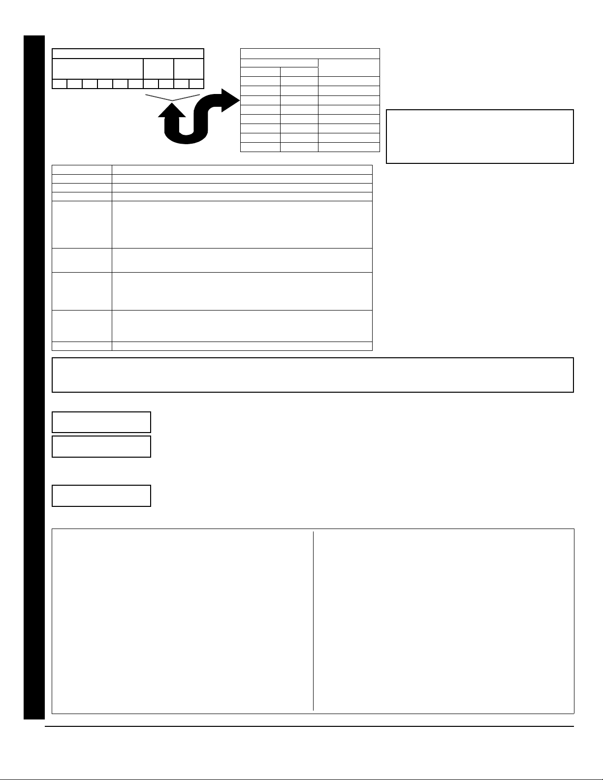
AREA OPTIONS: Area 1 and Area 2 Options
may be programmed for all 32 users.
Select the desired Area Options (Area 1-and
2) from the table shown and enter in the
remaining four boxes for each user code.
Example: Program a code of “2222” for user 02,
with area 1 options of “Arm/Disarm” and “User
Program”. Enter “2222” for a user code, “•(blank)
9” for area 1 options and “•(blank) •(blank)” for area
2 options.
Related User Options: “Enable Global Ambush
Code” (Address 1422), “Global Ambush
Code” (Address 2045) & “Enable Manager's
Mode” (Address 1421).
AREA OPTIONS EXPLANATION
Disabled User Code not active in this area.
Arm/Disarm Allows User Code to arm/disarm this area.
Arm Only Prevents User Code from disarming this area.
Service A Service Code has restricted arm/disarm rights; if an area is armed with a
Service Code, a “MONITOR ON” appears on the GEM-RP2ASe2 keypad and the area
can be disarmed with any valid User Code, including a Service Code. If the area is
armed with OTHER than a Service Code, it CANNOT be disarmed with a Service
Code. This is typically used to allow tradesmen access to premises under control
of the owner.
Access This is normally used to activate a door strike while an area is disarmed. Also
program “Access Control on PGM2 Output” (Address 0719) and “PGM2 Output
Access Control Timeout” (Address 0711).
Ambush There are two types of Ambush Codes: (1) A 2-digit code (prefix) that is entered
immediately prior to (and as part of) the regular User Code and (2) A separate and
unique User Code. Disarming with an Ambush Code will cause a silent report to be
sent to a central station. Thus, should a user be forced to disarm, he can silently signal
an emergency while appearing to be merely disarming the system.
* User Program User Program Option is enabled for Keypad 1 only, wherever it is connected (Area
1 or Area 2). To enable User Program Option for any user add 8 to the data entry
for Area 1 Option (see example). Then, User Programming can be performed only
at Keypad 1 by a user code with user program enabled.
Bypass Enable Security Bypass--Bypass is enabled only with a security code.
(Direct Entry)
Zn# 01
000000
(Direct Entry)
:0 Pt
Quick Enroll Method.
If a receiver is already installed in the panel, Napco transmitter
wireless points can be programmed automatically (“enrolled”)
using the following procedure. NOTE: The transmitter point will
be enrolled only if the signal strength is 3 or greater.
1. Enter the zone number to which the transmitter point will be
mapped.
2. Press the Bbutton to enter the Enroll Mode. The red and
green LEDs on the keypad will flash.
3. Open the loop of the point that is to be programmed (GEM-
TRANS2 only).
4. Install the transmitter battery. The keypad will beep to indicate
that the point has been successfully enrolled. Multi-point
transmitters can be mapped to successive zones
simultaneously (see example).
Example. A 2-point transmitter has the RF ID number 287613:1.
Map point 1 to Zone 6 and point 2 to Zone 9.
1. Enter the Enroll mode as described above.
2. Enter Zone “06”.
3. Open point-1 loop.
4. Install the battery. The keypad will beep once to indicate that
one point has been programmed. (Transmitter 287613:1,
point 1 will be mapped to Zone 6).
5. Enter Zone “09”.
6. Close point-1 loop and open point-2 loop.
7. Remove the transmitter battery, then re-install it. The keypad
will beep once to indicate that one point has been
programmed. (Transmitter 287613:1, point 2 is mapped to
Zone 9).
USER OPTIONS
USER CODE
(UP TO 6 DIGITS)
AREA 1
OPTIONS
AREA 2
OPTIONS
USER AREA OPTIONS
DATA ENTRIES
L R
blank(•) blank(•) Disabled
blank(•) 1 Arm/Disarm
blank(•) 2 Arm Only
blank(•) 3 Service
blank(•) 4 Access
blank(•) 5 Ambush
blank(•) Add 8 * User Program
4 blank(•) Bypass Enable
OPTION
ENABLED
GEM-RP2ASe2/GEM-K2AS--Easy Menu Driven Program Mode

LNAPCO Security Systems XGEM-P1632 Programming Instructions
Page 11
WI1148B 10/06
Keyfob Transmitters as Arm/Disarm & Control Devices
(Press Rto set cursor).
Keyfobs can be programmed as “Arm/Disarm” devices using their On/Off buttons (refer to WI752). For
each Keyfob Transmitter, enter:
The Keyfob Transmitter number (01–08). Press 01 through 08for 01-08.
Area number to which transmitter is assigned (0 to disable keyfob, 1 or 2). Press 0, 1
and 2for 0, 1 and 2, respectively.
The 6-digit RF ID # printed on the transmitter (enter all numbers and/or letters, including leading
“0”s, if any): “0” through ”9” = 0through 9; “A” = G0; “B” = G1; “C” =
G2; “D” = G3; “E” = G4and “F” = G5.
1-digit checksum number printed on the transmitter.
Aux 1 Option (see keyfob aux 1 & aux 2 options).
Aux 2 Option (see keyfob aux 1 & aux 2 options).
For Aux 1/Aux 2 Options: “0”, “1”, “2” and ”9” = 0, 1, 2and
9, respectively; “A” = G0; “B” = G1; “C” = G2and “D” =
G3.
If the Keyfob is converted for Two Button “Emergency Use” (by cutting an internal jumper), both top
or bottom buttons must be depressed to activate an alarm. In this case, the Aux-1 and Aux-2 cannot
be programmed. Press Uto save. Press the NEXT/YES button to proceed. NOTE: Keyfobs 1-8
report openings and closings as Users 25-32.
Keyfob Transmitters as Zone Input Devices
(refer to display as shown above: press the PRIOR/NO button to go backwards).
Each of the 4 keyfob buttons can be assigned to a zone. For example, On button = point 1; Off button = point 2; A1 = point 3; A2 =
point 4. Up to 32 keyfobs (using 1 button) or 16 keyfobs (using 2 buttons) or 8 keyfobs (using all 4 buttons) or any combination up to
a maximum of 32 controlled zones can be assigned, providing multiple wireless panic buttons on a system, each reporting to a
Central Station or a pager and/or annunciating on a keypad the keyfob zone number with description/location. To assign a keyfob to
a zone: program the keyfob as you would a transmitter, entering the keyfob's ID code, check sum and point number at the
appropriate zone. The “Quick Method” is not allowed. The zone may be hardwired to an electrical sensor as well as assigned to a
keyfob (either one will activate the zone alarm output). NOTE: If assigning a keyfob to a zone, the “ON/OFF” buttons on the keyfob
will no longer arm/disarm the system. The keyfob is converted to a “panic only” device.
Dealer Code
Directly enter the Dealer Code (default = 456789), including leading zeros. Use the 1through
9buttons. NOTE: Press 0for a zero. Press Uto save. Re-enter the Dealer Code to verify
the previous code. Press Uto save. Press the NEXT/YES button to proceed.
ZONE DESCRIPTIONS: GEM-RP2ASe2 cannot be used to enter Zone Descriptions. To enter Zone Descriptions, you must use the
GEM-RP1CAe2 Keypad / GEM-K1CA Keypad (See WI897) or the Napco PCD-Windows Quickloader Software.
DATA
ENTRY
AUX 1/AUX 2
OPTIONS
0 None
1 Relay Group 1 Toggle
2 Relay Group 2 Toggle
9 Keypad Panic
A Keypad Aux.
B Instant
C PGM2 Ouput Toggle
D Access on PGM2 Output
E Arm Stay
F Interior Button
(Direct Entry)
KFob01
Area
(Direct Entry)
000000
(Direct Entry)
:0 0 0
(Direct Entry)
RE-ENT
(Direct Entry)
456789
(Direct Entry)
D Code
KEYFOB ZONE ASSIGNMENT: Keyfobs can also be assigned to zones to allow multiple wireless panic buttons on one alarm
system, each reporting to a central station, a pager or having a description on the keypad that describes the person holding the
keyfob, the location where the person holding the keyfob is stationed, or the special purpose of the keyfob button being depressed.
See Keyfob Transmitters as Zone Input Devices .
GEM-RP2ASe2/GEM-K2AS--Easy Menu Driven Program Mode

XGEM-P1632 Programming Instructions LNAPCO Security Systems
Page 12 WI1148B 10/06
EXIT DEALER PROGRAM MODE: This completes the custom default program. Press the Cbutton to enter the Direct
Address Program Mode for further programming or press Conce again to end all programming and resume normal keypad
operation.
Clear Dealer Program (Erases Dealer Program)
This erases the dealer program. Use this feature to start a customized default program. Program
Data and System Status Memory is erased where Scheduled Data and Zone Descriptions are
maintained.
Access address 2285, then press the Ubutton. Data entry is not allowed. NOTE: Enter Easy Menu
Driven Program Mode to program system again.
Cold Start (Erases Entire Program)
This erases the entire program including Dealer Program by erasing Program Data, Zone Description
Data and System Status Data (similar to a new panel).
Access address 2286, then press the Ubutton. Data entry is not allowed. NOTE: Some features
(schedules) can only be programmed again with the Downloading Software.
(Direct Entry)
2285 XX
(Direct Entry)
2286 XX
CLEAR PROGRAM: Should it be necessary to create a new custom default program, (a) from the Dealer Program Mode, press
Cto enter the Address Program Mode; (b) access Location 2285 (Clear Program) or 2286 (Cold Start); (c) press Uand then
(d) press Cto exit the Dealer Program Mode. A “SYSTEM TROUBLE/E09-00 SERVICE” will occur. Press Cto silence the
keypad.
GEM-RP2ASe2/GEM-K2AS--Easy Menu Driven Program Mode

LNAPCO Security Systems XGEM-P1632 Programming Instructions
Page 13
WI1148B 10/06
GEM-RP3DGTL/GEM-K3DGTL and GEM-RP4RFC/GEM-K4RF Keypad Easy Program Menu
Enter the Default Dealer Program Code ("456789") for a new panel or enter your custom Dealer Program Code if
programmed. Press R, followed by [PRIOR/NO] repeatedly until “17” is displayed (you can scroll back by pressing
B). Press [NEXT] to enter Dealer Program Mode. For the GEM-RP3DGTL/GEM-K3DGTL (and GEM-RP4RFC/GEM-
K4RF), questions are in the form of a 2-digit number flashing in the display. Press Rto set the cursor into the next field
to answer the question. Press Ragain to scroll through each segment. Press [NEXT] to go to the next question. To
review your Easy Program Mode responses (before pressing Uto save), press Runtil the 2-digit question number flashes in the dis-
play again. If the data is correct, press Uto save. If the data is incorrect, press Rto set the cursor into the next field and again enter
your data. Note: Review your Easy Program Mode responses after the initial programming of the control, except for questions marked "For
New Panel Only". These questions set up the basic structure of the panel program ("Number of Zones in an Area", etc.) and cannot be
viewed or altered once set. To exit the Dealer Program Mode, press Ctwice to resume normal keypad operation. To return the panel
to the factory default, enter the Direct Address Program Mode, go to location 2286 and press U.
Total Number of Zones (Appears for New Panel Only)
Directly enter the total number of zones to be programmed. Valid entries are from 01 to 32. Directly
enter the total number of zones, including leading zeros. Use number buttons 1through 9.
NOTE: Press the 0button for a zero. The system is based on groups of 4 zones each (after the
first 8 zones), and will automatically round up to the next group of 4. For example, if you enter 13, it
will automatically convert this to 16 zones. Press Uto save. Press the NEXT/YES button to
proceed.
Panel Zone Doubling (New Program Only)
•To double the number of hardwired panel zones from 8 to 16, press the NEXT/YES button.
•If Panel Zone doubling is not desired, press the PRIOR/NO button.
•The 16 zones will remain EOL terminated zones, requiring Normally Closed devices only.
•Refer to Wiring Diagram and Installation Instructions for wiring instructions
Fire Zones (Appears for New Panel Only)
Enter the zone number of any Fire Zones (both 2-wire, 4-wire or wireless). Valid entries are from 01
to 32. Directly enter each zone number, including leading zeros, and press Uto save, and then
repeat for any additional zone(s). Press the NEXT/YES button to proceed.
NOTE: If you are programming a multiple Area system, enter the zone number of zones required for
Areas 1 & 2. The Direct Address Program Mode can then be used to remove zones from Area 1 and
place them in Area 2. See Zone Options.
2-Wire Fire Zones (Appears for New Panel Only)
Enter the zone number of any Fire Zones (from previous question) which are to be used with 2-wire
smoke detectors. The only valid entries are 07 and 08. Directly enter each zone number, including
leading zeros. Press Uto save, and then repeat for any additional zone. NOTE: Only zones which
have been designated as Fire Zones can be programmed as 2 Wire Fire zones. Press the NEXT/
YES button to proceed. NOTE: JP7 must be set to “2-WF” position for 2-wire fire zones 7 and 8 (refer
to Installation Instructions).
Local System or C.S. Reporting System (Appears for New Panel Only)
Press the NEXT/YES button for all zones to report; press the PRIOR/NO button for no zones to report
(LOCAL SYSTEM).
Exit/Entry Zones (Appears for New Panel Only)
Directly enter the zone numbers which are to be used as Exit/Entry zones. Valid entries are from 01
to 32. Directly enter each zone number, including leading zeros. Use number buttons 1through
9. NOTE: Press the 0button for a zero. Press Uto save and then repeat for any
additional zone(s). Press the NEXT/YES button to proceed.
NOTE: Exit/Entry Zones will have an entry delay of 30 seconds and an exit delay of 60 seconds.
R
COMPUTERIZED SECURITY SYSTEM
ARMED
STATUS
SYSTEM ARMED
01/01/97 12:00AM
12
4
3
56
7890
A
B
C
D
E
F
G
NEXT/YES
PRIOR/NO
AREA
GEMINI
ENT A1
17
INTE R IOR
BYPASS
FIRE/TBL
SYST BL
CHIME
(Press YES or NO)
06
INTERIOR BYPASS FIRE/TBL SYS TBL CHIME
(Direct Entry)
07
INTERIOR BYPASS FIRE/TBL SYS TBL CHIME
H
(Direct Entry)
05
INTERIOR BYPASS FIRE/TBL SYS TBL CHIME
H
(Direct Entry)
04
INTERIOR BYPASS FIRE/TBL SYS TBL CHIME
H
(Direct Entry)
01
INTERIOR BYPASS FIRE/TBL SYS TBL CHIME
Flashing
(Press YES or NO)
03
INTERIOR BYPASS FIRE/TBL SYS TBL CHIME
H
GEM-RP3DGTL/GEM-K3DGTL AND GEM-RP4RFC/GEM-K4RF Easy Menu Driven Program Mode

XGEM-P1632 Programming Instructions LNAPCO Security Systems
Page 14 WI1148B 10/06
Interior Zones (Appears for New Panel Only)
Directly enter the zone numbers which are to be used as Interior Zones. Valid entries are from 01
to 32. Directly enter each zone number, including leading zeros. Use number buttons 1
through 9. NOTE: Press the 0button for a zero. Press Uto save and then repeat for
any additional zone(s). Press the NEXT/YES button to proceed.
NOTE: All Interior zones will also be automatically programmed as “Exit/Entry Follower” and
"Power Up Delay" zones.
24 Hour Zones in Area 1 (New Program Only)
•Enter the zone numbers of zones to be used as 24 Hour zones.
•Valid entries are from 01 to 32. Directly enter each zone number, including leading zeros.
•Press Uto save and repeat for any additional zone(s); press the NEXT/YES button to proceed.
Chime Zones in Area 1 (New Program Only)
•Enter the zone numbers which are to be used as Chime Zones.
•Valid entries are from 01 to 32. Directly enter each zone number, including leading zeros.
•Press Uto save and then repeat for any additional zone(s), press the NEXT/YES button to proceed.
NOTE: A chime time of 2 seconds will be automatically programmed.
Chime 2 Zones in Area 1 (New Program Only)
•Enter the zone numbers which are to be used as Chime 2 Zones.
•Valid entries are from 01 to 32. Directly enter each zone number, including leading zeros.
•Press Uto save and then repeat for any additional zone(s), Press the NEXT/YES button to proceed.
NOTE: A chime time of 2 seconds will be automatically programmed.
Chime 2 zones give a distinct pulsating tone when zone is faulted.
Exit/Entry2 Zones in Area 1 (New Program Only)
•Enter the zone numbers of zones to be used as Exit/Entry zones.
•Valid entries are from 01 to 32. Directly enter each zone number, including leading zeros.
•Press Uto save and repeat for any additional zone(s); press the NEXT/YES button to proceed.
NOTE: An Exit/Entry 2 Entry Time of 30 sec. will automatically be programmed.
50 mS Loop Response Zones (New Program Only)
•Enter the zone numbers of zones to be have a 50mS loop response.
•Valid entries are from 01 to 8. Directly enter each zone number, including leading zeros.
•Press Uto save and then repeat for any additional zone(s), press the NEXT/YES button to pro-
ceed. (Note: 750mS is required for Loop Response time in UL installations). Note: Time
can also be adjusted via address 2280.
Aux Output Activated on Alarm Zones (New Program Only)
•Enter the zone numbers of zones to activate the PGM2 Output upon alarm.
•Valid entries are from 01 to 32. Directly enter each zone number, including leading zeros.
•Press Uto save and then repeat for any additional zone(s), Press the NEXT/YES button to pro-
ceed.
NOTE: A PGM2 Output Timeout of 15 Minutes will automatically be programmed.
(Direct Entry)
(Direct Entry)
14
INTERIOR BYPASS FIRE/TBL SYS TBL CHIME
H
(Direct Entry)
13
INTERIOR BYPASS FIRE/TBL SYS TBL CHIME
H
(Direct Entry)
12
INTERIOR BYPASS FIRE/TBL SYS TBL CHIME
H
(Direct Entry)
11
INTERIOR BYPASS FIRE/TBL SYS TBL CHIME
H
(Direct Entry)
09
INTERIOR BYPASS FIRE/TBL SYS TBL CHIME
H
(Direct Entry)
08
INTERIOR BYPASS FIRE/TBL SYS TBL CHIME
H
10
INTERIOR BYPASS FIRE/TBL SYS TBL CHIME
H
GEM-RP3DGTL/GEM-K3DGTL AND GEM-RP4RFC/GEM-K4RF Easy Menu Driven Program Mode

LNAPCO Security Systems XGEM-P1632 Programming Instructions
Page 15
WI1148B 10/06
Sensor Watch Zones (New Program Only)
•Enter the zone numbers of zones to be Sensor Watch zones.
•Valid entries are from 01 to 32. Directly enter each zone number, including leading zeros.
•Press Uto save and then repeat for any additional zone(s), press the NEXT/YES button to pro-
ceed.
NOTE: A Sensor Watch Time of 24 hours will automatically be programmed.
Keypad Sounder On Alarm Zones (New Program Only)
•Enter the zone numbers of all zones to activate the Keypad Sounder upon alarm.
•Valid entries are from 01 to 32. Directly enter each zone number, including leading zeros.
•Press Uto save and then repeat for any additional zone(s), press the NEXT/YES button to pro-
ceed.
Auto Bypass Re-entry Zones (New Program Only) (Not evaluated by UL)
•Enter the zone numbers of zones to be Auto Bypass Re-entry zones.
•Valid entries are from 01 to 32. Directly enter each zone number, including leading zeros.
•Press Uto save and then repeat for any additional zone(s), press the NEXT/YES button to pro-
ceed.
•Auto Bypass Re-entry Zones allow the system to be armed with the zone faulted but come
back into the system (armed) when the zone is subsequently closed.
Enable No EOLR Zones (New Program Only)
•Press the NEXT/YES button to program all zones except 24 Hr & fire zones for No End Of Line
Resistor. Press the PRIOR/NO button to continue. NOTE: Do not program this feature for UL
Installations.
Enable Telco Line Fault Test?
•Press the NEXT/YES button to enable Telco Line Fault Test.
•Press the PRIOR/NO button to continue.
NOTE: There is a preset 60 second Telco Line Fault Test Delay.
Enable Burg Output Chirp on KeyFob?
•Press the NEXT/YES button to enable Burg Output Chirp on KeyFob Arm / Disarm.
•Press the PRIOR/NO button to continue.
NOTE: The Burg Output will chirp once on Keyfob Arm and twice on Keyfob Disarm.
Enable SIA CP-01?
•Press the NEXT/YES button to enable.
•Press the PRIOR/NO button to continue.
The SIA CP-01 Features are designed to reduce the incidence of false alarms. NOTE: Do not
enable unless reporting, otherwise system trouble Fail to Communicate may occur.
(Press YES or NO)
18
INTERIOR BYPASS FIRE/TBL SYS TBL CHIME
(Press YES or NO)
21
INTERIOR BYPASS FIRE/TBL SYS TBL CHIME
(Press YES or NO)
20
INTERIOR BYPASS FIRE/TBL SYS TBL CHIME
(Press YES or NO)
19
INTERIOR BYPASS FIRE/TBL SYS TBL CHIME
(Direct Entry)
17
INTERIOR BYPASS FIRE/TBL SYS TBL CHIME
H
(Direct Entry)
16
INTERIOR BYPASS FIRE/TBL SYS TBL CHIME
H
(Direct Entry)
15
INTERIOR BYPASS FIRE/TBL SYS TBL CHIME
H
GEM-RP3DGTL/GEM-K3DGTL AND GEM-RP4RFC/GEM-K4RF Easy Menu Driven Program Mode

XGEM-P1632 Programming Instructions LNAPCO Security Systems
Page 16 WI1148B 10/06
Number of Keypads
Directly enter the total number of Keypads to be installed. Valid entries are from 01 to 07.
Directly enter the number of keypads, including leading zeros. Use number buttons 1
through 9. NOTE: Press 0for a zero. Press Uto save. Press the NEXT/YES button
to proceed.
Central Station Receiver 1 Telephone Number
Using number buttons, enter telephone number of up to 16 digits including prefix letters, if
necessary, for receiver 1. Use number buttons 1through 9for digits 1–9; press
G0for a zero and G1through G5for letters B–F, respectively.
NOTE: Pre-Dial Delay = “D”; Dial-Tone Detection = “E”. Pressing 0will produce a blank
space (•). Press Uto save. Press the NEXT/YES button to proceed. NOTE: Central Station
Receiver 2 and 3 Telephone Numbers can only be entered in Direct Address Programming. See
CS Receiver Options.
Central Station Receiver 1 Account Number
Enter an account number of up to four digits. Use number buttons 1through 9for
digits 1–9. NOTE: Press the 0button for a zero and press the G0buttons for a
blank space (•). Press Uto save. Press the NEXT/YES button to proceed. NOTE: Central
Station Receiver 2 and 3 Account Numbers can only be entered in Direct Address Programming.
See CS Reporting Options.
Central Station Receiver 1 Format
From the table below, enter the central station's receiver format. Use number buttons 1
through 9. NOTE: Press the 0button for a zero and press G0for a blank
space (•). Press G1through G4for letters B–E, respectively. Press Uto
save. Press the NEXT/YES button to proceed.
Enter User Codes (Press the (R) button to set cursor)
Enter up to 32 User Codes with User Options for each code. Refer to the tables below for available
data entries for User Options.
Press Ronce to set cursor to the User Number and enter the desired User Number. Press
Ronce again to set the cursor to the User Code. Use the number buttons 1through 9
to enter a code from 3 to 6 digits. Enter up to 6 digits (4 digits are recommended) in the first six boxes
from left to right for each user code. Valid entries are: 0-9. Note: Press 0for a zero. No blank
spaces in between; leave blank (•) any trailing boxes. If an “Ambush Prefix” (Address 0495) is entered, do not program the first two
digits of ANY User Code as the same digits entered for the “Ambush Prefix”.
If the programmed code is less than 6 digits, press Rto set the cursor to USER OPTIONS.
Refer to the tables on the next page for the available User Option data entries.
DATA ENTRY CS RECEIVER 1 FORMAT
blank(•) Ademco Slow, Silent Knight Slow
1 Sescoa, Vertex, DCI, Franklin Fast
2 Radionics Fast
3 Silent Knight Fast
4 Radionics, DCI, Franklin Slow
5 Universal High Speed
8 Radionics BFSK
DATA ENTRY CS RECEIVER 1 FORMAT
9 FBI 4/3/1
0 Radionics Modem 2
B SIA
C Ademco Point ID
D Ademco Express
E Pager
NOTE: Modem IIe is
available only in Direct
Address Programming.
Central Station Receiver 2
and 3 Formats can only be
entered in Direct Address
Programming. See CS
Receiver Options.
(Direct Entry)
27
INTERIOR BYPASS FIRE/TBL SYS TBL CHIME
(Direct Entry)
25
INTERIOR BYPASS FIRE/TBL SYS TBL CHIME
(Direct Entry)
22
INTERIOR BYPASS FIRE/TBL SYS TBL CHIME
(Direct Entry)
24
INTERIOR BYPASS FIRE/TBL SYS TBL CHIME
(Direct Entry)
26
INTERIOR BYPASS FIRE/TBL SYS TBL CHIME
8
_ H
_ 3
_ 3
GEM-RP3DGTL/GEM-K3DGTL AND GEM-RP4RFC/GEM-K4RF Easy Menu Driven Program Mode

LNAPCO Security Systems XGEM-P1632 Programming Instructions
Page 17
WI1148B 10/06
RF Transmitter Points (Press the (R) button to set cursor)
(For wireless systems only. Also see Quick Method, which follows).
For each transmitter (keyfob transmitters also), enter the zone number (01–32) to which the transmitter
will be mapped, the 6-digit RF ID#: 1-digit checksum number printed on the transmitter and box, the
point number (1 or 2); enter “9” for unsupervised (all points). NOTE: When programming the ID Code
number, “A” = G0; “B” = G1; “C” = G2; “D” = G3; “E” =
G4; “F” = G5. Press Jto save. Press NEXT (E) to proceed.
Related User Options: “Enable Global Ambush Code” (Address 1422) & “Global
Ambush Code” (Address 2045).
CODE TYPE EXPLANATION
Disabled User Code not active.
Arm/Disarm Allows User Code to arm/disarm.
Arm Only Prevents User Code from disarming.
Service A Service Code has restricted arm/disarm rights; if an area is armed with a Service Code,
a “SERVICE ON” appears on the GEM-RP2ASe2 keypad and the area can be disarmed with
any valid User Code, including a Service Code. If the area is armed with OTHER than a
Service Code, it CANNOT be disarmed with a Service Code. This is typically used to
allow tradesmen access to premises under control of the owner.
Access This is normally used to activate a door strike. Also program “Access Control on PGM2
Output” (Address 0719) and “PGM2 Output Access Control Timeout” (Address 0711).
Ambush There are two types of Ambush Codes: (1) A 2-digit code (prefix) that is entered
immediately prior to (and as part of) the regular User Code and (2) A separate and
unique User Code. Disarming with an Ambush Code will cause a silent report to be
sent to a central station. Thus, should a user be forced to disarm, he can silently signal
an emergency while appearing to be merely disarming the system.
* User Program User Program Option is enabled for Keypad 1 only, wherever it is connected. To enable
User Program Option for any user add 8 to the data entry Option (see example). Then,
User Programming can be performed only at Keypad 1 by a user code with user program
enabled.
Bypass Enable Security Bypass--Bypass is enabled only with a security code.
USER OPTIONS: Area 1 and 2 options for 32
Users:
Select the desired options from the table
shown and enter in the remaining boxes
for each user code.
Example: Program a code of “1234” for user 02,
with Area 1 options of “Arm/Disarm” and “User
Program”:
With “27” displayed in keypad window, press
R, 02(User 2), R
1234, G0G
0(User Code), 09 (User Area 1
options), 00 (User Area 2 Options), and
U(save).
Notes: (1) For User Code, press G0
for Blank Space; (2) For User Options, press
0for Blank Space.
28
INTERIOR BYPASS FIRE/TBL SYS TBL CHIME
Quick Enroll Method.
If a receiver is already installed in the panel, Napco transmitter
wireless points can be programmed automatically (“enrolled”)
using the following procedure. NOTE: The transmitter point will
be enrolled only if the signal strength is 3 or greater.
1. Enter the zone number to which the transmitter point will be
mapped.
2. Press the Bbutton to enter the Enroll Mode. The red
and green LEDs on the keypad will flash and the window
will display as shown at left.
3. Open the loop of the point that is to be programmed (GEM-
TRANS2 or GEM-TRANS4 only).
4. Install the transmitter battery. The keypad will beep to
indicate that the point has been successfully enrolled.
Multi-point transmitters can be mapped to successive
zones simultaneously (Example 1) or to selected zones
point by point (Example 2).
Example 1. A 4-point transmitter has the RF ID number
410078:1. Map the first three points to Zones 11–13,
respectively.
1. Enter the Enroll mode as described in step 2 above.
2. Enter Zone “11”.
3. Open the loops of points 1, 2 and 3.
4. Install the transmitter battery. The keypad will beep 3 times
to indicate that three points have been programmed.
Transmitter 410078:1, point 1 will be mapped to Zone 11.
Transmitter 410078:1, point 2 will be mapped to Zone 12.
Transmitter 410078:1, point 3 will be mapped to Zone 13.
The keypad will now display Zone 13, the last zone enrolled.
Example 2. A 2-point transmitter has the RF ID number
287613:1. Map point 1 to Zone 6 and point 2 to Zone 9.
1. Enter the Enroll mode as described above.
2. Enter Zone “06”.
3. Open point-1 loop.
4. Install the battery. The keypad will beep once to indicate that
one point has been programmed. (Transmitter 287613:1,
point 1 will be mapped to Zone 6).
5. Enter Zone “09”.
6. Close point-1 loop and open point-2 loop.
7. Remove the transmitter battery, then re-install it. The keypad
will beep once to indicate that one point has been
programmed. (Transmitter 287613:1, point 2 is mapped to
Zone 9).
CHANGING OR CANCELING A CODE: To change
any code, merely program over the existing code as
described above and press Uto save. Similarly, to
cancel a code, blank out each number of the code
and press Uto save. Note: Duplicate User Codes are
not allowed; therefore a duplicate Code entered in the
LCD Window will erase when Uis pressed.
USER OPTIONS
USER CODE
(UP TO 6 DIGITS)
AREA 1
OPTIONS
AREA 2
OPTIONS
USER AREA OPTIONS
DATA ENTRIES
L R
blank(•) blank(•) Disabled
blank(•) 1 Arm/Disarm
blank(•) 2 Arm Only
blank(•) 3 Service
blank(•) 4 Access
blank(•) 5 Ambush
blank(•) Add 8 * User Program
4 blank(•) Bypass Enable
OPTION
ENABLED
GEM-RP3DGTL/GEM-K3DGTL AND GEM-RP4RFC/GEM-K4RF Easy Menu Driven Program Mode

XGEM-P1632 Programming Instructions LNAPCO Security Systems
Page 18 WI1148B 10/06
Keyfob Transmitters (Press Rto set cursor).
Keyfobs can be programmed as “Arm/Disarm” devices (refer to WI752).
For each Keyfob Transmitter, enter:
The Keyfob Transmitter number (01–08).
Area number to which transmitter is assigned (1 or 2); enter 0 to disable keyfob.
The 6-digit RF ID # printed on the transmitter (enter all numbers and/or letters, including
leading “0”s, if any).
1-digit checksum number printed on the transmitter (enter all numbers and/or letters, including leading “0”s, if any).
Aux-1 Option (see keyfob aux 1 & aux 2 options).
Aux-2 Option (see keyfob aux 1 & aux 2 options).
Press Uto save. Press the NEXT/YES button to proceed.
Note: If the Keyfob is converted for Two Button “Emergency Use” (by cutting an internal
jumper), both top or bottom buttons must be depressed to activate an alarm. In this case, the
Aux-1 and Aux-2 cannot be programmed.
Keyfob Transmitters as Zone Input Devices (refer to display above: press the PRIOR/NO but-
ton to go backwards).
Each of the 4 keyfob buttons can be assigned to a zone. For example, On button = point 1; Off
button = point 2; A1 = point 3; A2 = point 4. Up to 32 keyfobs (using 1 button) or 16 keyfobs
(using 2 buttons) or 8 keyfobs (using all 4 buttons) or any combination up to a maximum of 32
controlled zones can be assigned, providing multiple wireless panic buttons on a system, each reporting to the Central Station or a
pager and/or annunciating on a keypad the keyfob zone number with description/location. To assign a keyfob to a zone: program
the keyfob as you would a transmitter, entering the keyfob's ID code, check sum and point number at the appropriate zone. The
“Quick Method” is not allowed. The zone may be hardwired to a sensor as well as assigned to a keyfob (either one will activate
the zone alarm output). NOTE: If assigning a keyfob to a zone, the “ON/OFF” buttons on the keyfob will no longer arm/disarm the
system. The keyfob is converted to a “panic only” device.
NOTE: Keyfobs 1-8 report openings and
closings as Users 25-32.
DATA
ENTRY
AUX 1/AUX 2
OPTIONS
0 None
1 Relay Group 1 Toggle
2 Relay Group 2 Toggle
9 Panic
A Auxiliary
B Instant
C PGM2 Output Toggle
D Access on PGM2
Output
E Arm Stay
F Interior Button
29
INTERIOR BYPASS FIRE/TBL SYS TBL CHIME
KEYFOB ZONE ASSIGNMENT: Keyfobs can also be assigned to zones to allow multiple wireless panic buttons on one
alarm system, each reporting to a central station, a pager or having a description on the keypad that describes the
person holding the keyfob, the location where the person holding the keyfob is stationed, or the special purpose of the
keyfob button being depressed. See the next page, Keyfob Zone Assignment.
GEM-RP3DGTL/GEM-K3DGTL AND GEM-RP4RFC/GEM-K4RF Easy Menu Driven Program Mode

LNAPCO Security Systems XGEM-P1632 Programming Instructions
Page 19
WI1148B 10/06
Dealer Code
Directly enter the Dealer Code, including leading zeros. Use the 1through 9buttons.
NOTE: Press 0for a zero. Press Uto save.
Re-enter the Dealer Code to verify the previous code. Press Uto save. Press the NEXT/YES
button to proceed. NOTE: The Dealer Code can be two or more digits (up to 6 digits).
CLEAR PROGRAM: Should it be necessary to create a new custom default program, (a) from the Dealer Program Mode, press
Cto enter the Address Program Mode; (b) access Location 2285 (Clear Program) or 2286 (Cold Start); (c) press Uand then
(d) press Cto exit the Dealer Program Mode. A System Trouble Condition will occur. Press Cto silence the keypad.
(Direct Entry)
33
INTERIOR BYPASS FIRE/TBL SYS TBL CHIME
rE
ZONE DESCRIPTIONS: GEM-K3DGTL cannot be used to enter Zone Descriptions. To enter Zone Descriptions, you must use the GEM-K1CA
Keypad or the Napco Quickloader Software.
DATE ENTRY: GEM-K3DGTL cannot be used to enter the date. To enter Date, you must use the GEM-K1CA Keypad (Version 5 or later) or the
Napco Quickloader Software.
TIME ENTRY: GEM-K3DGTL cannot be used to enter the time. To enter Time, you must use the GEM-K1CA Keypad (Version 5 or later) or the
Napco Quickloader Software.
EXIT DEALER PROGRAM MODE: This completes the custom default program. Press Cto enter the Direct Address
Program Mode for further programming or press Conce again to end all programming and resume normal keypad operation.
GEM-RP3DGTL/GEM-K3DGTL AND GEM-RP4RFC/GEM-K4RF Easy Menu Driven Program Mode

XGEM-P1632 Programming Instructions LNAPCO Security Systems
Page 20 WI1148B 10/06
This is an extension of the Dealer Program Mode. This method of programming is used in conjunction with the Keypad
Programming Worksheets that follow. Refer to these worksheets to identify the 4-digit location (address) of the feature
to be programmed. An illustrative example is provided on the next page.
KEYPAD PROGRAMMING OVERVIEW
Direct Address Programming allows you to go directly to the
address locations and change the data entries to customize your
control panel options. Whereas the Easy Menu Program Mode is a
simple quick start guide with limited options, the Direct Address
Program Mode is more flexible allowing you to change all the
options.
It consists of multiple address locations with two data entry
locations each (left and right) as shown in the adjacent diagram.
ACCESSING DIRECT ADDRESS PROGRAM MODE
LEFT DIGIT RIGHT DIGIT
3 C
DATA ENTRY
LOCATIONS
ADDRESS
LOCATIONS
0000
0000
TO
2287
HEXADECIMAL DATA:
•BLANK (•) = No Options
•1 to 9 = Entries 1 to 9
•0 = Entry of 10
•B to F = Entries 11 to 15
1. Press EEEEEE R
2. Press the PRIOR/NO (Q) button until:
"TURNON PROG Y/N" (GEM-RP2ASe2/GEM-K2AS)
--or--
"17"(GEM-RP3DGTL/GEM-K3DGTL or GEM-RP4RFC/GEM-
K4RF) appears on the keypad display.
3. Press the NEXT/YES (P) button to enter Dealer Program Mode.
(The panel and keypad version appears briefly on the keypad display).
4. Press Cto exit Easy Menu Driven Program Mode & enter
Direct Address Program Mode.
(For keypad display examples when in Program Mode, see next page).
Dealer Security Code
(Default is 456789)
DIRECT ADDRESS PROGRAM MODE
Other manuals for Gemini GEM-P1632
5
Table of contents
Other NAPCO Cell Phone manuals

NAPCO
NAPCO Gemini GEM-P816 User manual

NAPCO
NAPCO StarLink SLE Series User manual

NAPCO
NAPCO Gemini GEM-P1632 Installation manual

NAPCO
NAPCO StarLink SLE-LTEVI Series User manual

NAPCO
NAPCO StarLink SLE Series User manual

NAPCO
NAPCO StarLink Connect Series User manual

NAPCO
NAPCO StarLink SLE-LTEVI-FIRE User manual

NAPCO
NAPCO StarLink SLE-LTEV-SS User manual

NAPCO
NAPCO StarLink Full Data SL-1FD-T User manual

NAPCO
NAPCO StarLink SLE-LTEVI-FIRE User manual