NAPCO StarLink Connect Series User manual

NAPCO StarLink Fire: Getting Started Guide 1
Getting Started with NAPCO StarLink Fire Communicators
Welcome to the NAPCO StarLink series of commercial fire alarm communicators, designed to be the most reliable, cost
effective and easiest to install in the industry. The wide selection of StarLink models will ensure you have the correct com-
municator for every commercial fire application. All models meet UL864 10th edition and are NFPA 72 compliant.
This document will guide you through the entire process, from the selection of the correct communicator model for the ap-
plication, service plan selection, device activation, wiring, NOC configuration and AHJ testing of the completed installation.
To access the following information, simply click on the respective link:
Selection of the Communicator Model.
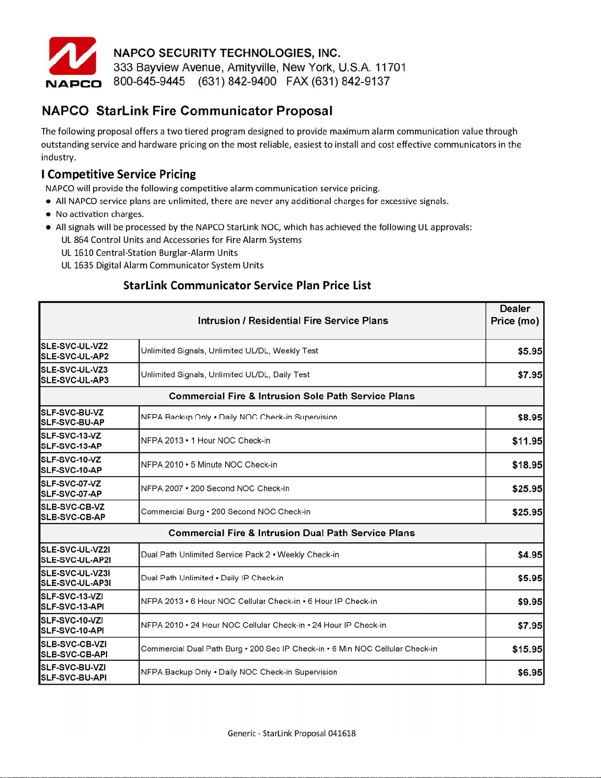
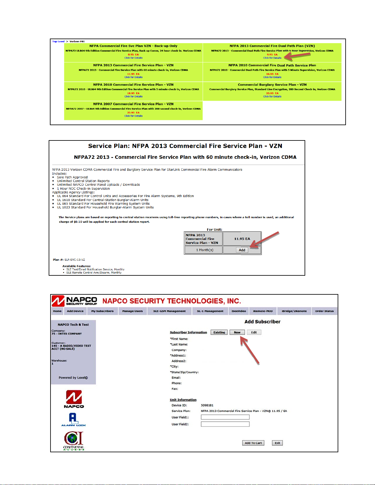
Selection of the Service Plan.
StarLink Service Plan Price List.
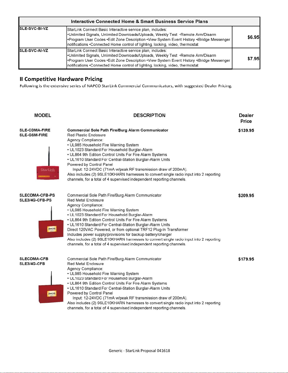
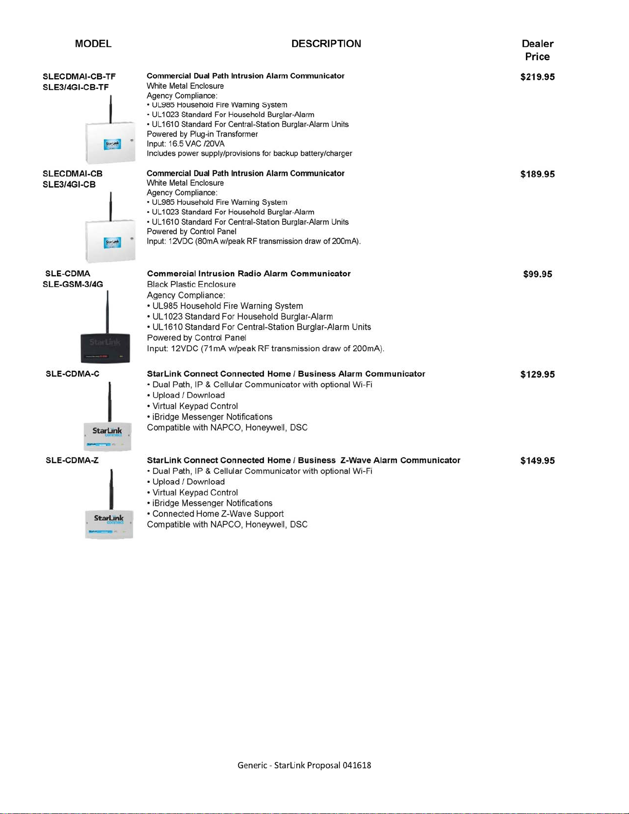
StarLink Communicator Price List.
ComNet Communicator Activation, step-by-step.
Quick Start, NOC Configuration and Communicator Wiring for Dial Capture DACT Installations.
Quick Start, NOC Configuration and Communicator Wiring for a Panel Relay Triggered Installation.
AHJ Testing of Communicator: Take the guesswork out of testing the fire alarm communicator, locate the NFPA
revision and installed communicator model for the required step by step AHJ test procedure:
Sole Path NFPA 2010 SLECDMA-CFB-PS & SLE3/4G-CFB-PS AHJ Insp. Guide
Sole Path NFPA 2013 SLECDMA-CFB-PS & SLE3/4G-CFB-PS AHJ Insp. Guide
Sole Path NFPA 2010 SLE-CDMA-FIRE - SLECDMA-CFB & SLE-GSM-FIRE - SLE3/4G-CFB AHJ Insp. Guide
Sole Path NFPA 2013 SLE-CDMA-FIRE - SLECDMA-CFB & SLE-GSM-FIRE - SLE3/4G-CFB AHJ Insp. Guide
Dual Path NFPA 2010 SLECDMAI-CFB-PS & SLE3-4GI-CFB-PS AHJ Insp. Guide
Dual Path NFPA 2013 SLECDMAI-CFB-PS & SLE3-4GI-CFB-PS AHJ Insp. Guide
Dual Path NFPA 2010 SLE-CDMAI-FIRE & SLECDMAI-CFB & GSM AHJ Insp. Guide
Dual Path NFPA 2013 SLE-CDMAI-FIRE & SLECDMAI-CFB & GSM AHJ Insp. Guide
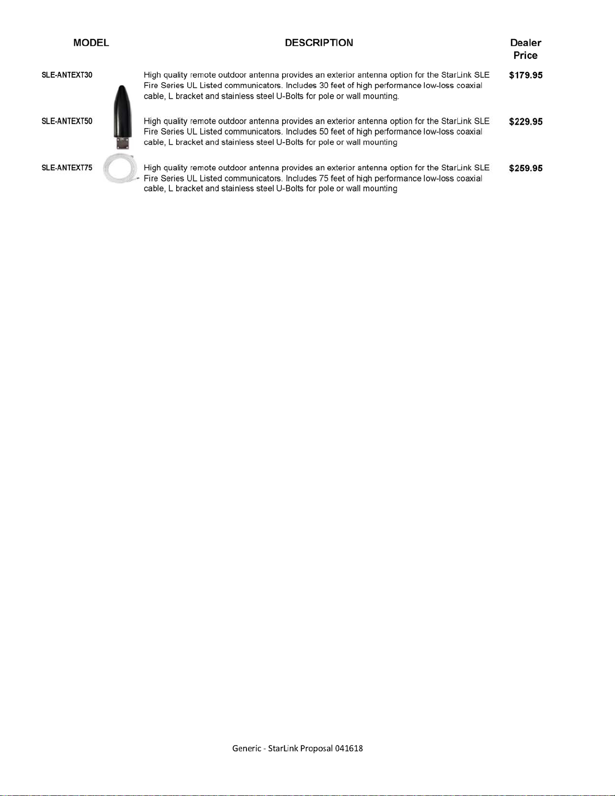
StarLink Extended Antenna Information.
For additional resources, including FAQs, CAD drawings, How-to Videos and Tech Tips, visit the
NAPCO Technical Library at http://tech.napcosecurity.com.
For NAPCO Technical Support, call 1-800-645-9440, Mon-Fri, 8:30 AM to 8:00 PM EST
© NAPCO 2018 WI2311 4/18

2 NAPCO StarLink Fire: Getting Started Guide

NAPCO StarLink Fire: Getting Started Guide 3
Getting Started...
Which model communicator should I use?
Does your FACP have available standby current of 71mA @ 24V DC ? (must be regulated power supply)
Yes Select model SLE-CDMA-FIRE / SLE-GSM-FIRE (plastic enclosure) or SLECDMA-CFB / SLE3/4G-CFB
(metal enclosure). These models are powered directly from the 24V DC AUX power provided by the FACP.
This must be regulated power; do not connect to any power outputs designated as "unregulated power". For
your standby power calcs, use 71mA (standby) and 200mA alarm (communicating). Standby backup power for
the communicator is provided by the standby batteries of the FACP during AC power failures.
No Select model SLECDMA-CFB-PS / SLE3/4G-CFB-PS (metal enclosure). These models must be directly
connected to a 120V AC dedicated circuit. Also included are provisions for a rechargeable standby battery.
When would I need a Dual Path model?
Napco offers all StarLink Fire communicator models in both Sole Path and Dual Path versions. The Sole Path models
communicate from the protected premise to the NAPCO NOC through a cellular communicator, while the Dual Path
models communicate through a cellular communicator and/or an integral internet communicator. Note that the StarLink
Fire Dual Path models have an "I" in the part number (indicating Internet). The requirement for Dual Path is typicality
determined by the municipality or the local AHJ.
Note that you may purchase and install a Dual Path communicator model, and select a Sole Path service plan. This
ensures that if Dual path compliance is required in the future, the proper communicator is already in place.
What service plan should I select?
This is typically up to your local AHJ (Authority Having Jurisdiction) who is usually the Fire Marshal of the municipality.
The AHJ will require compliance with a specific version of NFPA72 that will determine the service plan you select. If
unsure of which plan to select, contact your AHJ for guidance.
NFPA 2013 Compliance with NFPA 2013 requires service plans SLF-SVC-13-VZ or SLF-SVC-13-AP, which require
the Fire Communicator to "check-in" to the NOC every 60 minutes to ensure communicator readiness.
This plan is the most common and most municipalities have standardized on 2013. NFPA 2013 service
plans are currently selected for 80% of fire communicator activations nationwide.
NFPA 2010 Compliance with NFPA 2010 requires service plan SLF-SVC-10-VZ or SLF-SVC-10-AP, which requires
the Fire Communicator to "check-in" to the NOC every 5 minutes.
NFPA 2007 Compliance with NFPA 2007 requires service plan SLF-SVC-07-VZ or SLF-SVC-13-AP, which requires
the Fire Communicator to "check-in" to the NOC every 200 seconds.

4 NAPCO StarLink Fire: Getting Started Guide

NAPCO StarLink Fire: Getting Started Guide 5

6 NAPCO StarLink Fire: Getting Started Guide

NAPCO StarLink Fire: Getting Started Guide 7

8 NAPCO StarLink Fire: Getting Started Guide

NAPCO StarLink Fire: Getting Started Guide 9
To activate a new Remote Service device, go to www.NapcoComnet.com and log into your dealer
account. Proceed as follows:
1. Click Add Device, located at the top of the web page.
2. Click Service Plans.
3. Type the Device ID (Radio ID#) into the Unit ID field for the respective device Service Plan,
then click Go.
NAPCO Remote Services
ComNet Activation Guide
WI2113BLF 3/18
333 Bayview Avenue, Amityville, New York 11701
For Sales and Repairs, (800) 645-9445
For Technical Service, (800) 645-9440 or visit us at
http://tech.napcosecurity.com/
(Note: Technical Service is for security professionals only)
Publicly traded on NASDAQ Symbol: NSSC
© NAPCO 2018
5098181

10 NAPCO StarLink Fire: Getting Started Guide
4. Click the Click for Details text to review the details of the service plan.
5. Click Add, to add the service plan to the shopping cart.
6. Click New for a new subscriber or Existing to add the device to an existing account.
000E8F123456

NAPCO StarLink Fire: Getting Started Guide 11
7. Type the new subscriber information,
then click Add Subscriber.
8. Review the subscriber information, then
click Add to Cart.
9. Click Close if you do not want additional
features.
10. In the Shopping Cart (see below), click Process Order to complete the activation process.
John
Doe
333 Bayview Avenue
Amityville
NY 11701 USA
8006459440
00204ae11111
000E8F123456/Demo Test/2018-03-15
‒‒‒

12 NAPCO StarLink Fire: Getting Started Guide

NAPCO StarLink Fire: Getting Started Guide 13
The following summarizes the minimum required NOC programming (hƩp://NapcoNOC.com) and system wiring when connecƟng a StarLink Fire Communica-
tor to the DACT of an FACP, uƟlizing dial capture mode reporƟng. Check the installaƟon and programming instrucƟons for addiƟonal wiring and programming
opƟons. Be sure all items in the following checklist are performed:
1.Central StaƟon Receiver Telephone numbers are programmed in the "Dealer
EnteredProgramming" secƟon (see image at right):
2.ULPollFailTimeout is set (200 seconds NFPA 2007 service plan; 5 min. for
NFPA 2010 plan; 60 min. for NFPA 2013 plan or 24hr backup only):
3.(PGM1) is wired to a trouble zone in the FACP. Wire the control panel Listed
EOLR in series (terminal 3 PGM Output #1 and ground terminal #8) to a zone or
point programmed to monitor communicator troubles.
Installation Quick Start / Checklist for Fire Alarm Control Panel DACT Connect Operation
WI2162A 04/16
6 7 8 1514131211
9 10
2 3 4 51 1716
StarLink Terminals
(STARLINK HOUSING)
All connections are power limited except AC Mains,
Telco and battery terminals.
Terminals 14-17: No connections permitted.
RED
GREEN
9LE10KHARN installed in FACP:
Blue/Red normally closed relay open on trouble
Red/Black normally open relay short on alarm
To FACP Ground /
Common Terminal
(not earth ground)
To panel Telco if using
DACT reporting
+V
(12/24V) (–) PGM1 PGM2 PGM3 IN1 IN2 GND IN3 RINGTIP RTS
(R) PANEL
TX (B) PANEL
RX (G) CTS
Y
PANEL
RING (+) PANEL
TIP (–)
(Use FACP Listed
EOLR)
To FACP conventional
zone positive terminal
programmed for
communicator trouble
See
Note 3
If using addressable input for
communicator supervision,
connect Form C relay as
shown below.
– +
EOLR
EOLR
CN/C
N/O
See
Note 4
2
1
Note: All wiring diagrams and programming depicted in this guide assume the wiring between the radio and the FACPis protected byconduit.
Notes:
1. For NAPCO control panel downloading or remoteupgradingofradiofirmware, radio jumper X5_J1 must be removed.
2. Upon acƟvaƟon of the fire trouble relay (open between blue and red harness wires), a fire trouble signal will be transmiƩed to the central staƟon.
3. For StarLink models SLECDMA-CFB-PS and SLE3/4G-CFB-PS, connect to charger board terminal labeled N/O.
4. If using external relay for radio supervision, relay must be rated for radio input voltage, (12VDC, max current draw=50mA OR 24VDC, max current
draw=25mA). A listed low current relay, such as Space Age Electronics model SSU-MR-311/C/R is recommended.

14 NAPCO StarLink Fire: Getting Started Guide
The following summarizes the minimum required NOC programming (hƩp://NapcoNOC.com) and system wiring for reporƟng alarm and trouble events trig-
gered by the relays of a Fire Alarm Control Panel (FACP). Check the installaƟon and programming instrucƟons for addiƟonal wiring and programming opƟons.
Be sure all items in the following checklist are performed:
1.Central StaƟon Receiver Telephone numbers are programmed in the
"DealerEnteredProgramming" secƟon (see image at right):
2.ULPollFailTimeout is set (200 seconds NFPA 2007 service plan; 5 min.
for NFPA 2010 plan; 60 min. for NFPA 2013 plan or 24hr backup only):
3.Set CS Test Timer to 6hr or 24hr.
4.The central staƟon receiver telephone number ("Telco#forreporng
tamper/linecut/parallelinputs") and account number ("Subscriber
AccountNumber") are programmed in the Advanced tab:
Note: The central staƟon receiver telephone number and account
number must be manually entered.
5.Input 2 (IN2) and Input 3 (IN3) is set for Super-
visedFireAlarm/FireTrouble, and the desired
event number and zone numbers are pro-
grammed for Fire Alarm and Fire Trouble (also
programmed for other trouble condiƟons as
required by the local AHJ). Upon loss of power
or trouble, the FACP N/C relay must change
state from closed to open; see wiring diagram below. If necessary, IN3 may be used for addiƟonal troubles. Default Contact ID reporƟng codes: Fire
Alarm = 110 and Trouble = 373. Default 4/2 reporƟng codes: Fire Alarm = F3 and Trouble = 22.
6.(PGM1) is wired to a trouble zone in the FACP. Wire the control panel Listed EOLR in series (terminal 3 PGM Output #1 and ground terminal #8) to
a zone or point programmed to monitor radio trouble.
Notes:
1. For NAPCO control panel downloading or remoteupgradingofradiofirmware, radio jumper X5_J1 must be removed.
2. Note: Upon acƟvaƟon of the fire alarm relay (short on black and red harness wires), an alarm signal will be transmiƩed to the central staƟon.
Upon acƟvaƟon of the fire trouble relay (open between blue and red harness wires), a fire trouble signal will be transmiƩed to the central staƟon.
3. For StarLink models SLECDMA-CFB-PS and SLE3/4G-CFB-PS, connect to charger board terminal labeled N/O.
4. If using external relay for radio supervision, relay must be rated for radio input voltage, (12VDC, max current draw=50mA OR 24VDC, max current
draw=25mA). A Listed low current relay, such as Space Age Electronics model SSU-MR-311/C/R is recommended.
Installation Quick Start / Checklist for Triggering Radio Inputs from FACP Relays
WI2162A 04/16
6 7 8 1514131211
9 10
2 3 4 51 1716
StarLink Radio Terminals
(STARLINK RADIO HOUSING)
All connections are power limited except AC Mains, Telco
and battery terminals.
Terminals 14-17: No connections permitted.
RED
BLACK
9LE10KHARN installed in FACP:
Blue/Red normally closed relay open on trouble
Red/Black normally open relay short on alarm
BLUE
FACP N/C
Trouble
Relay
+V
(12/24V) (–) PGM1 PGM2 PGM3 IN1 IN2 GND IN3 RINGTIP RTS
(R) PANEL
TX (B) PANEL
RX (G) CTS
Y
PANEL
RING (+) PANEL
TIP (–)
RED
BLACK
FACP N/O
Alarm
Relay
RED
9SLE10KHARN
Wiring Harness
(Install at FACP)
CN/O** CN/O
N/C
N/C**
(Use FACP Listed
EOLR)
To FACP
conventional zone
positive terminal
programmed for
radio trouble
See
Note 3
If using addressable input for
radio supervision, connect
Form C relay as shown below.
– +
EOLR
EOLR
CN/C
N/O
See
Note 4
1
2 3
4
To FACP
Ground /Common
Terminal (not
earth ground)
RED
BLUE
FACP N/C
Trouble
Relay
RED
BLACK
FACP N/O
Alarm
Relay
RED
CN/O** C
N/C**
BLACK
9SLE10KHARN
Wiring Harness
(Install at FACP)
N/O
N/C
**FACP Trouble
Relay energized
state depicted
Note: All wiring diagrams and programming depicted in this guide assume the wiring between the radio and the FACPis protected byconduit.

NAPCO StarLink Fire: Getting Started Guide 15
333 Bayview Avenue
Amityville, New York 11701
For Sales and Repairs, (800) 645-9445
For Technical Service, (800) 645-9440 or visit us at
http://tech.napcosecurity.com/
(Note: Technical Service is for security professionals only)
Publicly traded on NASDAQ Symbol: NSSC
© NAPCO 2017
The NAPCO SLECDMA-CFB-PS Commercial Fire radio, fully compliant with the 2010 edition of NFPA 72, is ap-
proved as a fire alarm communicator. The capability of indicating and communicating signal failures to the central station
within 5 minutes of an outage allows the SLECDMA-CFB-PS to replace existing telephone lines.
The following testing guide is intended to assist with the AHJ inspection of a SLECDMA-CFB-PS Fire radio installation.
All required testing procedures are described, followed by the correct system responses. Ensure that in cases where a ra-
dio trouble output is connected to an input on the FACP, the fire control panel properly annunciates the trouble condition.
Normal LED Indications
With the SLECDMA-CFB-PS in standby mode, ensure the LEDs display as follows:
AC Failure Test
Remove radio AC power and observe the following SLEULPS-R power supply indications:
Restore radio AC power:
No Battery / Low Battery Test
Disconnect the radio battery and observe the following SLEULPS-R power supply indications:
Reconnect the radio battery:
WI2175B 1/17
StarLink™SLECDMA-CFB-PS &
SLE3/4G-CFB-PS
NFPA 2010 AHJ Inspection Guide
LED Verify this Condition Passed?
Yellow Operational LED D4 Blinks every 10 seconds (indicates normal operation).
Green RF Signal LED D3 Blinks at least 4 times (indicates minimally acceptable signal strength).
Red Trouble LED D5 OFF (indicates no trouble present).
LED
on the SLEULPS-R Verify this Condition Passed?
Yellow Trouble LED Blinks once.
Trouble Relay Output Activates after 2 hours; check for proper trouble annunciation at FACP.
LED
on the SLEULPS-R Verify this Condition Passed?
Yellow Trouble LED Blinks twice.
Trouble Relay Output Activates within 200 seconds; check for proper trouble annunciation at
FACP.
Yellow Trouble LED on the
SLEULPS-R OFF (indicates no trouble present).
Yellow Trouble LED Turns off.
Trouble Relay Output Restores; check for proper trouble restoral at FACP.
Yellow Trouble LED Turns off.
Trouble Relay Output Restores; check for proper trouble restoral at FACP.
(continued)

16 NAPCO StarLink Fire: Getting Started Guide
Signal Loss Test
This test ensures that the SLECDMA-CFB-PS will indicate a supervisory trouble condition to the FACP and cen-
tral station upon loss of signal within the required time period.
Remove the antenna and observe the following indications:
Reconnect the antenna:
Note: In cases where the radio may be located in close proximity to the cell tower, there is a possibility that the
radio may operate properly, even with the antenna removed.
LED Verify this Condition Passed?
Red Trouble LED D5 Blinks 5 times.
Yellow Trouble LED on
SLE-ULPS-R Blinks 4 times.
Trouble Relay Output on
SLE-ULPS-R Activates within 5 minutes; check for proper trouble annunciation at
FACP.
Supervisory signal E356 will be received by the central station within
5 minutes of the antenna being removed.
Red Trouble LED D5 Turns off.
Yellow Trouble LED on
SLE-ULPS-R Turns off.
Trouble Relay Output on
SLE-ULPS-R Restores; check for proper trouble restoral at FACP.
Supervisory restore signal R356 will be received by the central station
within 5 minutes of the antenna being reconnected.

NAPCO StarLink Fire: Getting Started Guide 17
333 Bayview Avenue
Amityville, New York 11701
For Sales and Repairs, (800) 645-9445
For Technical Service, (800) 645-9440 or visit us at
http://tech.napcosecurity.com/
(Note: Technical Service is for security professionals only)
Publicly traded on NASDAQ Symbol: NSSC
© NAPCO 2017
The NAPCO SLECDMA-CFB-PS Commercial Fire radio, fully compliant with the 2013 edition of NFPA 72, is ap-
proved as a fire alarm communicator. The capability of indicating and communicating signal failures to the central station
within 60 minutes of an outage allows the SLECDMA-CFB-PS to replace existing telephone lines.
The following testing guide is intended to assist with the AHJ inspection of a SLECDMA-CFB-PS Fire radio installation.
All required testing procedures are described, followed by the correct system responses. Ensure that in cases where a ra-
dio trouble output is connected to an input on the FACP, the fire control panel properly annunciates the trouble condition.
Normal LED Indications
With the SLECDMA-CFB-PS in standby mode, ensure the LEDs display as follows:
AC Failure Test
Remove radio AC power and observe the following SLEULPS-R power supply indications:
Restore radio AC power:
No Battery / Low Battery Test
Disconnect the radio battery and observe the following SLEULPS-R power supply indications:
Reconnect the radio battery:
WI2176B 1/17
StarLink™SLECDMA-CFB-PS &
SLE3/4G-CFB-PS
NFPA 2013 AHJ Inspection Guide
LED Verify this Condition Passed?
Yellow Operational LED D4 Blinks every 10 seconds (indicates normal operation).
Green RF Signal LED D3 Blinks at least 4 times (indicates minimally acceptable signal strength).
Red Trouble LED D5 OFF (indicates no trouble present).
LED
on the SLEULPS-R Verify this Condition Passed?
Yellow Trouble LED Blinks once.
Trouble Relay Output Activates after 2 hours; check for proper trouble annunciation at FACP.
LED
on the SLEULPS-R Verify this Condition Passed?
Yellow Trouble LED Blinks twice.
Trouble Relay Output Activates within 200 seconds; check for proper trouble annunciation at
FACP
Yellow Trouble LED on the
SLEULPS-R OFF (indicates no trouble present).
Yellow Trouble LED Turns off.
Trouble Relay Output Restores; check for proper trouble restoral at FACP.
Yellow Trouble LED Turns off.
Trouble Relay Output Restores; check for proper trouble restoral at FACP.
(continued)

18 NAPCO StarLink Fire: Getting Started Guide
Signal Loss Test
This test ensures that the SLECDMA-CFB-PS will indicate a supervisory trouble condition to the FACP and cen-
tral station upon loss of signal within the required time period.
Remove the antenna and observe the following indications:
Reconnect the antenna:
Note: In cases where the radio may be located in close proximity to the cell tower, there is a possibility that the
radio may operate properly, even with the antenna removed.
LED Verify this Condition Passed?
Red Trouble LED D5 Blinks 5 times.
Yellow Trouble LED on
SLE-ULPS-R Blinks 4 times.
Trouble Relay Output on
SLE-ULPS-R Activates within 60 minutes; check for proper trouble annunciation at
FACP
Supervisory signal E356 will be received by the central station within
60 minutes of the antenna being removed.
Red Trouble LED D5 Turns off.
Yellow Trouble LED on
SLE-ULPS-R Turns off.
Trouble Relay Output on
SLE-ULPS-R Restores; check for proper trouble restoral at FACP.
Supervisory restore signal R356 will be received by the central station
within 60 minutes of the antenna being reconnected.

NAPCO StarLink Fire: Getting Started Guide 19
333 Bayview Avenue
Amityville, New York 11701
For Sales and Repairs, (800) 645-9445
For Technical Service, (800) 645-9440 or visit us at
http://tech.napcosecurity.com/
(Note: Technical Service is for security professionals only)
Publicly traded on NASDAQ Symbol: NSSC
© NAPCO 2017
The NAPCO SLE-CDMA-FIRE and SLECDMA-CFB Commercial Fire radios, fully compliant with the 2010 edition of
NFPA 72, are approved as fire alarm communicators. The capability of indicating and communicating signal failures to the
central station within 5 minutes of an outage allows the SLE-CDMA-FIRE or SLECDMA-CFB to replace existing tele-
phone lines.
The following testing guide is intended to assist with the AHJ inspection of a SLE-CDMA-FIRE or SLECDMA-CFB Fire ra-
dio installation. All required testing procedures are described, followed by the correct system responses. Ensure that in
cases where a radio trouble output is connected to an input on the FACP, the fire control panel properly annunciates the
trouble condition.
Normal LED Indications
With the SLE radio in standby mode, ensure the LEDs display as follows:
AC Failure Test
No Battery / Low Battery Test
The SLE-CDMA-FIRE and SLECDMA-CFB models are powered directly from the FACP power supply; radio AC
Failure and Battery Failure tests are not required.
Signal Loss Test
This test ensures that the SLECDMA-CFB-PS will indicate a supervisory trouble condition to the FACP and cen-
tral station upon loss of signal within the required time period.
Remove the antenna and observe the following indications:
(continued)
WI2177B 1/17
StarLink™SLE-CDMA-FIRE - SLECDMA-CFB
& SLE-GSM-FIRE - SLE3/4G-CFB
NFPA 2010 AHJ Inspection Guide
LED Verify this Condition Passed?
Yellow Operational LED D4 Blinks every 10 seconds (indicates normal operation).
Green RF Signal LED D3 Blinks at least 4 times (indicates minimally acceptable signal strength).
Red Trouble LED D5 OFF (indicates no trouble present).
LED Verify this Condition Passed?
Red Trouble LED D5 Blinks 5 times.
Yellow Trouble LED on
SLE-ULPS-R Blinks 4 times.
Trouble Relay Output on
SLE-ULPS-R Activates within 5 minutes; check for proper trouble annunciation at
FACP
Supervisory signal E356 will be received by the central station within
5 minutes of the antenna being removed.
Yellow Trouble LED on the
SLEULPS-R OFF (indicates no trouble present).

20 NAPCO StarLink Fire: Getting Started Guide
Reconnect the antenna:
Note: In cases where the radio may be located in close proximity to the cell tower, there is a possibility that the
radio may operate properly, even with the antenna removed.
Red Trouble LED D5 Turns off.
Yellow Trouble LED on
SLE-ULPS-R Turns off.
Trouble Relay Output on
SLE-ULPS-R Restores; check for proper trouble restoral at FACP.
Supervisory restore signal R356 will be received by the central station
within 5 minutes of the antenna being reconnected.
Other manuals for StarLink Connect Series
1
This manual suits for next models
33
Other NAPCO Cell Phone manuals

NAPCO
NAPCO StarLink Full Data SL-1FD-T User manual

NAPCO
NAPCO StarLink SLE-LTEV-SS User manual

NAPCO
NAPCO StarLink SLE-LTEVI Series User manual

NAPCO
NAPCO StarLink SLE-LTE Commercial Series User manual

NAPCO
NAPCO Gemini GEM-P1632 Installation manual

NAPCO
NAPCO StarLink SLE Series User manual

NAPCO
NAPCO Gemini GEM-P1632 Installation manual

NAPCO
NAPCO StarLink SLE Series User manual

NAPCO
NAPCO StarLink SLE-LTEVI-FIRE User manual

NAPCO
NAPCO Gemini GEM-P816 User manual