manuals.online logo
Brands
  1. Home
  2. •
  3. Brands
  4. •
  5. NAPCO
  6. •
  7. Control Panel
  8. •
  9. NAPCO MA3000 Technical specifications

NAPCO MA3000 Technical specifications

BASIC OPERATING INSTRUCTIONS FOR THE MA3000 FIRE CONTROL PANEL
WITH THE CF3000LCD KEYPAD.
Note: Text in quotes indicates a displayed message; messages preceded and followed by asterisks indicate additional
related message(s) to follow. Buttons markings are shown in brackets ( [ ] ).
Note: This system uses a “smart” menu-driven keypad; that is,
when scrolled, the keypad will display only those options that
are relevant to the existing condtion.
STANDBY
This is the normal mode. The keypad will read “NORMAL’; no
reminders (“DISABLE”; “FIRE/TEL”; “SYS TEL”) will display; the
green AC-POWER light will be on.
FIRE ALARM
Signal deviceswill sound. The keypad will display “∗∗FIRE∗∗”,
followed by the number and description of the zone in alarm,
then “∗∗FIRE STATUS∗∗”, then “FIRE ALARM”. The “FIRE/TBL”
reminder and the ALARM light will come on.
SILENCING A FIRE ALARM
Enter code and press [SILENCE] to silence the signal devices
and keypad sounder. The keypad will display “FIRE SI-
LENCED, followed by “∗∗FIRE STATUS∗∗”, “FIRE ALARM”,
then “FIRE SILENCED”. Another alarm will sound the signals
again.
FIRE ALARM RESET
Enter code and press [INFO]. Press [NO] to continue to scroll
options or [YES] to select option.
FIRE TROUBLE
The keypad will display “FIRE TROUBLE” followed by the
number and description of the zone in trouble, then “∗∗FIRE
STATUS∗∗”, then “FIRE TROUBLE”. The “FIRE/TBL” reminder
will flash.
FIRE TROUBLE RESET
Enter code and press [INFO]. The keypad will display options
one at a time. Press [NO] to continue to scroll options or [YES]
to select option.
SUPERVISORY ALARM
The keypad will sound and display “∗∗SUPV ALARM∗∗” fol-
lowed by the number and description of the fire supervisory
zone in alarm, then “∗∗FIRE STATUS∗∗”, then “SPRINK SUPV
ALARM”. This indicates that a device designed to monitor the
fire alarm system is in alarm.
SUPERVISORY TROUBLE
The keypad will sound and display “∗∗SUPV TROUBLE∗∗”
followed by the number and description of the supervisory zone
in trouble, then “∗∗FIRE STATUS∗∗”, then “SPRINK SUPV
TRBL”.
SUPERVISORY ALARM/TROUBLE RESET
Enter code and press [INFO].The keypad will display options
one at a time. Press [NO] to continue to scroll options or [YES]
to select option.
FIRE ALARM/TROUBLE CONDITIONS
The keypad will constantly display the alarm/trouble condi-
tions still present on the system. “∗∗FIRE STATUS∗∗” will dis-
play followed by the condition(s). To determine the particular
zone(s) respansible for the condition(s), enter code and press
[INFO]. The keypad will display options one at a time. Press
[NO] to continue to scroll options or [YES] to select option.
DISABLE/ENABLE ZONE BUTTON
For installer’s use only.
ALARM TEST
Operate an initiating device. Signal devices will sound and the
keypad will display an alarm. Silence the alarm and reset the
device.
FIRE DRILL TEST
Enter code and press [INFO]. Press [NO] until “FIRE DRILL?
(YES/NO)” appears, Press [YES]. The fire signal devices
should sound. To terminate the test, enter code, then press
[SILENCE]. The keypad will display “NOT NORMAL”, indicating
that the fire bell is active.
SYSTEM TEST
To test the keypad, hold down the[*] and [3] keys simul-
taneously. The three reminders (“DISABLE”; “FIRE/TEL”; “SYS
TBL”) will display and all screen characters will appear black.
Holding the [∗] key depressed, press [3] to view different
characters on the display. Press [RESET] to terminate the test.
To test fire alarm signal devices, enter code and press
[INFO]. Press [NO] until “TEST ALARMS? (YES/NO)” appears.
Press [YES]. Fire signal devices should sound for 2 seconds.
SYSTEM TROUBLE
When a system trouble is detected, the “SYS TBL” reminder
will flash, the screen will display the system trouble, and the
keypad sounder will pulse. To acknowledge the system trouble,
enter code, then press [RESETI. The keypad will silence and
the system trouble descrIption will clear. However If the system
trouble still exists, the “SYS TEL” reminder will remain on and
the screen will display “NOT NORMAL”.
To determine the particular condition responsible for the
system trouble, enter code, then press [INFO]. Press [No] until
“DISP SYS TRBL? (YES/NO)” appears, then press [YES].
WI658C 08/99
Local Service Representative: ________________________________________________________
Address: _________________________________________________________________________
Telephone Number: ________________________________________________________________
Note: (1) Test system weekly! (2) If panel sounder is on, call for service. (3) A complete functional checkout of the control unit is required
following any programming or reprogramming. (4) This page is to be framed and mounted adjacent to the control unit.
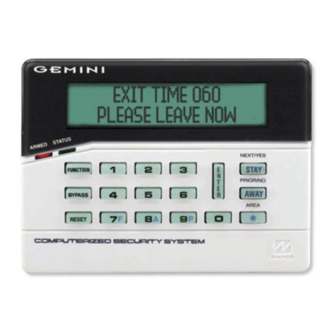
BASIC OPERATING INSTRUCTIONS FOR THE MA3000 FIRE CONTROL PANEL
WITH THE RP3000LCD KEYPAD.
Note: Text in quotes indicates a displayed message; messages preceded and followed by asterisks indicate additional
related message(s) to follow. Buttons markings are shown in brackets ( [ ] ).
STANDBY
There are two normal standby conditions for the fire system: Dis-
armed and Armed.
In Normal Disarmed Standby, the keypad will display “SYSTEM
READY” with the green STATUS light on (no Burglary Zones faulted)
or ‘ZONE FAULT” with no lights on (a Burglary Zone is faulted). No
reminders (“BYPASS”; “FIRE/TBL”; “SYS TBL”) will be on.
In Normal Armed Standby, the keypad will display “ARMED” with the
red ARMED light on. No reminders will be on. In this condition, all
Burglary Zones are protected and the entire system is normal.
FIRE ALARM
Signal devices (bells, horns, etc.) will produce a distinctive fire-alarm
sound. The keypad will display “∗∗FIRE∗∗” followed by the number and
description of the zone in alarm, then “∗∗FIRE STATUS∗∗”, then “FIRE
ALARM”. The “FIRE/TBL” reminder will be on.
BURGLARY ALARM
Signal devices (bells, horns, etc.) will produce a distinctive burglary
alarm sound. The keypad will display “∗∗ALARM∗∗” followed by the
number and description of the zone in alarm.
SILENCING A FIRE ALARM
Enter code and press [ON/OFF] to silence the signal devices, If the
signal devices have been silenced and a fire alarm condition has not
been reset, “∗∗FIRE STATUS∗∗” will display, then “FIRE SILENCED”.
Another alarm will sound the signals again.
SILENCING A BURGLARY ALARM
Enter code and press [ON/OFF) to silence signal devices. Keypad
will continue to display Burglary Zone(s) that initiated the alarm. Press
[RESET] to clear alarm memory. Another alarm will sound the signals
again.
FIRE ALARM RESET
Enter code and press [RESET]. The keypad sounder will silence;
after a brief delay, the “FIRE/TBL” reminder should clear and the
keypad display should return to “SYSTEM READY” with the green
STATUS light on (no Burglary Zones faulted) or “ZONE FAULT” with
no lights on (a Burglary Zone is faulted).
To reset the initiating device (clear smoke from the smoke detector,
etc.). enter code and press [FUNCTION] until “RESET SMOKE
DEVICES” displays, then press [YES]. If the “FIRE/TBL” reminder
does not clear, use the following procedure to identify the zones still in
an alarm condition:
1. View the menu by entering code and pressing [FUNCTION].
2. Press [FUNCTION] until “DISPLAY FIRE ALM” appears, then
press [YES].
3. Recheck the devices indicated (wait for smoke to clear from
smoke detector, etc.).
4. Repeat reset initiating device procedure.
FIRE ALARM TEST
Operate a fire alarm initiating device. Signal devices will pulse and
the keypad will display a fire alarm. Silence the alarm and reset the
system (see above).
SYSTEM TEST
Hold down the [*] & [3] keys simultaneously. The 3 reminders
(“BYPASS”; “FIRE/TBL; “SYS TBL”) should appear and all the screen
characters should appear black. Holding the [∗] key depressed, press
[3] to view different character tests on the screen display. Press
[RESET] to terminate the test.
To test the fire alarm signal devices, enter code and press
[FUNCTION] until “BELL TEST” appears. then press [YES]. Fire signal
devices should sound for 2 seconds.
TROUBLE
Call for service if the fire status condition does not clear or the “SYS
TBL” reminder is on.
SYSTEM TROUBLE
The panel will display the system trouble, the “SYS TBL” reminder
will flash, and the keypad sounder will pulse. To acknowledge the
system trouble, enter code and press [RESET]. The keypad will
silence and the system trouble description will clear. However, if the
system trouble still exists the ‘SYS TBL reminder will remain on.
To recall the system trouble, enter code and press [FUNCTION].
Press [FUNCTION] until DISPLAY SYS TBL” appears, then press
[YES].
FIRE TROUBLE
The keypad will display “∗∗FIRE TROUBLE∗∗” followed by the zone
number and description of the zone in trouble, the “FIRE/TBL”. re-
minder will flash and the keypad sounder will pulse. To reset the fire
trouble, enter code and press [RESET]. The keypad will silence and
the fire trouble description will clear. However, if the fire trouble still
exists, the display will continue to scroll “∗∗FIRE STATUS∗∗” followed
by “FIRE TROUBLE”.
To recall the fire trouble, enter code and press [FUNCTION] until
“DISPLAY FIRE TBL” appears, then press [YES].
SPRINKLER SUPERVISORY ALARM
Signal devices (bells, horns, etc.) will not sound. The keypad will
sound and display “∗∗SUPV ALARM∗∗” followed by the number and
description of the zone in alarm, then “∗∗FIRE STATUS∗∗”, then
“SPRINK ALARM”. This indicates that a device designed to monitor
the fire alarm system is in alarm. To reset a sprinkler supervisory
alarm, enter code and press [RESET]. To recall a sprinkler supervisory
zone still in alarm.
1. View the menu by entering code and pressing [FUNCTION].
2. Press [FUNCTION] until “DISPLAY FIRE ALM” appears, then
press [YES].
3. Recheck the devices indicated (reset pull station, wait for smoke
to clear from smoke detector,etc.).
4. Repeat reset initiating device procedure, at left.
SPRINKLER SUPERVISORY TROUBLE
The keypad will display “∗∗SUPV TRBL∗∗” followed by the zone
number and description of the zone in trouble. To reset the sprinkler
supervisory trouble, enter code and press [RESET] The keypad will
silence and the sprinkler supervisory trouble description will clear.
However, if the trouble still exists, “∗∗FIRE STATUS∗∗” will continue to
scroll “SPRNK SUPVTRBL”.
To recall the sprinkler supervisory trouble, enter code and press
[FUNCTION] until “DISPLAY FIRE TBL” appears, then press [YES].
FIRE ALARM/TROUBLE CONDITIONS
The keypad will constantly display the alarm/trouble conditions pre-
sent on the system. “∗∗FIRE STATUS∗∗” will display followed by the
condition(s).
DISABLE/ENABLE FIRE ZONE ([BYPASS] BUTTON)
For installers use only.
Local Service Representative: ________________________________________________________
Address: _________________________________________________________________________
Telephone Number: ________________________________________________________________
Note: (1) Test system weekly! (2) If panel sounder is on, call for service. (3) A complete functional checkout of the control unit is required
following any programming or reprogramming. (4) This page is to be framed and mounted adjacent to the control unit.

Other manuals for MA3000

1

This manual suits for next models

2

Other NAPCO Control Panel manuals

NAPCO Magnum Alert 1008 series User manual

NAPCO

NAPCO Magnum Alert 1008 series User manual

NAPCO Gemini GEM-P816 Installation manual

NAPCO

NAPCO Gemini GEM-P816 Installation manual

NAPCO Gemini GEM-P1664EX Installation manual

NAPCO

NAPCO Gemini GEM-P1664EX Installation manual

NAPCO GEMINI GEMC-255 User manual

NAPCO

NAPCO GEMINI GEMC-255 User manual

NAPCO Gemini GEM-P3200 Installation manual

NAPCO

NAPCO Gemini GEM-P3200 Installation manual

NAPCO Magnum Alert 1016e User manual

NAPCO

NAPCO Magnum Alert 1016e User manual

NAPCO Continental Access Accelaterm Manual

NAPCO

NAPCO Continental Access Accelaterm Manual

NAPCO Gemini P1632 User manual

NAPCO

NAPCO Gemini P1632 User manual

NAPCO Gemini GEM-P1632 Installation manual

NAPCO

NAPCO Gemini GEM-P1632 Installation manual

NAPCO Gemini GEM-P3200 User manual

NAPCO

NAPCO Gemini GEM-P3200 User manual

NAPCO Magnum Alert 1000e User manual

NAPCO

NAPCO Magnum Alert 1000e User manual

NAPCO Freedom F-64 Installation manual

NAPCO

NAPCO Freedom F-64 Installation manual

NAPCO Gemini GEM-X255 Installation manual

NAPCO

NAPCO Gemini GEM-X255 Installation manual

NAPCO XP-400 User manual

NAPCO

NAPCO XP-400 User manual

NAPCO Gemini GEM-P9600 Installation manual

NAPCO

NAPCO Gemini GEM-P9600 Installation manual

NAPCO MAGNUM ALERT RP1008 KEYPAD User manual

NAPCO

NAPCO MAGNUM ALERT RP1008 KEYPAD User manual

NAPCO GEM-P400 User manual

NAPCO

NAPCO GEM-P400 User manual

NAPCO Gemini GEM-P3200 Installation and operating instructions

NAPCO

NAPCO Gemini GEM-P3200 Installation and operating instructions

NAPCO Gemini GEM-P3200 User manual

NAPCO

NAPCO Gemini GEM-P3200 User manual

NAPCO Gemini GEM-P1632 User manual

NAPCO

NAPCO Gemini GEM-P1632 User manual

NAPCO GEM-P800 User manual

NAPCO

NAPCO GEM-P800 User manual

NAPCO Gemini GEM-P9600 Installation manual

NAPCO

NAPCO Gemini GEM-P9600 Installation manual

NAPCO MFA6000 User manual

NAPCO

NAPCO MFA6000 User manual

NAPCO Gemini GEM-P9600 User manual

NAPCO

NAPCO Gemini GEM-P9600 User manual

Popular Control Panel manuals by other brands

RTS KP-3016 Technical manual

RTS

RTS KP-3016 Technical manual

DUYAR DISEL Installation, maintenance and operation guide

DUYAR

DUYAR DISEL Installation, maintenance and operation guide

Lite-Puter PL-CP202 user manual

Lite-Puter

Lite-Puter PL-CP202 user manual

norbar TST Series Quick reference guide

norbar

norbar TST Series Quick reference guide

RCS UPM-431B operating instructions

RCS

RCS UPM-431B operating instructions

Frick QUANTUM LX Control Panel Installation operation & maintenance

Frick

Frick QUANTUM LX Control Panel Installation operation & maintenance

Honeywell Fire-Lite Alarms MS-9050UD manual

Honeywell

Honeywell Fire-Lite Alarms MS-9050UD manual

Tecnoalarm TP8-96 Installer manual

Tecnoalarm

Tecnoalarm TP8-96 Installer manual

Schaudt LT 500 instruction manual

Schaudt

Schaudt LT 500 instruction manual

Satel VERSA IP Installer manual

Satel

Satel VERSA IP Installer manual

Nordelettronica NE276M instruction manual

Nordelettronica

Nordelettronica NE276M instruction manual

Belden grass valley NV9646 user guide

Belden

Belden grass valley NV9646 user guide

Calira Check-Panel 210 operating instructions

Calira

Calira Check-Panel 210 operating instructions

Overland Storage SnapServer XSR 120 instructions

Overland Storage

Overland Storage SnapServer XSR 120 instructions

Sony RCP-1001 Operation manual

Sony

Sony RCP-1001 Operation manual

Beckhoff CP60 Series Installation and operating instructions

Beckhoff

Beckhoff CP60 Series Installation and operating instructions

Truma CP plus Operating and installation instructions

Truma

Truma CP plus Operating and installation instructions

Braeburn Economy Series Installer's guide

Braeburn

Braeburn Economy Series Installer's guide

manuals.online logo
manuals.online logoBrands
  • About & Mission
  • Contact us
  • Privacy Policy
  • Terms and Conditions

Copyright 2025 Manuals.Online. All Rights Reserved.