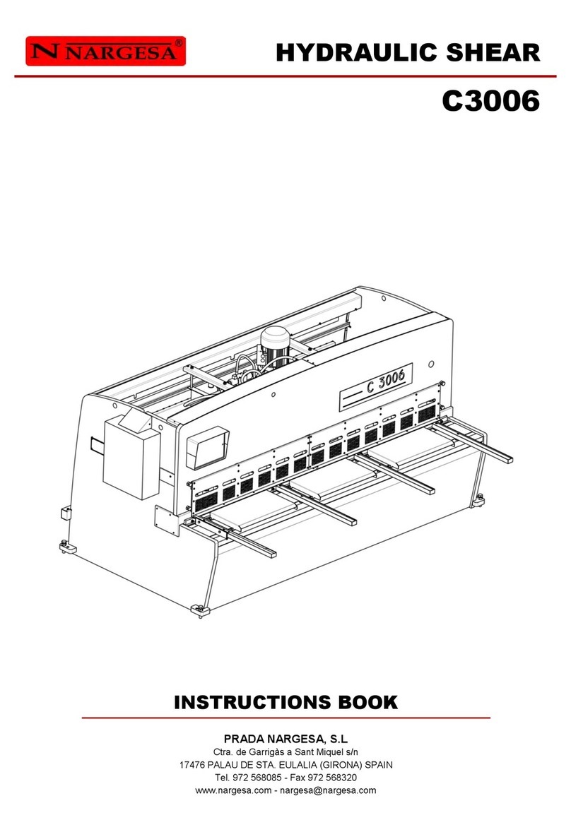
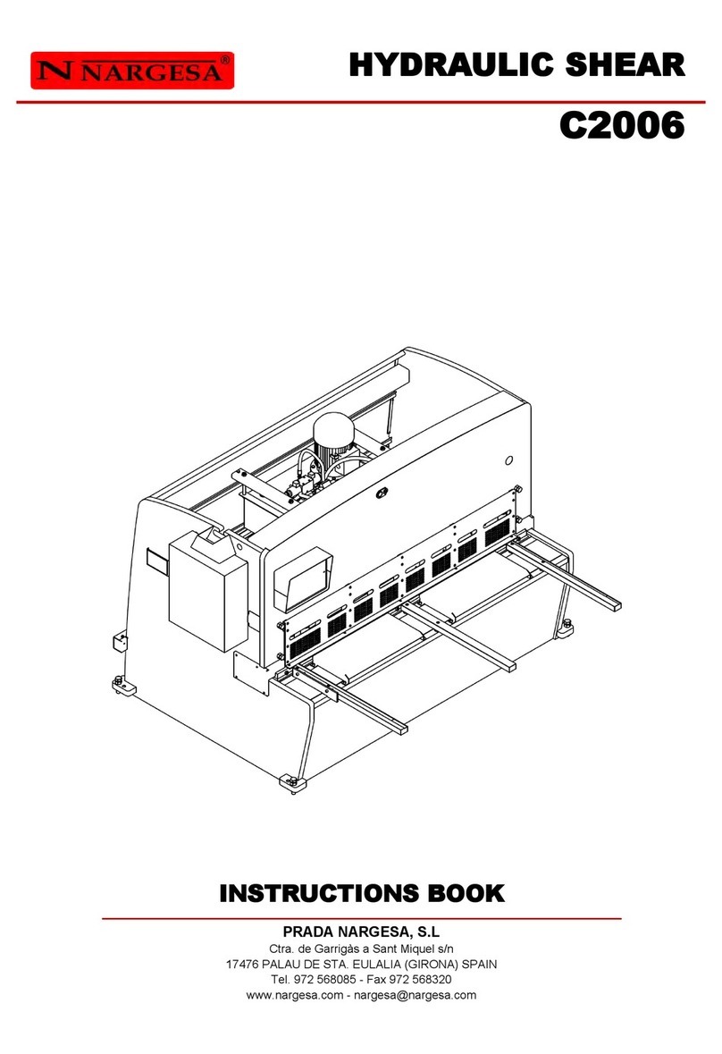
NARGESA C3006 User manual

INSTRUCTIONS BOOK
PRADA NARGESA, S.L
Ctra. de Garrigàs a Sant Miquel s/n · 17476 Palau de Santa Eulàlia (Girona) SPAIN
Tel. +34 972568085 · [email protected] · www.nargesa.com
HYDRAULIC SHEAR
C3006

Thank you for choosing our machines
www.nargesa.com

C3006 HYDRAULIC SHEAR INSTRUCTIONS BOOK 2
INDEX
1. CHARACTERISTICS OF THE MACHINE .................................................................................. 4
1.1. Identification of the machine ......................................................................................... 4
1.2. General dimensions ....................................................................................................... 4
1.3. Description of the machine ........................................................................................... 4
1.4. Identification of the machine ........................................................................................ 5
1.5. General features ............................................................................................................ 6
1.6. Description of safety devices .......................................................................................... 7
2. TRANSPORTATION AND STORAGE .................................................................................. 8
2.1. Transportation ................................................................................................................ 8
2.2. Storage conditions ........................................................................................................ 8
3. MANINTENANCE ................................................................................................................... 9
3.1. General Maintenance ..................................................................................................... 9
3.1.1. Oil change …………………………………………………………………………… 9
3.1.2. Lubrication of bolts ………………………………………………………………. 10
3.1.3. Lubrication of the guides ………………………………………………………… 10
3.1.4. Lubrication of the gauge spindles ……………………………………………….. 11
4. INSTALACINSTALLMENT AND START UP .......................................................................... 12
4.1. Location of the machine .............................................................................................. 12
4.2. Dimensions and working site ................................................................................... 12
4.3. Admissible outer conditions ……............................................................................... 13
4.4. Connection to power supply ………………………......................................................... 13
5. HANDLING BOOK ................................................................................................................. 14
5.1. Introduction ................................................................................................................. 14
5.2. Control panel …............................................................................................................. 14
5.3. Feeding of the guillotine ........................................................................................... 15
5.4. Activation of the machine ............................................................................................. 15
5.5. Gauge retraction …….................................................................................................... 18
5.6. Light .............................................................................................................................. 19
5.7. Laser ........................................................................................................................... 19
5.8. Calculator .................................................................................................................... 20
5.9. Automatic mode ........................................................................................................... 20
5.10. Program management ................................................................................................ 22
5.11. Gauge adjustment ...................................................................................................... 24
5.12. Blade adjustment ..................................................................................................... 26
5.13. Lateral length of the cut ............................................................................................. 27
5.14. General emergency .................................................................................................... 27
5.15. Photocell interruption …………................................................................................... 29
5.16. Pump thermal protection ............................................................................................ 29
C3006 HYDRAULIC SHEAR INSTRUCTIONS BOOK 3
5.17. Alarm management ................................................................................................... 30
5.18. Input/output monitoring ............................................................................................... 31
5.19. Material management ................................................................................................ 32
5.20. Import/export parameters, materials and programs ............................................ 33
5.21. Remote service …………………………………………………………………………….. 34
5.22. Touch screen calibration ……………..…………………………………………………… 36
6. WARNINGS ............................................................................................................................. 37
7. ACCESORIES .......................................................................................................................... 38
TECHNICAL ANNEXES

C3006 HYDRAULIC SHEAR INSTRUCTIONS BOOK 4
1. CHARACTERISTICS OF THE MACHINE
1.1. Identification of the machine
1.2. General dimensions
Picture 1. External dimensions of the machine
1.3. Description of the machine
The guillotine C3006, has been designed specifically for cutting metal sheets.
The manufacturer will not take any responsibility for the damages caused to the machines or the operatives
using it at any other operation different from the ones previously specified.
The C3006 is according to the European regulations and normative for the manufacturing of machinery.
PRADA NARGESA S. L is not liable for any damage that might occur due to misuse or failure by
users to comply with the safety standards.
Trademark Nargesa
Type Hydraulic shear
Model C3006

C3006 HYDRAULIC SHEAR INSTRUCTIONS BOOK 5
1.4. Identification of the machine
Laser
Commands control
Polycarbonate
Front protection
Screws to level
the machien
Lifting spot
Power motor
Safety
Photocell
Side protections
Stands for the
entrance of the
metal sheet
Rammers

C3006 HYDRAULIC SHEAR INSTRUCTIONS BOOK 6
Picture 2. Nameplate
1.5. General features
Engine power 9,2 KW / 12 CV
Three-phased tension 230 / 400 V
Cutting Capacity: mild steel 6 mm
Cutting capacity: stailess steel 4 mm
Nº of hammers 15 units
Cutting length 3030 mm
Neck 173 mm
Gauge displacement 700 mm
Strokes per minute 12 strokes
Position accuracy and repeatibility +/- 0,1 mm
Dimensions 3865x2457x1816 mm
Weight 7500 Kg

C3006 HYDRAULIC SHEAR INSTRUCTIONS BOOK 7
Front protection to save Access
to the cutting blade.
ResBack protection
of the top belts.
Lateral protection to save access to
the cutting blade.
Protection covers must not be removed to do the maintenance works. This job must be carried out by
highly qualified technicians. PRADA NARGESA will not accept any responsibility for the damages cau-
sed by not bearing in mind to what has been previously exposed on this book.
1.6. Description of safety devices
The fixed safety devices the guillotine C3006 has are lateral to avoid any handling, the front protection
avoids from acceding to the rammers side, Protections in the back side of the machine covering the belts
and pulley of the back top, the outet ramp for the material and the upper protection cover of the piston
moveable part.
Picture 3. Safety devices

C3006 HYDRAULIC SHEAR INSTRUCTIONS BOOK 8
2. TRANSPORTATION AND STORAGE
2.1. Transportation
The lifting of the machine will be carried out by a crane, using the clamping points indicated for that. The
machine will be never lifted by any other side but the indicated one.
Picture 4. Transportation of the machine
2.2. Storage conditions
The machine will not be stored in a place that hasn’t got the following requirements:
* Humidity between 30% and 95% without water condensation.
* Temperature from -25 to 55ºC or 75ºC for a length of time not exceeding 24h (these must be considered
storage conditions)
* It is advisable not to pile up machines or heavy objects on top of it

C3006 HYDRAULIC SHEAR INSTRUCTIONS BOOK 9
WARNING: Stop the machine to make the maintenance.
3. MAINTENACNE
3.1. General maintenance
The maintenance of the Shear implies four operations:
- Oil change
- Lubrication of bolts
- Lubrication of the guides
- Lubrication of the gauge spindles
3.1.1. Oil change
The oil container level must be checked every 1000 hours of work.
The oil level sight-glass is located at the side of the tank. If oil needs to be added, fill until the sight-glass is
completely full.
Replace the hydraulic oil container every 4000 hours of work or 60 months.
Container capacity: 96 liters.
Oil: CEPSA HYDRAULIC HM 68
Once the oil has been changed, it is necessary to start up the machine and activate the pedal in
intermittence by increasing the pressure time gradually until the circuit is full.
Drain plug
Oil dipstick
Oil level sight-glass

C3006 HYDRAULIC SHEAR INSTRUCTIONS BOOK 10
3.1.2. Lubrication of bolts
To carry out the maintenance in the later grease points of the machine, we put the folding group down to its
lowest point. We stop the machine and proceed to the lubrication in the indicated points.
Grease up the bolts periodically according to the level of use.
If it is a steady and daily use, they must be greased avery month.
Rear view of the machine
3.1.3. Lubrication of the guides
In order to attain the maintenance in the lateral lubrication points of the machine, we raise the folding group
to its highest point. We stop the machine and proceed to the lubricate the indicated parts.
Lubricate all guides greasers every month.
Side view of the machine

C3006 HYDRAULIC SHEAR INSTRUCTIONS BOOK 11
3.1.4. Lubrication of the gauge spindles
To lubricate the gauge spindles, we place it in its position farthest from the folding group. We stop the
machine and proceed to lubricate the 2 spindles and the 2 guides. We put the machine in gear and
place the gauge at its minimum height, then move it to its maximum height. Repeat these movements 2 or
3 times, until the grease covers the spindles uniformly.
Lubricate the top spindles weekly with grease or oil.
Lower view of the machine

C3006 HYDRAULIC SHEAR INSTRUCTIONS BOOK 12
4. INSTALLMENT AND START UP
4.1. Location of the machine
The machine will be placed properly so that it doesn’t have to be moved, in case this was not possible then
it is necessary to follow the rules described in the Transport section. It muts be placed on a flat and levelled
surface to avoid vibrations and any sort of movement while it’s performing. It is possible to level the
machine by using the screws at the bottom of the machine, at each corner.
Picture 5. Anchor points of the machine
4.2. Dimensions and working site
The dimensions of the machine are to be considered when the machine is put down, as well as the
operative working zone and the possible different sizes of the part to be worked.
The machine will be only used by one operative, who will be located at the front side of the machine and
never in a lateral of it since he has to keep control over the whole set of the machine, moreover the main
prtection devices are designed for th efrontal use of it.
Picture 6. Working site

C3006 HYDRAULIC SHEAR INSTRUCTIONS BOOK 13
IMPORTANT
This machine must be connected to a power supply with ground wire.
Triangle figure
For voltage 230V
Star figure
(Default)
For voltage 400V
4.3. Admisible outer conditions
It is advisable to work under the following atmospheric conditions:
- Room temperature between +5 °C and +40 ºC without exceeding an average temperature of +35 °C
within 24 hrs
- Humidity between 30% and 90% without water condensation
4.4 Connection to power supply
The C2006 shears are equipped with two three-phase 230/400 V motors: a 0.37 kW motor for the gauge,
and a 5.5 kW star-connected motor which requires a single 240V or 400V power supply. If the line voltage
is not as indicated, then the motor coil connection and the gauge motor variable frequency drive (VFD) con-
nection shall be changed. The gauge VFD is NOT A MULTI-VOLTAGE VFD, so if the voltage needs to be
changed, then the VFD should be replaced accordingly.
Picture 7. Change of engine connections

C3006 HYDRAULIC SHEAR INSTRUCTIONS BOOK 14
5. HANDLING BOOK
5.1. Introduction
This manual is designed for the user of the Guillotine C3006, since it has got important information about
the use of it and the peculiar features of the machine. Therefore it is advisable to follow step by step the
points detailed in this book so a good understanding of its performance could be achieved.
5.2. Control panel

C3006 HYDRAULIC SHEAR INSTRUCTIONS BOOK 15
5.3. Feeding of the guillotine
In order to power on the machine, it is enough jus by set the Go switch in the position o Connected. Then it
will show up al abel on screen as the one below:
Picture 8. Message of activation of the machine
Right now the machine is in a StandBy mode, it happens when it is activated but in rest position awaiting
any command the user orders.
5.4. Activating the machine
Press the reset button located in the electrical panel. This reset button must be pressed each time the
machine is turned on, and after an emergency stop has been initiated by the photocell or by the emergency
stop button.
Once the shears have started up and are in Stand-by mode, they are activated following the steps below in
order to start operations.
To proceed properly press . If the power source has recently been connected, the X and Y axes need
to be synchronised by pressing .

C3006 HYDRAULIC SHEAR INSTRUCTIONS BOOK 16
The machine will automatically synchronise the axes, after which the previous message disappears and the
following is displayed:
The following message will appear once the Homing cycle has finalised.
Cuts can be done manually from this point on by simply entering the information on the required cut. To
input the cut measurements, press the corresponding button and the following screen will appear.

C3006 HYDRAULIC SHEAR INSTRUCTIONS BOOK 17
Enter the gauge dimensions required using the number keys and then press . Next, follow
the same procedure to enter the cut length, material and thickness data and press . The machine will
then position the X-axis at the required location and the following screen will appear.
The operational system (continuous or single) can also be selected during the manual mode, as can be
observed in the previous image. The manual mode is selected by default.
The mode can be changed simply by pressing
The single operational mode works in the following way:
The blade is lowered while the operator presses down on the pedal. If the pedal is released, the blade
reverses and is raised until it reaches the upper rest position.
To cut a sheet in this operational mode, the pedal is pressed down until the blade moves to the lowest
position of the vertical cut. Once in this position, the sheet has been cut and the blade has reached the
base. However, the blade will not be raised until the operator releases the pedal. If the operator releases
the pedal, the blade will move vertically until it reaches the upper rest position.

C3006 HYDRAULIC SHEAR INSTRUCTIONS BOOK 18
The continuous operational mode works in the following way:
The pedal can be pressed and released in this operational mode. Once the pedal is pressed, the blade
moves to the lower vertical position, cutting the sheet. It is then raised automatically until it reaches the
upper rest position. The blade will stay in this position until the pedal is pressed again. If various cuts need
to be made at the same position, simply press the pedal and keep it pressed as long as required. In this
case, the cuts will be made sequentially, and the operator simply enters the sheets to be cut into the
machine.
The cut counter will increase by one each time the pedal is pressed, or each time the shear blade makes a
cut and returns to the upper position if operating in continuous mode.
5.5. Gauge retraction
The gauge retraction is mainly used to prevent the sheets from being damaged when they are cut. This
function can be activated by pressing . The image will change to white, indicating that the function
has been enabled. The function is disabled by pressing (X) again, and the image will go back to being
transparent.
Once activated, the machine will behave as follows:
After entering all the cut data and activating this function.
The gauge retraction can be enabled in both single and continuous mode.

C3006 HYDRAULIC SHEAR INSTRUCTIONS BOOK 19
The hold-down plates are lowered by pressing the machine pedal. Once the sheet is fixed in place between
the hold-down plates and the machine table, the gauge will retract a few millimetres. Next, the blade is
lowered and cuts the sheet. In this way the sheet is not subjected to unnecessary friction during the cutting
operations and the sheet can be released so it can fall to the extraction ramp by gravity. Once the cut has
been made, the machine will order the blade and the hold-down plates to be raised. Once the blade is in
the rest position, the gauge will automatically return to the programmed position.
This function can be enabled or disabled in both the manual (single and continuous) and automatic modes.
5.6. Light
The cutting area has an LED light to significantly improve visibility when operating the machine.
Press the button to turn it on.
The light bulb icon is activated when doing so, as shown in the following screen shot.
Press the button to turn the light off.
5.7. Laser
The laser line is activated by pressing . The laser light is turned on and generates a laser cutting line.
The laser is very useful for cutting parts that are not square, or when making cuts that do not reach the end
position.
Press the button to turn the laser off.
Other manuals for C3006
1
Table of contents
Other NARGESA Power Tools manuals

NARGESA
NARGESA MX340G User manual

NARGESA
NARGESA MX340G User manual

NARGESA
NARGESA MC400 User manual

NARGESA
NARGESA C2006 User manual

NARGESA
NARGESA C3006 User manual

NARGESA
NARGESA C2006 User manual

NARGESA
NARGESA MP3003 CNC User manual

NARGESA
NARGESA MP3003 CNC User manual

NARGESA
NARGESA MP1400 CNC User manual