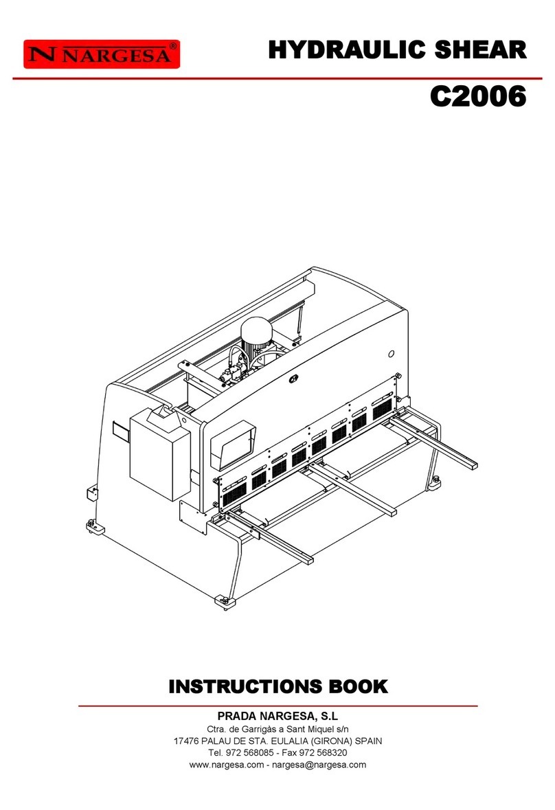
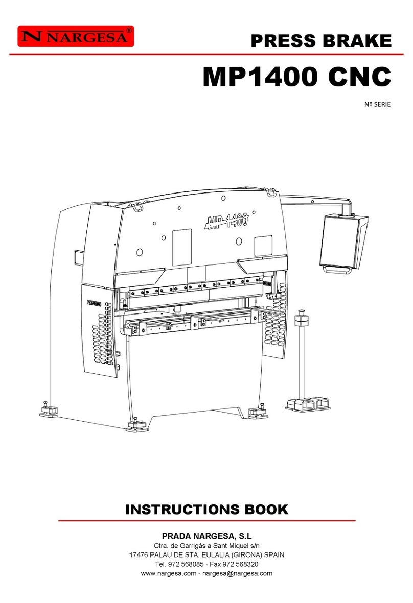
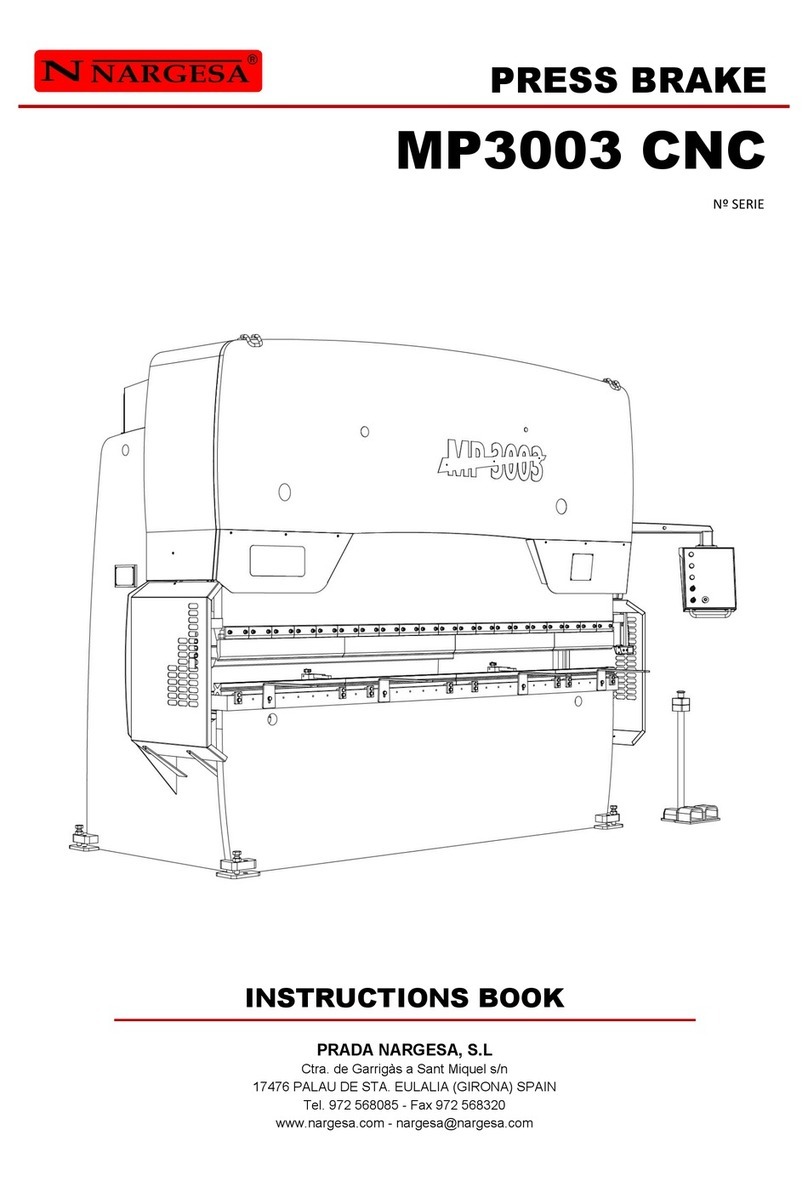
NARGESA MP3003 CNC User manual

INSTRUCTIONS BOOK
PRADA NARGESA, S.L
Ctra. de Garrigàs a Sant Miquel s/n
17476 PALAU DE STA. EULALIA (GIRONA) SPAIN
Tel. 972 568085 - Fax 972 568320
PRESS BRAKE
MP3003 CNC

Thank you for choosing our machines
www.nargesa.com

INSTRUCTIONS BOOK PRESS BRAKE MP3003 CNC 3
INDEX
1. CHARACTERISTICS OF THE MACHINE ............................................................................... 4
1.1. General dimensions .................................................................................................... 4
1.2. Description of the machine .......................................................................................... 4
1.3. Identification of the machine ....................................................................................... 5
1.4. General features ……………….…............................................................................... 6
1.5. Accessories ................................................................................................................. 6
1.5.1. Description of accessories ............................................................................. 6
1.5.2. Tooling ........................................................................................................... 7
1.6. Description of safety devices ...................................................................................... 8
2. TRANSPORTATION AND STORAGE .................................................................................... 9
2.1. Transportation ............................................................................................................. 9
2.2. Storage conditions ………………................................................................................. 9
3. MANINTENANCE .................................................................................................................. 10
3.1. General Maintenance ................................................................................................ 10
4. INSTALLMENT AND START UP .......................................................................................... 11
4.1. Location of the machine ............................................................................................ 11
4.2. Dimensions and working site …................................................................................. 11
4.3. Admissible outer conditions ...................................................................................... 11
4.4. Connection to power supply …………....................................................................... 12
5. ADJUSTMENT OF THE BACK GAUGE HANDLES ............................................................. 13
6. FOLDING GROUP REGULATION ........................................................................................ 15
7. WARNINGS …………………………..……………………………………………………….…….. 16
ANNEX 1. SOFTWARE ESA S630
ANNEX 2. TECHNICAL FEATURES
ANNEX 3. LASER DEVICES
INSTRUCTIONS BOOK PRESS BRAKE MP3003 CNC 4
1. CHARACTERISTICS OF THE MACHINE
1.1. General dimensions
1.2. Description of the machine
The MP3003CNC press brake, is designed specifically for folding sheet in different degrees, any
application other than specified above, exonerates the manufacturer from any responsibility for the damage
to the machine or the people who use it.
The MP3003CNC is according to the European standards and directives for the manufacturing of
industrial Machinery.

INSTRUCTIONS BOOK PRESS BRAKE MP3003 CNC 5
Electric motor
Hydraulic container
Oil emptying cap
1.3. Identificación de la máquina
Screws to level
the machine
Punch
Back gauge handles
Die
Die-holder
Control panel
Lateral protection
Sliding arms
Laser

INSTRUCTIONS BOOK PRESS BRAKE MP3003 CNC 6
1.4. General features
- Motor 9,5 Kw (12CV) at 1400 r.p.m.
- Intensity of 19 A at 400 V / 32 A at 230 V
- Pump 22 l./m.
- Deposit of 100 liters.
- Double acting piston (120 Tm).
- Pressure of the hydraulic pump 225 Kg./cm2
- Total weight 9100 Kg.
- Cleavage of 320 mm.
- Inner folding lenght 2700.
- Total folding lenght 3125 mm.
- Total displacement of top 600 mm.
- Maximum punch displacement 160 mm.
1.5. Accessoires
1.5.1. Description des accessoires
Le poinçon et la matrice sont traités, ce qui assure leur fiabilité et leur résistance pour un usage normal.
Les matrices possèdent plusieurs ouvertures pour les différentes épaisseurs de tôle et rayons de pli.

INSTRUCTIONS BOOK PRESS BRAKE MP3003 CNC 7
1.5.2. Tooling
The press brake MP3003CNC, has been designed for the use with “V” dies, punch and die holder.
Other dies with upper V’s seccioned punches and press brake anvils can be also used. Please ask the
manufacturer.
Punch
Die
Die holder

INSTRUCTIONS BOOK PRESS BRAKE MP3003 CNC 8
1.6. Description of safety devices
Fixed safety devices consisting of CNC press brake MP3003CNC are the side shields to prevent manipula-
tion of tooling on the sides and guards at the rear of the machine covering the belts and pulleys of the rear
gauge.
You can not remove the protective caps unless it is for maintenance and it should be carried out by techni-
cally trained personnel. PRADA NARGESA will not responsible for damage caused by not adhering to the
afore mention instructions.
Left top side
protection
Front protection of
the connecting rods
Left top side
protection
Right side protection
Front protection of
the connecting rods
Left side protection
Lower rear
protection
Left side
protection

INSTRUCTIONS BOOK PRESS BRAKE MP3003 CNC 9
2. TRANSPORTATION AND STORAGE
2.1. Transportation
Lifting should be performed by a crane, on the marking point to that end anchorage. The machine will never
rise by anywhere else other than the specified and provided the two points of the front of the machine will
be used because the weight is found mostly in the front so we will make the machine remain in a horizontal
line when raised.
2.2. Storage conditions
Press brake will not be never stored in a place where the following conditions are not settled:
* Humidity between 30% and 95% non-condensing.
* Temperature -25 to 55 ° C or 75 ° C for periods not exceeding 24 hours (remember that these
temperatures are in storage)
* It is advisable not to stack heavy objects on the machines.
* Do not disassemble for storage.
Lifting points to be
raised by a crane
Lifting points to be
raised by a crane

INSTRUCTIONS BOOK PRESS BRAKE MP3003 CNC 10
3. MAINTENANCE
3.1. General maintenance
At the top of the tank there is the level sightglass. In the absence of oil, fill up to the mark of the peephole.
- Every 1000 hours of use, check the oil level in the tank.
- Replace oil every 4,000 hours of work.
Oil Type: SIL POWER HV-46
WARNING
Stop the machine in order to carry out the maintenance of the machine. In case of replacement of the oil,
start the engine and depress the flashing time increasing the pressure gradually until the circuit is
complete.
- Grease the boulders fixing rods and piston periodically depending on use.
- If the use is daily and continuous, grease each month.
- Grease all guide fittings monthly.
- Check the oil level of the machine.
Filling cap
Oil level sight glass
Emptying cap

INSTRUCTIONS BOOK PRESS BRAKE MP3003 CNC 11
4. INSTALLMENT AND START UP
4.1 Location of the machine
It is advisable to locate the machine properly to avoid having to move it; otherwise it would be required to
follow the guidelines outlined in the transport section (# 2). It should be placed on a flat, level surface to
prevent vibration and movement during folding operations. It is possible to level the machine by screws at
the base of the machine one at each corner.
4.2 Dimensions and working site
When the machine is placed it must be taken into account its size, the workspace of the operator and the
possible lengths of the workpiece.
The machine can be used by a single operator, which must be placed frontally to the machine, never in a
side area since he should control the whole machine and also the main protections are designed for the front
use of it.
4.3 Admissible outer conditions
Ambient temperature between +5 º C and +50 º C without exceeding an average temperature of +45 º C 24h
Humidity between 30% and 90% non-condensing.

INSTRUCTIONS BOOK PRESS BRAKE MP3003 CNC 12
Triangle shape
For tension 230V
Star shape
(preset)
For tension 400V
4.4. Connection to power supply
IMPORTANT: This machine must be connected to a 400V outlet with a neutral earthing contact as
well.
The MP3003CNC, is equipped with a three-phase motor 230V / 400V star connected 9,5 Kw for connection
to a 400V power supply. It must be connected to a single power supply with the power source indicated. If
the line voltage is not the one indicated it will be necessary to proceed to change the connection of the
bobins of the motor of the hydraulic unit as follows:
The gauge activation is done by a servomotor which does not require any action when making a tensión
change from 400v to 230v or the other way around.
The inverter configuration will have to be modified as well, as indicated in the following pictures:
Configuration
400V
Configuration
230V

INSTRUCTIONS BOOK PRESS BRAKE MP3003 CNC 13
5. ADJUSTMENT OF THE BACK GAUGE HANDLES
When it becomes necessary to change the press brake gauge needles position, it will be done by an
activation bar provided for such operation and from the machine front side.
It is completely forbidden to carry out this operation without the activation bar.
In order to proceed with the movement of the needles, we insert the activation bar in the existing slot there
in the needles support.
Activation bar
Activation bar slot

INSTRUCTIONS BOOK PRESS BRAKE MP3003 CNC 14
WARNING: Make sure we have removed the lever before starting up the press brake again.
We raise the lever, releasing the needle support and we can move the needle toa new desired position.
We lower the lever and the needle will remain fixed in the new position.
We take the lever off and we have the gauge ready to be used again.

INSTRUCTIONS BOOK PRESS BRAKE MP3003 CNC 15
6. FOLDING GROUP REGULATION
Because of continuous use of the press brake it may happen that the machine does not make the same
bending angle on the right side than on the left side.
When this happens it is necessary to scale this part by using a lever on the left of the machine and follo-
wing the steps below:
• Prepare a few metal sheets with dimensions of 100x60x2 mm thickness.
• We removed the left frontal protection to expose the regulation lever.
• We place the die with the 16 "V" which is corresponding to a sheet 2mm thickness..
• We adjust the machine to make a folding operation wider than 90º. 120º is a suitable angle to observe
differences.
• We place a plate at each end of the die, respecting both are at the same distance from the end and the
bending length is the same.
• We make a folding operation with the sheets and compare one another, taking into account which is
which. If we see that the plate on the left is more open than the one at the right, then we must lower the
lever to force the ram down and close the angle. Otherwise it will be necessary to lift the lever to force the
ram up and open the angle.
• We loosen the fixing screw, move the lever, then we press the lever fixing screw and re-check.
• Repeat the above operations after each test as several attempts are often necessary before getting the
optimum position.
• Once the Folding group (Tranche) has been adjusted, fasten the fixation screw to fix the lever and pro-
ceed to the assembly of the cover sheets.
CAUTION
Never move the adjustment lever while the folding group is forcing against the die.
Adjustment lever
Fixing screw

INSTRUCTIONS BOOK PRESS BRAKE MP3003 CNC 16
7. WARNINGS
Do not manipulate components of the machine while it’s running.
Do not use the machine for any other purposes but the ones described in this manual
Use gloves for handling machine components during the folding process .
Wear safety googles and protective boots approved by the EC.
Hold the material at the ends, never by the part of the fold .
Do not work without the protections fitted to the machine.
Maintain a safe distance between the machine and the operator during the time the machine is running.
Do not use any other tooling but the ones supplied by NARGESA.
The dies that may be coupled to the machine must always be set and fixed.
In case of accident by negligence of the operator, for not following the safety and operating standards set
out in the manual, NARGESA SL will not accept any responsibility.
Bear in mind the obligation for all operators working with the machine to wear goggles, gloves and safety
shoes.
Description of the marks on the machine. It’s marked on the front with the following hazard symbols.

WARRANTY REGISTRATION
1. Among www.nargesa.com on our site
2. Select the menu Warranty Registraon
3. Complete the form with your details and press Send
4. The window Message Sent conrms your data has been successfully sent to Prada
Nargesa SL. Your machine has been registered and has a warranty of three years in
total.

Annex 1
Software ESA S630


ANEXO 1. SOFTWARE ESA S630 A2
SUMMARY
Notes ……………………………………………………….………………………………………… 3
1. MACHINE SETUP ………………………....…………………………...……………………….. 8
1.1. Ram reference …………………...………………………………...…………………… 8
1.2. Back-gauges axes reference ………………………………...……………………….. 8
2. PUNCHES AND DIES SETUP ………………………..……………………………………….. 9
2.1. Punches and dies list ……………..…………………………...………………………. 9
2.1.1. How to enter a new punch ……….…………………...……………………. 12
2.1.2. Punches to draw …………………………………...……………………… 13
2.1.3. Pre-set punches ……………...…………………………………………….. 17
2.2. How to enter a new die …………..…………………………...……………………… 18
2.2.1. Dies to draw ………………………………………...……………………….. 19
2.2.2. Pre-set dies …………………...……………….…………………………….. 24
3. PROGRAMMING ……….………………………………………..…………………………….. 25
3.1. List of programs ……………………………………...……………………………….. 25
3.2. Entering a numeric program ……………………………………..………………….. 28
3.3. Entering a graphic program (Optional in the S630 model) …………..………… 33
3.4. Automatic calculation of the bending sequence (Oprional in the S630 model) ... 39
3.5. Manual calculation of the bending sequence ……………………………………. 42
3.6. How to bend a box …………….……………………………………………………… 44
3.7. Work data ……………..……………………………………………………………….. 44
3.8. Execution of a program in automatic mode ……………...………………………… 44
3.9. Selection of the DIN formula to calculate the stretch ……………………………. 48
Other manuals for MP3003 CNC
1
Table of contents
Other NARGESA Power Tools manuals

NARGESA
NARGESA MX340G User manual

NARGESA
NARGESA C2006 User manual

NARGESA
NARGESA C3006 User manual

NARGESA
NARGESA MP3003 CNC User manual

NARGESA
NARGESA C2006 User manual

NARGESA
NARGESA MP1400 CNC User manual

NARGESA
NARGESA C3006 User manual

NARGESA
NARGESA MC400 User manual

NARGESA
NARGESA MX340G User manual