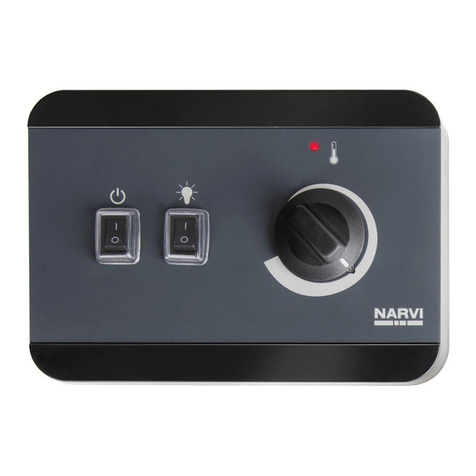
NARVI IR-IC1 User manual

narvi.fi
for 2 full-spectrum heaters
IR-IC1 / Narvi IR-IC1 2 x 800W
Infrared control unit
INSTALLATION AND OPERATING INSTRUCTIONS EN
INSTALLATIONS- UND BETRIEBSANLEITUNG DE

1. Important information about this guide 3
2. Important safety information 4
2.1. Safety instructions for the installer ............................................................5
2.2. Safety instructions for the user ..................................................................6
3. Product description 7
3.1. Delivery set..................................................................................................7
3.2. Product features .........................................................................................7
4. Installation 8
4.1. Installing the control unit ...........................................................................8
4.2. Installing the power unit ..........................................................................11
5. Electrical connection 12
5.1. Connecting the power unit ......................................................................12
5.2. Final testing...............................................................................................14
6. Start-up 15
6.1. General information about this guide .....................................................15
6.2. General safety instructions .......................................................................15
6.3. Control/ display elements of the control unit .........................................15
6.4. Switching on an infrared heater .............................................................. 16
7. Troubleshooting 17
7.1. Operating time exceeded.........................................................................17
8. Cleaning 17
9. Disposal 17
10. Specifications 18
10.1. Power unit ............................................................................................18
10.2. Control unit...........................................................................................19
Contents
1. Important information about this guide 3
2. Important safety information 4
2.1. Safety instructions for the installer...........................................................5
2.2. Safety instructions for the user.................................................................6
3. Product description 7
3.1. Delivery set ................................................................................................7
3.2. Product features........................................................................................7
4. Installation 8
4.1. Installing the control unit..........................................................................8
4.2. Installing the power unit.........................................................................11
5. Electrical connection 12
5.1. Connecting the power unit.....................................................................12
5.2. Final testing .............................................................................................14
6. Start-up 15
6.1. General information about this guide....................................................15
6.2. General safety instructions......................................................................15
6.3. Control/ display elements of the control unit........................................15
6.4. Switching on an infrared heater.............................................................16
7. Troubleshooting 17
7.1. Operating time exceeded........................................................................17
8. Cleaning 17
9. Disposal 17
10. Specifications 18
10.1. Power unit...........................................................................................18
10.2. Control unit .........................................................................................19

1. Important information about this guide
Please read this guide carefully before installation and operation of the product.
Store the guide near your infrared or sauna cabin so that you can consult it at
any time.
Warnings and signal words used in this guide
Specially marked warnings indicate actions that may be dangerous. Please pay
attention to these warnings to avoid property damage and injuries, which, in a
worst-case scenario, may even be fatal.
The signal words used have the following meanings:
Further warnings in this guide/about this product
ATTENTION
This signal word warns of damage to property; there is no risk of injury.
CAUTION
Failure to comply with this warning can result in injury.
WARNING
Failure to comply with this warning can result in serious or fatal injuries.
DANGER
Failure to comply with this warning will very likely result in serious or fatal
injuries.
This symbol indicates notes and tips.
Warning: Do not cover.
Read the instruction manual.
Installation and operation instructions P. 3/20
EN

Installation and operation instructions P. 4/20
2. Important safety information
NARVI infrared control units are manufactured in accordance with
applicable standards and generally accepted rules of technology.
Nevertheless, risks may occur. Therefore, make sure you observe
the safety instructions included in each section. These are marked
by the signal words described above.
Intended use
NARVI infrared controls are exclusively suitable for controlling
infrared heaters (for use in infrared or sauna cabins), in accordance
with the technical specifications. The infrared heaters a used must
comply with the applicable standards and have a safety temperature
limit.
Any use of the infrared control unit other than described is
considered improper use. This can lead to product damage, serious
injuries or death.

Installation and operation instructions P. 5/20
2.1. Safety instructions for the installer
•Installation may only be carried out by an electrician or a similarly
qualified person.
•Work on the infrared control may only be carried out when it is
disconnected from the power supply.
•The instructions provided by the cabin manufacturer must also
be followed when installing the infrared control.
•An all-pole disconnecting device of overvoltage category III must
be provided.
•The control panel is splash-proof (IPX4) and suitable for ambient
temperatures from 10 °C to 80 °C.
•The electrical cable to the infrared heater must have a minimum
cross-section of 1.5 mm² and be temperature-resistant up to
150 °C.
•When installed in public saunas, a control lamp must be provided
in the supervisor’s room to indicate whether the infrared heater
is switched on.
•The maximum permissible infrared radiation in a cabin, as set out
by EN 60335-2-53, must not be exceeded. Therefore, this must be
checked before installation based on Annex ‘BB’ of the standard
and taken into account accordingly when choosing the heater
output and the number of heaters. You can also consult your
cabin manufacturer on this matter.
•If you have any questions that are not sufficiently addressed in
this installation guide, contact your supplier.
EN

Installation and operation instructions P. 6/20
2.2. Safety instructions for the user
•The infrared control unit must not be used by children under
8 years of age.
•The infrared control unit may be used by children over 8 years
of age, by persons with reduced physical, sensory, or mental
capabilities, and by persons with a lack of experience and
knowledge only under the following conditions: if they are
supervised or if they have been instructed on how to use it safely
and they understand potential hazards.
•Children must not play with the device.
•Children under 14 years of age may clean the infrared control
unit only under supervision.
•For health reasons, do not use the infrared control if you are
under the influence of alcohol, medications or drugs.
•Before start-up, ensure that the infrared heater(s) is/are not
covered (fire hazard)!
•It is recommended it avoid infrared radiation within 24 hours
after UV radiation from an artificial source or from sunbathing.
•Persons at risk of overheating (e.g., those with cardiovascular
diseases) should consult their doctor, in case of doubt, before
using an infrared or sauna cabin.
•If a permanent erythema (lasting redness of the skin for more
than one day) or a web-like discoloration persist, do not repeat
the radiation and consult your doctor.
•Before the first use of the cabin, operate the infrared heaters for
about 30 minutes and then ventilate the area thoroughly.
•For your safety, in case of problems not adequately addressed in
this guide, contact your supplier.

Installation and operation instructions P. 7/20
EN
3. Product description
3.1. Delivery set
3.2. Product features
•Power unit
•Mains connection cable, 4 m
•2-piece control unit
•2-piece data cable between control unit and power unit, 4 m
•Installation accessories for the control unit
•Installation and operation instructions
The IC-1 infrared control is suitable for dimming one or two infrared heaters,
each with an output of up to 800 W. When using two infrared heaters, the total
output must not exceed 1.5 kW.
The operating time (from switch-on) of infrared heaters is 30 minutes.
ATTENTION
When using two infrared heaters, the total output must not exceed
1.5 kW.

Installation instructions for qualified personnel P. 8/20
4. Installation
4.1. Installing the control unit
We recommend installing the control unit near the infrared heater.
1. At the desired position, make a circular cutout (diameter 25 mm), for example,
with a hole saw (see Figure 1).
Fig. 1 Control unit cut-out

Montageanleitung für Fachpersonal
Montage
4.1. Montage des Bedienteils
Die Montage des jeweiligen Bedienteils wird im Nahbereich des Infrarotstrahlers
empfohlen.
1. An der gewünschten Position ist ein runder Ausschnitt (Durchmesser 25 mm)
mit z.B. einem Lochbohrer vorzusehen (siehe Abb. 1).
Abb. 1
Installation instructions for qualified personnel P. 9/20
EN
2. Carefully remove the selector wheel of the control unit.
3. Then, pass the communication cable through the opening (Fig. 2) and
connect the plug to the control unit.
4. Next, attach the control unit to the cabin wall with the two included screws
(see Fig. 3).
5. After tightening the screws, place the selector wheel into the control unit
‘base plate’ that is screwed to the cabin wall.
Fig. 2 Passing through and connecting the communication cable
If necessary, repeat these steps for the second control unit.
ATTENTION
Tighten the screws with a maximum of 0.2 Nm to fasten the base plate.
Otherwise, the control unit may be damaged.

4.2. Montage des Leistungsteils
Das Leistungsteil (siehe Abb. 4) kann auf dem Kabinendach oder an der Kabinen-
wand montiert werden. Die Stromversorgung erfolgt mittels des im Lieferumfang
enthalten Netzanschlusskabels.
• Einfache „Drück-Dreh-Bedienung“
• Leistungsregelung von 40 % - 100 %
in 10 % Schritten
• Zwei Zonen separat regelbar
• Funktionsanzeige am Drehregler
• Automatische Abschaltung nach 30 min
Neustart durch erneutes drücken
• Optionaler Raumtemperatur-Sensor
• Automatisches Erkennen des Sensors
Artikelnummer ic-1
Leistung 2 x 800 Watt (gesamt 1,5 kW)
Regelbereich 40% - 100 %
Laufzeit (Neu-Start durch erneutes Drücken) 30 Minuten
Spannung 230 V AC (50 Hz)
Abmessung Bedienteil 80 x 80 mm
Abmessung Leistungsteil 152 x 152 x 38 mm
Schutzklasse IP X4
Erforderlicher Ausschnitt Bedienteil Durchmesser 25 mm
Regelbereich Temperatur-Fühler (optional)
> 45°C 230 V Ausgang ON
> 50°C alle Strahler OFF
ic-1
Infrarotsteuerung
Anschlussplan
Bedienteil 1
230 V AC (50 Hz)
Infrarotstrahler 2
Leistungsteil
Bedienteil 2
Infrarotstrahler 1
Abb. 4 Leistungsteil
ACHTUNG
Ein direkter Kontakt der Steuerung mit Wasser ist zu vermeiden! Mon-
tieren Sie die Steuerung an einem trockenen Ort. Beachten Sie dabei die
zulässigen Umgebungsbedingungen:
Temperaturbereich - 10 ° C bis 40 ° C und eine maximale relative Luft-
feuchte von 90 %.
Schrauben Sie das Leistungsteil mit mindestens einer passenden Schrauben, an
einer geeigneten Stelle an der Kabine, fest.
Installation instructions for qualified personnel P. 10/20
Fig. 3 Tightening the screws
ATTENTION
When attaching the selector wheel, make sure it is in the correct position
(flat side on the selector wheel axis).

Montageanleitung für Fachpersonal
Eindrehen der Schrauben
ACHTUNG
Achten Sie beim Anbringen des „Drehrads“ auf die korrekte Position
(Abgeflachte Seite an der Drehradachse.).
• Einfache „Drück-Dreh-Bedienung“
• Leistungsregelung von 40 % - 100 %
in 10 % Schritten
• Zwei Zonen separat regelbar
• Funktionsanzeige am Drehregler
• Automatische Abschaltung nach 30 min
Neustart durch erneutes drücken
• Optionaler Raumtemperatur-Sensor
• Automatisches Erkennen des Sensors
Artikelnummer ic-1
Leistung 2 x 800 Watt (gesamt 1,5 kW)
Regelbereich 40% - 100 %
Laufzeit (Neu-Start durch erneutes Drücken) 30 Minuten
Spannung 230 V AC (50 Hz)
Abmessung Bedienteil 80 x 80 mm
Abmessung Leistungsteil 152 x 152 x 38 mm
Schutzklasse IP X4
Erforderlicher Ausschnitt Bedienteil Durchmesser 25 mm
Regelbereich Temperatur-Fühler (optional)
> 45°C 230 V Ausgang ON
> 50°C alle Strahler OFF
ic-1
Infrarotsteuerung
Anschlussplan
Bedienteil 1
230 V AC (50 Hz)
Infrarotstrahler 2
Leistungsteil
Bedienteil 2
Infrarotstrahler 1
Installation instructions for qualified personnel P. 11/20
EN
4.2. Installing the power unit
The power unit (see Fig. 4) can be mounted on the cabin ceiling or on the cabin
wall. The power supply is provided by the included mains connection cable.
Fasten the power unit to an appropriate location in the cabin using at least
one suitable screw.
ATTENTION
Direct contact of the control unit with water should be avoided! Install the
control unit in a dry place. Please observe the permitted environmental
conditions:
Temperature range -10 °C to 40 °C and maximum relative humidity of
90%.
Fig. 4 Power unit

Installation instructions for qualified personnel P. 12/20
5. Electrical connection
5.1. Connecting the power unit
1. Connect the mains connection cable to the ‘Power supply’ socket.
2. Connect the plug of the first infrared heater to the ‘IR Emitter 1’ socket.
3. When using a second infrared heater: Connect the plug of the second
infrared heater to the ‘IR Emitter 2’ socket.
4. Connect the data cable of the control unit for the first infrared heater to the
‘Controller 1’ socket.
5. When using a second infrared heater: Connect the data cable of the control
unit for the second infrared heater to the ‘Controller 2’ socket.
6. Finally, plug the power plug into a suitable power outlet.
WARNING
Before activation, make sure that there are no flammable objects on top
or in front of the heater.

Montageanleitung für Fachpersonal
Elektrischer Anschluss
5.1. Anschluss des Leistungsteils
1. Verbinden Sie die Netzanschlussleitung mit der Buchse „Power supply“.
2. Verbinden Sie den Stecker des ersten Infrarotstrahlers mit der Buchse „IR-
Emitter 1“.
3. Bei Verwendung eines zweiten Infrarotstrahlers: Verbinden Sie den Stecker
des zweiten Infrarotstrahlers mit der Buchse „IR-Emitter 2“.
4. Verbinden Sie die Datenleitung des Beidienteils für den ersten Infrarotsrahler
mit der Buchse „Controller 1“.
5. Bei Verwendung eines zweiten Infrarotstrahlers: Verbinden Sie die Datenleitung
des Beidienteils für den zweiten Infrarotsrahler mit der Buchse „Controller 2“.
6. Stecken Sie abschließend den Netzstecker an eine geeignete Steckdose.
WARNUNG
Vergewissern Sie sich unmittelbar vor der Aktivierung, dass sich keine
brennbaren Gegenstände auf oder vor dem Strahler befinden.
• Einfache „Drück-Dreh-Bedienung“
• Leistungsregelung von 40 % - 100 %
in 10 % Schritten
• Zwei Zonen separat regelbar
• Funktionsanzeige am Drehregler
• Automatische Abschaltung nach 30 min
Neustart durch erneutes drücken
• Optionaler Raumtemperatur-Sensor
• Automatisches Erkennen des Sensors
Artikelnummer ic-1
Leistung 2 x 800 Watt (gesamt 1,5 kW)
Regelbereich 40% - 100 %
Laufzeit (Neu-Start durch erneutes Drücken) 30 Minuten
Spannung 230 V AC (50 Hz)
Abmessung Bedienteil 80 x 80 mm
Abmessung Leistungsteil 152 x 152 x 38 mm
Schutzklasse IP X4
Erforderlicher Ausschnitt Bedienteil Durchmesser 25 mm
Regelbereich Temperatur-Fühler (optional)
> 45°C 230 V Ausgang ON
> 50°C alle Strahler OFF
ic-1
Infrarotsteuerung
Anschlussplan
Installation instructions for qualified personnel P. 13/20
EN
Control unit 1
Power unit 230 V AC (50 Hz)
Control unit 2
Infrared heater 1 Infrared heater 2
Fig. 5 Circuit diagram

Installation instructions for qualified personnel P. 14/20
5.2. Final testing
1. Check to ensure that all cables are connected correctly.
2. Remove the power plug.
3. Connect the power plug back to the power supply, the LED (see Fig. 6,
Pos. 3) will light up for approximately 1 second.
The following tests must be performed by an electrician.
WARNING
The following tests are performed with the control unit switched on;
there is a risk of electric shock.

Instructions for the user P. 15/20
EN
6. Start-up
6.1. General information about this guide
6.2. General safety instructions
6.3. Control/ display elements of the control unit
•Read the operating instructions carefully before using the device. This way,
you can protect yourself from possible injuries.
•If you have any problems or questions that are not sufficiently addressed in
this guide, please contact your dealer.
•Any unauthorised changes or modifications to the infrared control unit can
compromise the safe operation of the unit and result in voiding the warranty
and guarantee.
•Store this guide near the control unit to consult it for important safety and
operational information.
•Make sure that no (flammable) objects are on top or in front of the heater.
•Turn off the power to the sauna/infrared cabin if you are not using the device
for a longer period (e.g., during summer break).
1. ‘On/Off’ button (press the centre of the control unit)
2. Selector wheel: Turn clockwise to increase the set value, and turn
counterclockwise to decrease the value.
3. The LED indicates the current status of the control unit.
Fig. 6 Control elements of the control unit

Instructions for the user P. 16/20
6.4. Switching on an infrared heater
1. Press on the control unit (Fig. 6 / Pos. 1) to switch on the heater.
2. To switch on the heater, press on the control unit (Fig. 6 / Pos. 1). The power
of the infrared heater can be adjusted in a range from 40% to 100% (in 10%
increments).
To switch off the infrared heater, press the control unit again. The heater also
switches off itself after the maximum operating time of 30 minutes has passed.
WARNING
Before activation, make sure that there are no flammable objects on top
or in front of the heater.

Instructions for the user P. 17/20
EN
7. Troubleshooting
8. Cleaning
9. Disposal
7.1. Operating time exceeded
After the maximum operating time (30 minutes) is reached, the control unit
switches off the infrared heaters.
Clean the front of the control or power units with a soft cloth and warm water
as necessary.
Do not use steam cleaners, high-pressure cleaners or sprayed water for cleaning.
The packaging materials must be disposed of in accordance with
applicable guidelines.
Old devices contain recyclable as well as harmful substances, therefore,
do not dispose of them in the residual waste, but follow the applicable
regulations.

Installation and operation instructions P. 18/20
10. Specifications
10.1. Power unit
Environmental conditions
Storage temperature: - 25 °C...+ 70 °C
Operating temperature: - 10 °C...+ 40 °C
Humidity: max. 90%
Maximum cable lengths
Communication cable (power unit - control unit): 15 m
Dimensions (W x H x D): 152 x 152 x 38 mm
Voltage: 230 V AC / 50 Hz
Max. infrared heater output: 1.5 kW
Adjustment ranges
Power: 40% to 100% (in 10% steps)
Max. operating time: 30 min
Safety devices
Automatic operating time limit: max 30 min
Cable cross-sections for connection
Supply line: min. 3 x 1.5 mm²
Infrared heater cable (temperature resistant up to 150 °C): min. 1.5 mm²
Sensor lines (temperature resistant up to 150 °C): min. 0.5 mm²
Fan line: min. 1.5 mm²

Installation and operation instructions P. 19/20
EN
10.2. Control unit
Environmental conditions
Storage temperature: - 25 °C...+ 70 °C
Operating temperature: - 10 °C...+ 80 °C
Humidity: max. 90%
Dimensions (W x H x D): 80 x 80 x 45 mm
Installation cutout (diameter): 25 mm
Protection class: Splash-proof IPX4

Narvi Oy
Yrittäjäntie 1, 27230 Lappi, Finland
Phone +358 20 7416 740
export@narvi.
Table of contents
Languages:
Other NARVI Control Unit manuals