7
Installation Guide |Electric Heat Kit
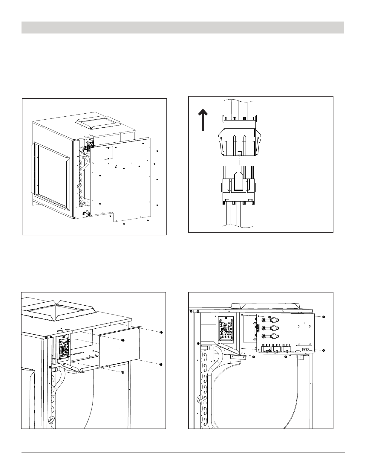
Comfort Pack Installation (Continued)
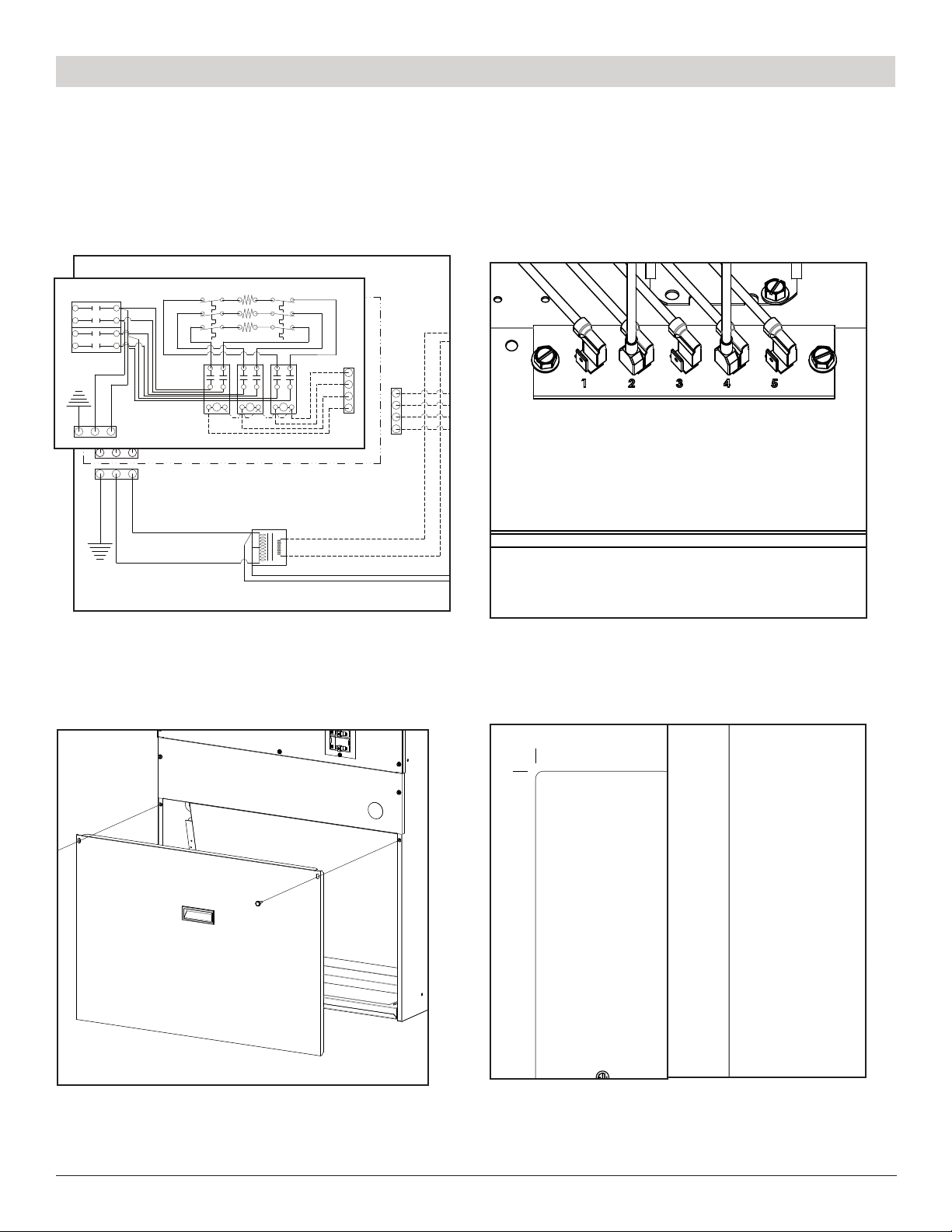
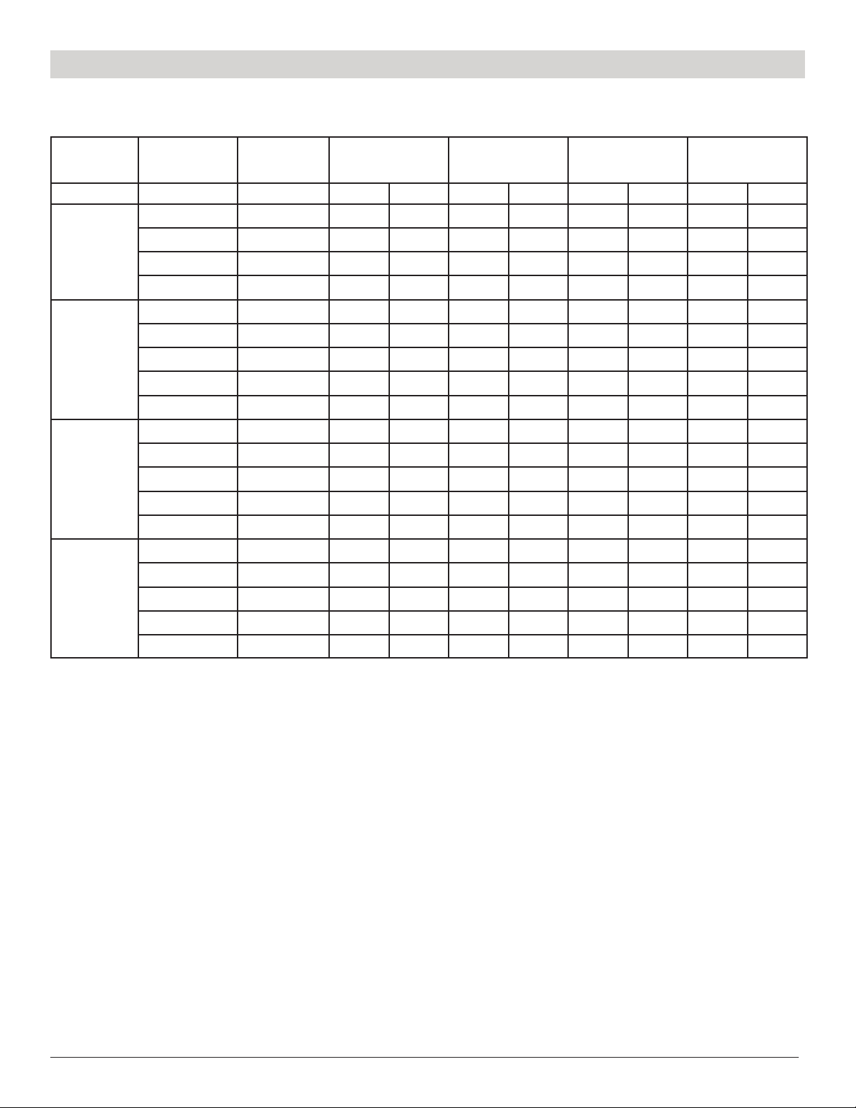
12. On the Unit’s Data Tag, check off the
box next to the heat kit that was installed
in the unit.
Check
Box Heat Kit Model No. Heating kW MCA
(Min. Circuit Ampacity)
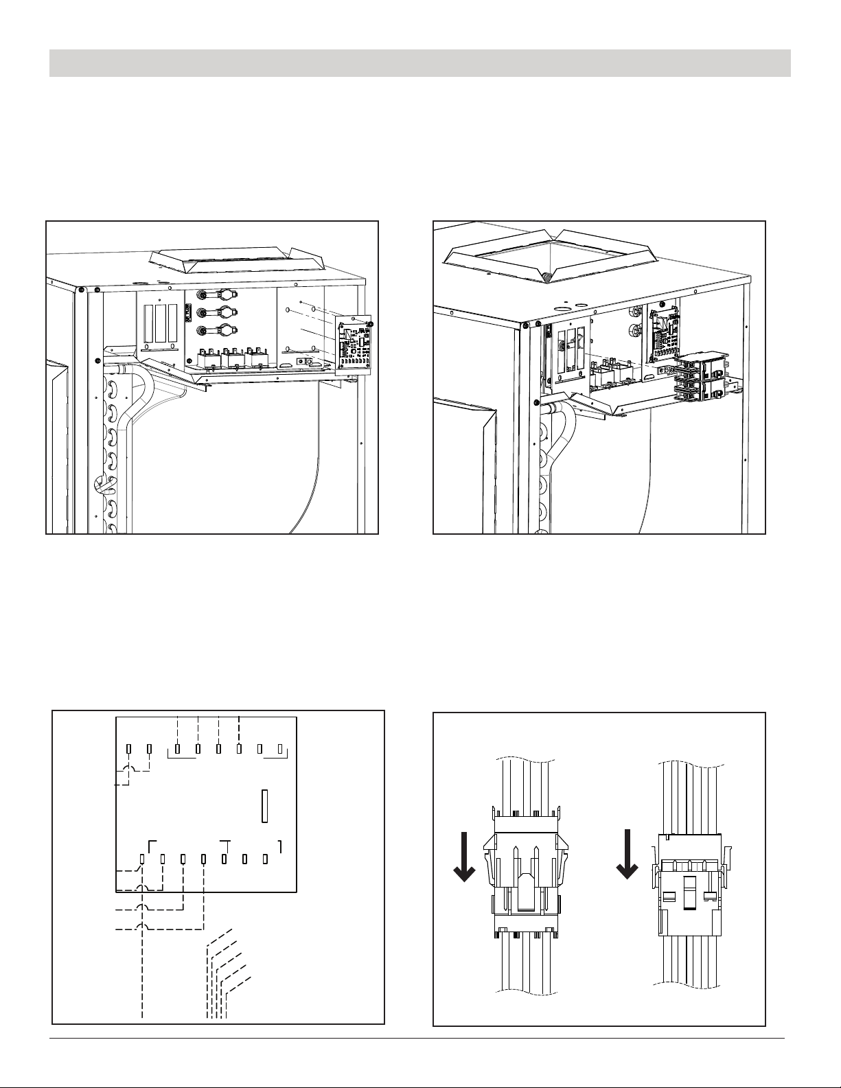
Max Fuse or
Breaker Size
NATIONAL COMFORT PRODUCTS AIR HANDLER
539 DUNKSFERRY RD. BENSALEM, PA 19020
NOTE: Use with outdoor unit R-410A refrigerant only
(REMARQUE : À utiliser avec l'unité extérieure avec le réfrigérant R-410A uniquement)
ELECTRICAL RATING - CARACTÉRISTIQUE ÉLECTRIQUE
For Indoor Installation Only (IPXO) / (Pour installation à l'intérieur seulement)
MAX. EXTERNAL STATIC PRESSURE 0.5'' WC
HEATING DESCRIPTION - DESCRIPTION DE CHAUFFAGE
SERIAL NO. / NUMÉRO DE SÉRIE
MODEL NO. / NUMÉRO DU MODÈLE
Min. Test Pressure
(La Pression D'eprouve Minimale)
Max. Allow. Pressure
(La Pression Maximale Admissible)
BLOWER MOTOR
(Moteur De La Soufflante)
SHORT CIRCUIT CURRENT
(Courant De Court-Circuit)
kA RMS SYMMETRICAL
(kilo ampères RMS SYMÉTRIQUE) HP
0 0 4.8 4.9 15 15
3.2 2.62 22.1 20.6 25 25
4.68 3.83 30.2 27.9 35 30
6.58 5.37 40.5 37.2 45 40
9.35 7.64 55.6
28.6 26.2
50.8 60 60
14.02 11.47 54 49.2 60
30
50
30
230V 208V 230V 208V 230V 208V
None
CPEHK-03-A
FLA
(208V/230V)
VOLTS MIN/MAX VOLTAGE / VOLTAGE MIN/MAXPH HZ
PSIG
KPA KPA
PSIG
(PRESSION STATIQUE EXTERNE MAX. 0.5'' WC)
MINIMUM SPACING TO COMBUSTIBLE SURFACES 0.0"
(ESPACEMENT MINIMUM AUX SURFACES COMBUSTIBLES 0,0")
MAXIMUM OUTLET AIR TEMPERATURE 200 °F
(TEMPÉRATURE MAXIMALE DE L'AIR DE SORTIE 200 °F)
USE COPPER CONDUCTORS ONLY, MOTORS ARE THERMALLY PROTECTED
(UTILISER UNIQUEMENT DES CONDUCTEURS EN CUIVRE, LES MOTEURS SONT
PROTÉGÉS THERMIQUEMENT)
CPEHK-05-A
CPEHK-07-A
CPEHK-10-A
CPEHK-15-A
Note: When Installing an Electric Heat Kit, please refer to the above table for Fuse or
Breaker size selection and put a check mark on its respective check box.
(REMARQUE : Lors de l'installation d'un kit de chauffage électrique, veuillez vous référer au
tableau ci-dessus pour la sélection de la taille du fusible ou du disjoncteur et cochez la case
correspondante.)
53533
CERT. TO: UL-60335-1:2016 Ed.6 & CSA C22.2#60335-1: 2016 Ed.2
UL-60335-2-40:2019 Ed.3 & CSA C22.2#60335-2-40: 2019 Ed.3
14291115
9. Afx the wiring diagram label included in
the accessories kit on the dotted line area
of the cabinet’s wiring diagram.
5/4/2022
DATE
DRAWN BY
BS
WIRING DIAGRAM
NAH4**MFA-*1
JOB NUMBER
MF AIR HANDLER
CAP - DUAL CAPACITOR
CB - CONTROL BOARD
CC - COMPRESSOR CONTACTOR
CFM - CONDENSER FAN MOTOR
COMP - COMPRESSOR
EBM - EVAPORATOR BLOWER MOTOR
PART NUMBER
14291122
HPS - HIGH PRESSURE SWITCH
LPS - LOW PRESSURE SWITCH
XFMER - TRANSFORMER
TB - TERMINAL BOARD
FAX: 215-639-1674
Phone: 800-523-7138
Bensalem, Pa. 19020
539 DUNKSFERRY RD.
R C Y G
LINE VOLTAGE:
LOW VOLTAGE:
CW1A W1B W2 Y COOL HEAT
CONTACTOR COILS FAN OUTPUTS
C R R C Y G W2 W1
TO THERMOSTAT
CB
RED
BLACK
YELLOW
GREEN
EBM
WHITE
RED - HIGH
YELLOW - MED HIGH
BLUE - MED
BLACK - MED LOW
ORANGE - LOW
FAN SPEEDS
208
230
-+
C
XFMER
*TRANSFORMER
FACTORY SET POINT IS
230V, FIELD
ADJUSTMENT REQUIRED
FOR 208V APPLICATION.
DISCONNECT
NON-FUSED
OPTIONAL
FUSED OR
L2L1
G
GREEN
WHITE
BLACK
GREEN
WHITE
BLACK
RED
BLACK
WHITE
0
1
-
+
24V
COIL
4
2
6
8
0
1
-
+
24V
COIL
4
2
6
8
0
1
-
+
24V
COIL
4
2
6
8
HL
HTR1
HTR2
HL
HTR3
HL
WHITE
WHITE
BLACK
BLACK
BLACK
FL
FL
FL
WHITE
30A BR
60A BR
HR2
HR3 HR1
L2
L1
L2
L1
BR - BREAKER
FL - FUSIBLE LINK
HL - HIGH LIMIT
HR - HEAT RELAY
HTR - HEATER
GREEN
WHITE
BLACK
BLACK
WHITE
ORANGE
BLUE
14291124
10. Set the appropriate blower speed tap
(orange wire) on the blower speed control
board. Refer to the Comfort Pack Installation
Manual for airow tables and proper setting.
11. Reinstall the lter access panel.
Check
Box Heat Kit Model No. Heating kW MCA
(Min. Circuit Ampacity)
Max Fuse or
Breaker Size
NATIONAL COMFORT PRODUCTS AIR HANDLER
539 DUNKSFERRY RD. BENSALEM, PA 19020
NOTE: Use with outdoor unit R-410A refrigerant only
(REMARQUE : À utiliser avec l'unité extérieure avec le réfrigérant R-410A uniquement)
ELECTRICAL RATING - CARACTÉRISTIQUE ÉLECTRIQUE
For Indoor Installation Only (IPXO) / (Pour installation à l'intérieur seulement)
MAX. EXTERNAL STATIC PRESSURE 0.5'' WC
HEATING DESCRIPTION - DESCRIPTION DE CHAUFFAGE
SERIAL NO. / NUMÉRO DE SÉRIE
MODEL NO. / NUMÉRO DU MODÈLE
Min. Test Pressure
(La Pression D'eprouve Minimale)
Max. Allow. Pressure
(La Pression Maximale Admissible)
BLOWER MOTOR
(Moteur De La Soufflante)
SHORT CIRCUIT CURRENT
(Courant De Court-Circuit)
kA RMS SYMMETRICAL
(kilo ampères RMS SYMÉTRIQUE) HP
0 0 4.8 4.9 15 15
3.2 2.62 22.1 20.6 25 25
4.68 3.83 30.2 27.9 35 30
6.58 5.37 40.5 37.2 45 40
9.35 7.64 55.6
28.6 26.2
50.8 60 60
14.02 11.47 54 49.2 60
30
50
30
230V 208V 230V 208V 230V 208V
None
CPEHK-03-A
FLA
(208V/230V)
VOLTS MIN/MAX VOLTAGE / VOLTAGE MIN/MAXPH HZ
PSIG
KPA KPA
PSIG
(PRESSION STATIQUE EXTERNE MAX. 0.5'' WC)
MINIMUM SPACING TO COMBUSTIBLE SURFACES 0.0"
(ESPACEMENT MINIMUM AUX SURFACES COMBUSTIBLES 0,0")
MAXIMUM OUTLET AIR TEMPERATURE 200 °F
(TEMPÉRATURE MAXIMALE DE L'AIR DE SORTIE 200 °F)
USE COPPER CONDUCTORS ONLY, MOTORS ARE THERMALLY PROTECTED
(UTILISER UNIQUEMENT DES CONDUCTEURS EN CUIVRE, LES MOTEURS SONT
PROTÉGÉS THERMIQUEMENT)
CPEHK-05-A
CPEHK-07-A
CPEHK-10-A
CPEHK-15-A
Note: When Installing an Electric Heat Kit, please refer to the above table for Fuse or
Breaker size selection and put a check mark on its respective check box.
(REMARQUE : Lors de l'installation d'un kit de chauffage électrique, veuillez vous référer au
tableau ci-dessus pour la sélection de la taille du fusible ou du disjoncteur et cochez la case
correspondante.)
53533
CERT. TO: UL-60335-1:2016 Ed.6 & CSA C22.2#60335-1: 2016 Ed.2
UL-60335-2-40:2019 Ed.3 & CSA C22.2#60335-2-40: 2019 Ed.3
14291115