National Luna Portable Power Pack II User manual

Portable Power Pack II
Dual Battery System & Isolator

Index
11
15
7
12
5
6
8
8
9
13
7
9
10
10
11
2
2
3
4
4
Introduction
Wiring Diagram
Installing Battery
Preparing for Installation
Control Panel
Safety Information
Features
Selecting Voltage Profile
Dedicated Charger Port
External Chargers & Inverters
Changing Start Timer
System Operation
CONNECT Application
USB Ports
Warranty
STATUS Messages
Set a Custom Name
Specifications
Adjusting Alarm & Timer values
APP Dashboards
1

Introduction
ŸDo not attempt to charge a non-rechargeable or battery other than 12V.
ŸDo not attempt to use Lithium batteries with the Power Pack II
ŸKeep cables away from sources of high temperature.
ŸBefore installation, read the instructions carefully.
ŸDo not use for any purpose other than indicated in this manual.
ŸAvoid open flames in the vicinity of the battery.
ŸBefore installation, disconnect any existing batteries.
SAFETY INFORMATION :
ŸThe Portable Power Pack is intended for use with 12V lead-acid batteries only.
ŸDo not alter or modify the Portable Power Pack under any circumstances.
ŸNever attempt to charge a damaged or leaking battery.
ŸDo not expose the Portable Power Pack to liquids. Do not immerse in water.
ŸUnauthorized disassembly, repairs or modifications will void any warranty.
ŸAttempts to use the Portable Power Pack for purposes other than indicated in this
manual will void the warranty.
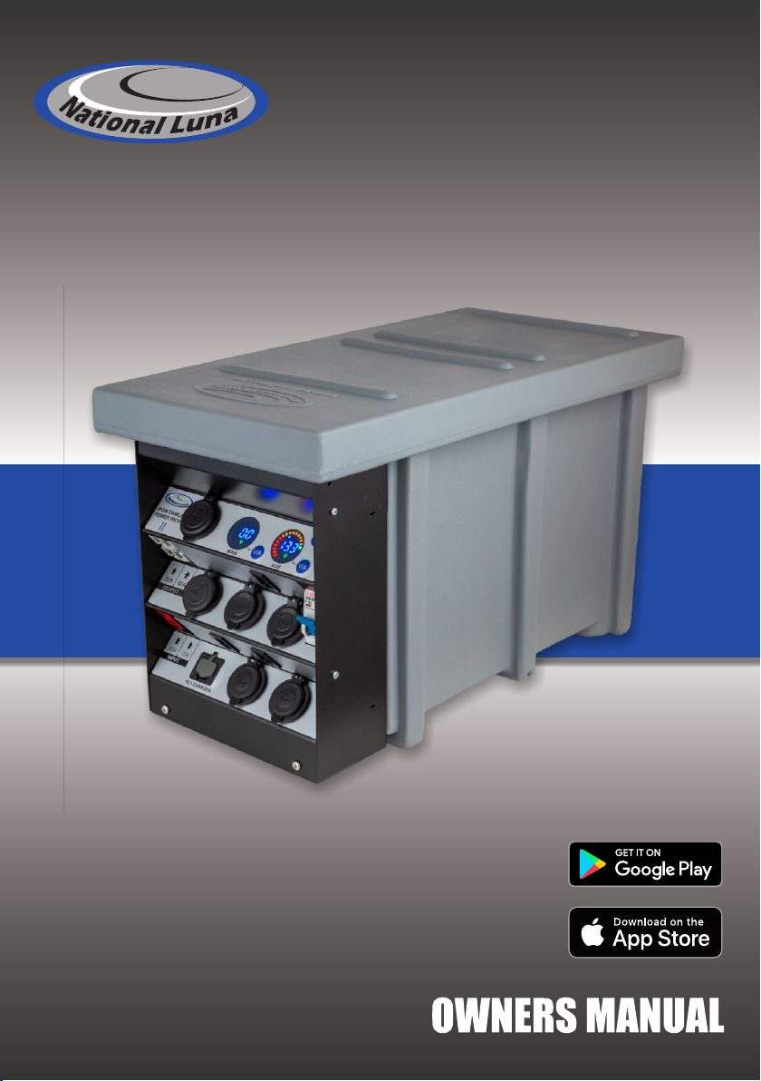
ŸEnsure all connections are secure and cables are installed in a safe manner.
ŸEnsure cables are not clamped or pinched.
ŸEnsure the Portable Power Pack is secured in mobile applications.
ŸUse the correct cabling size and fuses in accordance with the installation instructions.
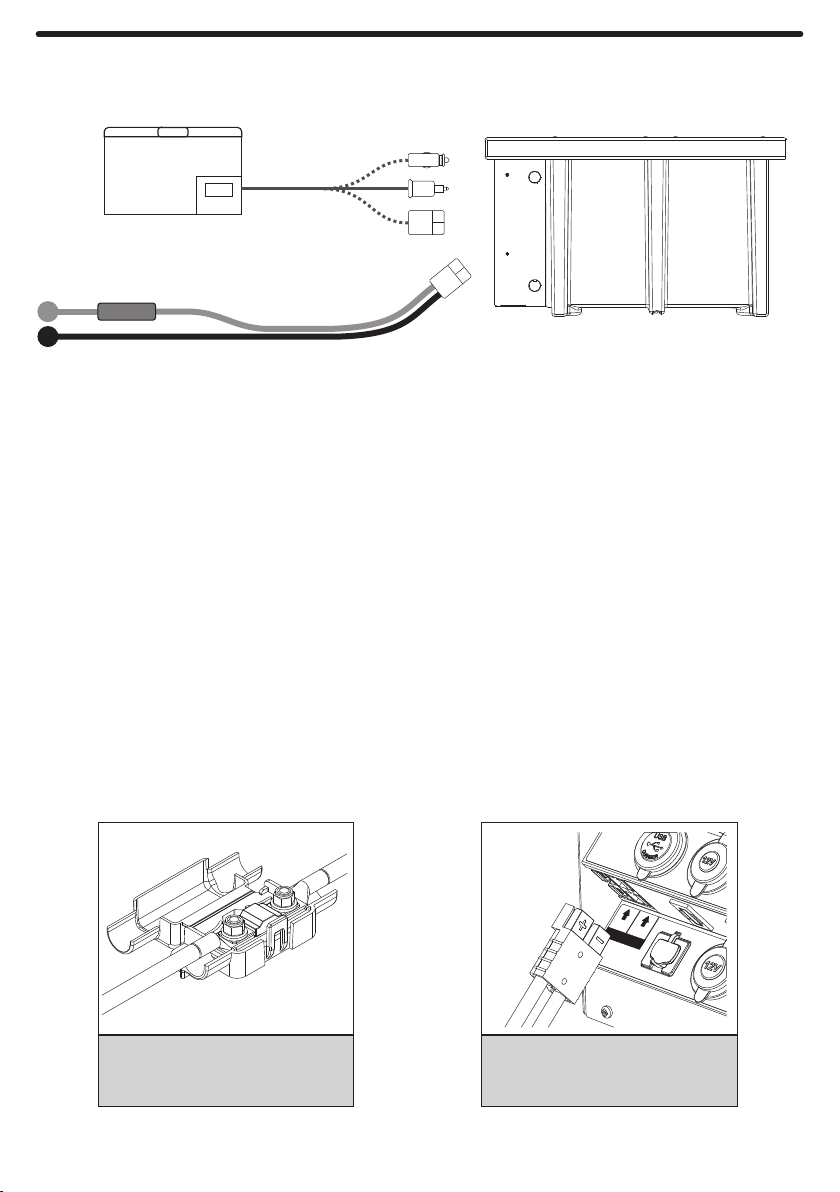
The Portable Power Pack II is a dual-battery system and isolator for use in automotive applications.
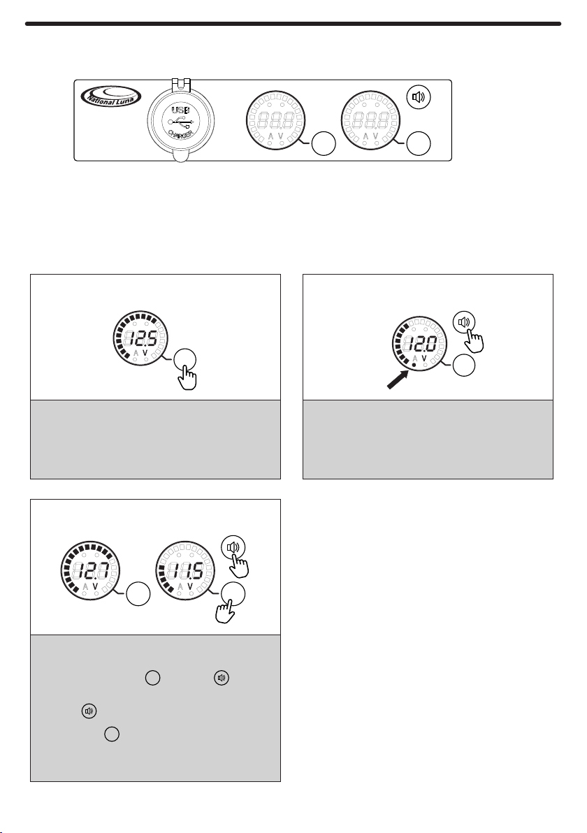
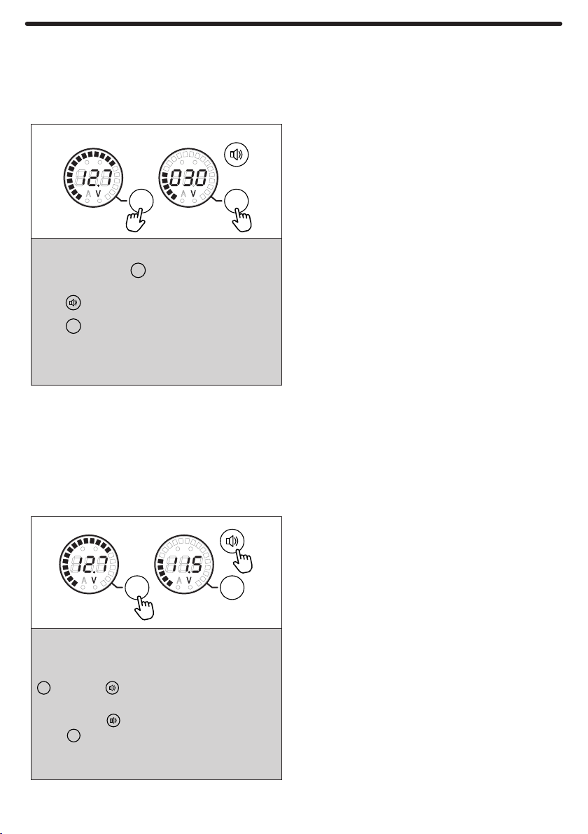
The Power Pack II features a dual-display that can show the respective voltages of the main battery and
auxiliary battery. The respective displays can be switched to show charge current and load current.
It allows an auxiliary battery to charge when the vehicle is running and isolates it from the main battery
when the vehicle is turned off. This prevents the main battery being drained by accessories such as
fridges, lights, pumps, fans, etc.
Battery status, system status and preferences can be viewed and configured on a Bluetooth-connected
smart device using the new CONNECT application.
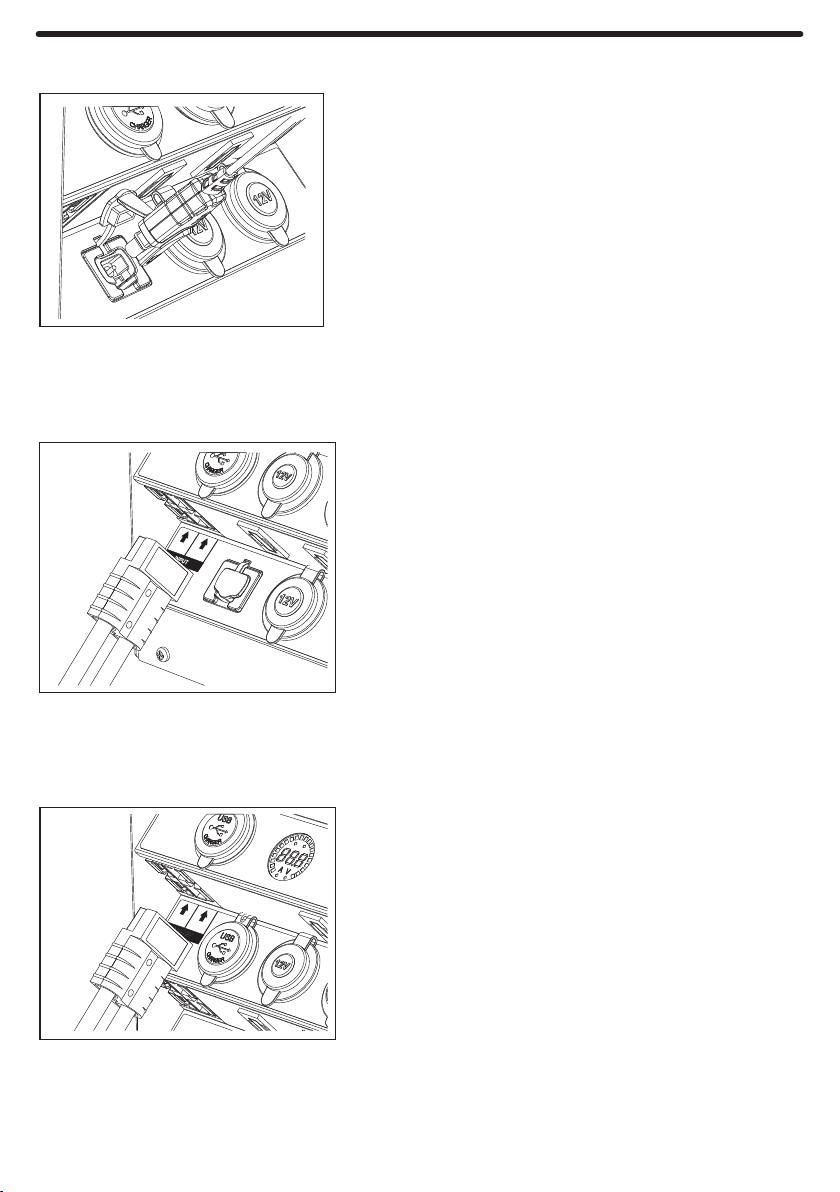
The Power Pack offers a variety of power outputs including standard automotive sockets (cigar type),
Hella type, USB charge ports and heavy-duty 50A couplers.
Supported battery types :
Lithium-based batteries are not supported
including high-cycle / deep-cycle variants of these.
Ÿ12V Lead-acid (Calcium, Flooded, AGM, Gel, VRLA)
Max battery size :
Ÿ350mm x 180mm x 270mm (L x W x H)
2
Battery charge performance will be affected by the alternator voltage.
The Portable Power Pack II relies on the vehicle alternator to provide charge.
It is intended for use in vehicles with alternator voltage above 13.5V.
NOTE :

Features
POWER PACK
PORTABLE
II
MAIN AUX
V/A V/A
50A 50A
OUTPUT
NL5 CHARGER
50A 15A
INPUT
Control Panel
Output sockets
Sliding Lid
Serial number
Battery Compartment
MAIN battery gauge
AUX battery gauge
USB Charge ports
Main Switch
50A Heavy-duty
IN/OUT connectors
Secondary charge input
MAIN BATT input
External Charger input
Hella-type DC sockets
12V DC sockets
Output fuses
Output fuses
3

Wiring diagram - Typical Installation
To vehicle
MAIN battery
Loads (eg fridge / lights)
Fuse
INPUT
100A
+
-
The Portable Power Pack is a complete dual-battery system, it does not require any isolator, solenoid or
other battery system. If there any pre-existing dual-battery systems or isolators, they should be removed
or bypassed for the Power Pack to function properly.
Locate the Portable Power Pack such that the input cables are not restricted or under strain. The Power
Pack should also be secured to prevent movement in a mobile application.
2
Use 16mm cables for the input from the vehicle main battery and install a 100A in-line fuse close to the
main battery on the positive cable (Fig 1).
Make sure all connections are secure and terminated correctly with appropriate tools.
All cables should be protected from high temperature and potential physical damage.
The input cables must be terminated with a RED 50A coupler matching the input on the Portable Power
Pack marked "INPUT" (Fig 2).
Connect the supply from the main
battery (alternator) to the RED input
on the Portable Power Pack.
Ensure terminals are crimped securely.
Install the fuse on the positive cable
close to the main battery.
Fig 1 Fig 2
Preparing for Installation
50A 15A
INPUT
NL5 CHARGER
4

Installing Battery
To hold a battery securely in the Power Pack, install the U-bolt and hold-down bracket.
It is best to lay the Power Pack on its side or end to do this.
1
2
3
Remove the Power Pack sliding lid
and insert the auxiliary battery into
the battery compartment.
Insert the U-bolt through the holes
drilled into the bottom of the
Power Pack.
Return the Power Pack to the
upright position.
Take care not to over-tighten the
screws.
Attach the hold-down bracket,
washers and wing-nuts.
Connect the positive (RED) and
negative (BLACK) cables to the
respective battery terminals.
Make sure the connections are
clean and secure.
5

Control Panel
POWER PACK
PORTABLE
II
MAIN AUX
V/A V/A
The Portable Power Pack control panel comprises of two displays marked as MAIN and AUX.
The MAIN display can show the input voltage or charge current.
The AUX display can show the auxiliary battery voltage or discharge current.
The low-battery alarm voltage and start timer can be adjusted from the control panel.
MAIN
V/A
MAIN AUX
V/A V/A
AUX
V/A
The low-battery warning voltage can be adjusted to
suit the application and battery being used.
Press and hold the AUX button and together.
The current value will be shown.
Press the button to increase the value.
Press the AUX button to decrease the value.
Release all buttons when done. The new value will be
saved and the display will return to normal.
V/A
V/A
Each display can be toggled to show voltage or
current.
Press and hold the V/A button for the respective
display to toggle the display mode. The "V" or "A"
symbols will indicate the selected mode.
The alarm on/off indicator will show if the alarm is
enabled or disabled.
The low-voltage audible alarm can be muted or
un-muted by pressing and holding the alarm button.
Changing display mode
Changing low-battery level
Toggle alarm on / off
ŸThe low-voltage alarm is used to warn of
excessive battery discharge and potential
battery damage. Regular deep-discharge
will reduce battery cycle life.
ŸA voltage of 11.9V is typical of 60%
depth-of-discharge and is recommended
for high-cycle batteries.
ŸA voltage of 11.5V is typical of 80%
depth-of-discharge and is the deepest
recommended discharge for deep-cycle
batteries.
ŸDischarging below 11.4V is not
recommended for most batteries.
6

MAIN AUX
V/A V/A
The current value will be shown.
Press to decrease the value.
Press to increase the value.
The start timer can be adjusted to suit the application.
Press and hold both buttons together.
Release all buttons when done. The new value will be
saved and the display will return to normal.
V/A
V/A
To select a voltage profile, press and hold the MAIN
Press the AUX button to increase the value.
Press to decrease the value.
button and button together.
Release all buttons when done. The new value will be
saved and the display will return to normal.
A voltage profile can be chosen to suit a particular
vehicle or application.
V/A
V/A
Changing Start Timer
The Start Timer defines the delay after starting the vehicle when the Power Pack connects the
auxiliary battery and allows charge to flow to it. This delay can be adjusted for various vehicles and
applications.
Changing Voltage Profile
The Power Pack detects when the vehicle has started and when it has stopped by measuring the
voltage on the MAIN input. The Voltage Profile is used to adjust this threshold to ensure reliable
detection in a variety of different vehicles and applications.
ŸVehicles with a lower alternator voltage
can use a lower voltage profile. This may
be necessary for vehicles with "smart"
alternators.
ŸThe voltage profile selected will also
affect the turn-off voltage (when the
Power Pack isolates the Auxiliary
battery).
ŸVehicles with a higher alternator voltage
can use a higher voltage profile.
ŸA value of 13.2V-13.3V is recommended
for most applications.
ŸA longer delay is useful for vehicles with
lower-power alternators. It allows for the
Main battery to receive charge for longer
before charge is shared to the Auxiliary
battery. This can prevent alternator over-
load.
ŸThe start timer can be set between
ŸFor vehicles with more powerful
alternators, a shorter delay can be
chosen. This connects the Auxiliary
battery sooner but can put more load on
the alternator initially.
30 seconds and 8 minutes in increments
of 30 seconds.
MAIN AUX
V/A V/A
7

Dedicated Charger Port
Connecting External Chargers
SOLAR CHARGE - In order to supply the Power Pack
with Solar power, an external solar regulator is required.
Connect the output from the regulator to the secondary
input.
If the charge source has a current greater than 15A,
connect it directly to the battery terminals.
The Portable Power Pack has a secondary charge input
that is designed for use with larger AC battery chargers
and solar regulators up to 15A.
In order to connect other brands of chargers to this input,
a quick-connector cable is available separately.
Make sure the main breaker switch is in the ON position
during charge.
The Portable Power Pack has a charge port specifically
for use with National Luna Intelligent Battery Chargers.
Insert the charger quick-connector into the charge port
labeled "NL5 CHARGER" until it clicks securely.
This port can support up to 10A charge current.
NL5 CHARGER
When using chargers or inverters connected to the
OUTPUT plugs, the main switch must be ON.
High-current loads such as AC Inverters can be
connected to the OUTPUT plugs for powers up to 600W.
Larger-power loads exceeding 600W (50A) should be
connected directly to the battery terminals instead.
Connecting inverters and high-power loads.
50A 15A
50A 50A
8

System operation
In order to charge or supply power to accessories connected to any
of the plugs & sockets, the main switch must be in the ON position.
If the Portable Power Pack is not in use then it is best to turn this
switch OFF. This will completely isolate the auxiliary battery.
Main Isolator Switch
The Portable Power Pack will detect when the vehicle is started and begin the Start Timer when the voltage
present on the MAIN input exceeds the value set by the Voltage Profile.
Following the Start Timer (period set by user), the Power Pack connects the auxiliary battery and allows it
to receive charge. Charge current can be viewed on the MAIN display by setting the mode to Current (A).
The auxiliary battery remains isolated at this stage.
During this time, input voltage and current is monitored. If a fault condition is detected, the auxiliary battery
is disconnected.
If the input voltage remains below the stop voltage, the Power Pack enters a standby state.
If the input voltage falls below the Stop voltage (derived from Voltage Profile), the auxiliary battery is
isolated and the Power Pack enters a paused state.
9V : 2A
Each port is able to deliver up to 18W of power compatible
with QuickCharge 3.
5V : 3A
NOTE : The charge rate is device-dependent. Not all USB
devices will utilize QuickCharge.
The Portable Power Pack offers multiple USB charge ports
ideal for charging smart devices (mobile phone, tablet, GPS,
cameras, power bank, etc)
12V : 1.5A
USB charge ports
9
QC 3.0
MAIN
Table of contents
Other National Luna Batteries Pack manuals


