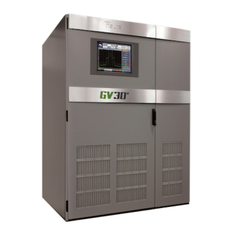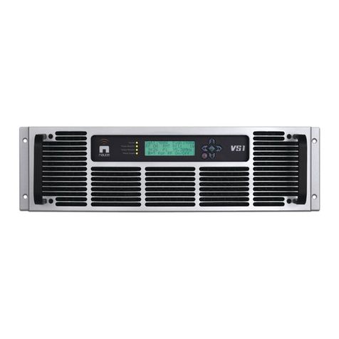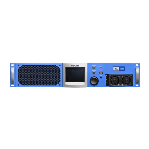
NX200 Main-Standby Transmitter System Installation and Operation Manual Oct.28.14
Factory Support
TECHNICAL ASSISTANCE
The Nautel field service department provides telephone technical assistance on a 24 hour, seven days a week basis.
Requests by other media (facsimile or e-mail) will be responded to the next working day if received after Nautel's normal
working hours. Contact the appropriate field service centre from the following:
U.S.A. customers use: Nautel Incorporated Telephone 207-947-8200 (24 hours)
201 Target Industrial Circle Facsimile 207-947-3693
Bangor, Maine 04401
All other customers use: Nautel Limited Telephone 902-823-3900 (24 hours)
10089 Peggy’s Cove Road, Facsimile 902-823-3183
Hackett’s Cove, NS, Canada E-Mail support@nautel.com
B3Z 3J4 Web www.nautel.com
MODULE EXCHANGE SERVICE
In order to provide Nautel customers with a fast and efficient service in the event of a problem, Nautel operates a factory
rebuilt, module exchange service which takes full advantage of the high degree of module redundancy in Nautel
equipment. This module exchange service is operated from Nautel’s factory in Bangor, Maine and Hackett’s Cove,
Nova Scotia. These two locations allow us to provide a quick turn around service to keep our customers on the air.
During the transmitter’s warranty period, up to thirteen months from shipment, repair and exchange of modules is at no
charge to the customer. When the warranty has expired, a charge of 80% of the list price for all exchanged modules is
made. If the faulty module is returned to Nautel within 30 days, a credit is issued reducing this charge by one half to
40% of the list price. U.S.A. customers are required to contact our Bangor, Maine facility. Canadian and overseas
customers should contact our Nova Scotia, Canada facility.
EQUIPMENT BEING RETURNED TO NAUTEL
For all equipment being returned to Nautel and all requests for repairs or replacements:
Obtain an RMA number from Nautel (you must have an RMA number to return equipment)
Mark the item as 'field return'
Mark the item with the RMA number assigned by Nautel
Address the item to the appropriate Nautel facility
Complete and accurate information regarding the equipment being returned will ensure prompt attention and will
expedite the dispatch of replacements. Refer to the nameplate on the transmitter and/or the appropriate
module/assembly to obtain name, type, part and serial number information. Refer to the parts list of this manual or the
appropriate service instruction manual for additional ordering information.
The following information should accompany each request:
* Model of Equipment
* Serial number of Equipment
* Name of Part/Assembly
Serial number of Part/Assembly
* Complete reference designation of Part/Assembly
* Nautel's part number of Part/Assembly
* OEM's part number of Part/Assembly
Number of hours in Use
Nature of defect
* Return shipping address
* Denotes minimum information required to order spare/replacement parts

