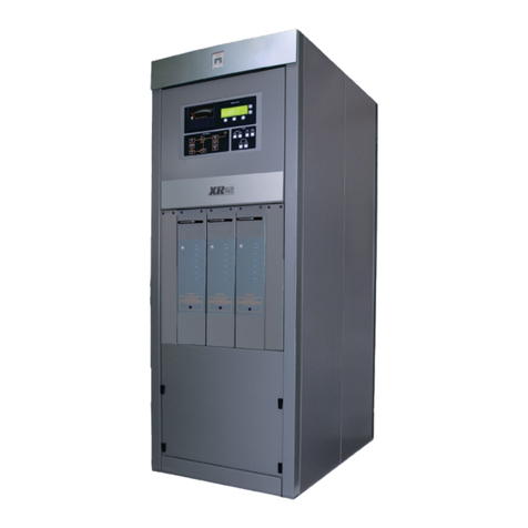
Nautel ND500II-113-x21 User manual

MAIN/STANDBY 125 WATT RADIOBEACON TRANSMITTERS WITH CRCU and NDDS/T
(USER SUPPLIED ENCLOSURE/CABINET)
IS02007 (Page 1)
15 February 2002
INTRODUCTION
1. When two ND500II 125 watt radiobeacon
transmitters, an NAX51A computer remote control
unit (CRCU) and an NDDS/T Dual Direct Digital
Synthesizer (DDS) are installed in a main/standby
installation, some mechanical information in the
transmitter's instruction manual must be changed and
the cabinet's electrical information is required. This
document identifies the mechanical differences. It
also provides an electrical parts list and point-to-
point wiring information for the cabinet. It is
recommended that, where replacement pages are not
provided, affected areas of the transmitter instruction
manual be highlighted using a suitable marker, or
changed using pen and ink, to ensure users of the
manual are aware of the differences.
1.1 MAIN TRANSMITTER: The
transmitter identified as ND500II-113-x21 on its
nameplate must be used as the main transmitter.
This transmitter has an NAF107/02 harmonic filter
assembly, which contains a main/standby
changeover relay and an additional type 'N' coaxial
connector (J3). The changeover relay ensures only
one transmitter is turned on and that the RF output of
the active transmitter is applied to the antenna
system's antenna tuning unit (ATU). The main
transmitter is enabled as long as its RF output is
satisfactory. See ND500II instruction manual for
details on the NAF107/02 harmonic filter assembly.
1.2 STANDBY TRANSMITTER: The
transmitter identified as ND500II-013-x21 on its
nameplate must be used as the standby transmitter.
MECHANICAL DIFFERENCES
2. There are no drawer slides on the
transmitters, as depicted in figure MD-17. The
method of installation will determine how access is
gained for servicing. References to extension and
swivelling of the transmitter in the instruction
manual should be ignored. If it is not possible to
access a specific area of the transmitter when it is
installed, the transmitter must be moved to a suitable
work surface.
OPERATION
3. Refer to the ND500II technical instruction
manual for transmitter operation, including the
function of the remote inputs and outputs which are
not related to main/standby operation. Refer to the
NAX51 manual for computer remote control unit
(CRCU) operation. Refer to the NAX198 manual
for NDDS/T operation.
NOTE
The 'A' transmitter contains the main/standby RF
routing relay. This relay is connected as a fail-safe
device which is energized when the 'A' transmitter is
operational (on-air) and de-energized when the 'A'
transmitter is non-operational (turned off/
shutdown). When the relay is energized, the RF
output of the 'A' transmitter is routed to the antenna.
When the relay is de-energized, the RF output of the
'B' transmitter will be routed to the antenna.
3.1 SYSTEM OPERATING STATUS: The
system's xmtr on status and shutdown alarm outputs
provide an indication of the system operating status.
3.1.1 If the 'A' or 'B' transmitter is turned on and
producing a satisfactory RF output, the following
will be true, regardless of the system's main/standby
status:
(a) The system's xmtr on status output at 3TB2-10
(XMTR ON) of the remote control interface
assembly will be a ground potential.
(b) The system's shutdown alarm output at 3TB1-3
(SHT DN ALM) of the remote control interface
assembly will be a positive DC voltage.
3.1.2 If neither transmitter is enabled (not
turned on or shut down because of malfunctions),
indicating the system is non-operational and is not
producing an RF output, the following will be true:
(a) The system's xmtr on status output at 3TB2-10
(XMTR ON) of the remote control interface
assembly will be a positive DC voltage.
(b) The system's shutdown alarm output at 3TB1-3
(SHT DN ALM) of the remote control interface
assembly will be a ground potential.
MAIN/STANDBY 125 WATT RADIOBEACON TRANSMITTERS WITH CRCU and NDDS/T
(USER SUPPLIED ENCLOSURE/CABINET)
IS02007 (Page 2)
15 February 2002
3.2 MAIN/STANDBY OPERATION:
Main/standby operation requires the 'A' and 'B'
transmitters to be in-circuit and functional. The
main/standby control circuitry on the remote control
interface assembly will dictate which transmitter is
selected as the main transmitter and which one is
operational (on-air). The operational (on-air)
transmitter will provide 24VDC source voltage to the
NDDS/T which will then provide a RF signal at the
transmitter’s operating frequency to J3 (Ext RF
Drive) of the operational transmitter.
3.2.1 Selection of Main Transmitter: The
setting of the remote control interface assembly's
SELECT MAIN TX switch (3S1) determines which
transmitter is designated and selected as the main
transmitter, when the 'A' and 'B' transmitters are
operational.
3.2.2 Main Transmitter Operational: When
the transmitter selected by the SELECT MAIN TX
switch is turned on and producing a satisfactory RF
output, the following will occur:
(a) The source voltage for NDDS/T’s 24VDC
inputs will be provided by the selected main
transmitter. The NDDS/T will provide a RF
signal at the transmitter’s operating frequency
to J3 (Ext RF Drive) of the selected main
transmitter.
(b) The 24VDC and 15VDC voltages required by
the remote control interface assembly will be
provided by the selected main transmitter.
(c) The standby transmitter will be turned off
(inhibited). 15VDC will be applied to TB1-6
of the standby transmitter as its stby on/off
input from the remote control interface
assembly.
(d) The RF output from the selected main
transmitter will be routed to the antenna by the
main/standby relay in transmitter A's harmonic
filter.
(e) The antenna tuning unit operating voltage and
controls (TB2-3/4/5/8) will be provided by the
selected main transmitter.
(f) The system's remote audio output at 3TB1-9
(RMT AUD) of the remote control interface
assembly will be provided by the selected main
transmitter.
(g) The system's changeover alarm output at
3TB1-10 (CHG OV ALM) of the remote control
interface assembly will be a positive DC
voltage, indicating the selected main
transmitter is operational and a changeover to
the standby transmitter has not occurred.
3.2.3 Standby Transmitter Operational:
When the transmitter selected by the SELECT MAIN
TX switch shuts down because of a malfunction or is
intentionally turned off, the main/standby circuitry
will automatically enable the standby transmitter (in-
circuit transmitter not selected as the main
transmitter) and route its RF output to the antenna.
When the standby transmitter is on-air, the following
will occur:
(a) The 24VDC and 15VDC voltages required by
the remote control interface assembly will be
provided by the standby transmitter.
(b) The main transmitter will be off (inhibited).
15VDC will be applied to TB1-6 of the main
transmitter as its stby on/off input from the
remote control interface assembly.
(c) The RF output from the selected standby
transmitter will be routed to the antenna by the
main/standby relay in transmitter A's harmonic
filter.
(d) The source voltage for NDDS/T’s 24VDC
inputs will be provided by the selected standby
transmitter. The NDDS/T will provide a RF
signal at the transmitter’s operating frequency
to J3 (Ext RF Drive) of the selected standby
transmitter.
(e) The antenna tuning unit operating voltage and
controls (TB2-3/4/5/8) will be provided by the
standby transmitter.
(f) The remote audio output at 3TB1-9 (RMT AUD)
of the remote control interface assembly will
be provided by the standby transmitter.

MAIN/STANDBY 125 WATT RADIOBEACON TRANSMITTERS WITH CRCU and NDDS/T
(USER SUPPLIED ENCLOSURE/CABINET)
IS02007 (Page 3)
15 February 2002
(g) The system's changeover alarm output at
3TB1-10 (CHG OV ALM) of the remote control
interface assembly will be a ground potential,
indicating a changeover to the standby
transmitter has occurred.
3.3 REMOTE (CRCU) CONTROL/
MONITORING: A computer remote control unit
(CRCU) provides the control/monitoring interface
between the main/standby transmitter system and the
host (master) system.
3.3.1 Remote On/Off Control: A transmitter
off command is applied to TB2-6 (ON/OFF) of each
transmitter from the computer remote control unit
(CRCU). If a transmitter's CONTROL switch has
been set to REMOTE, this command will turn off the
(both) transmitter(s) when it is an open circuit and it
will turn on the (both) transmitter(s) when it is a
current-sink-to-ground. If a transmitter's CONTROL
switch has been set to LOCAL,this command will
have no influence.
NOTE
The CONTROL switch, on the front panel of each
transmitter must be in the REMOTE position in order
for the CRCU to have on/off control.
3.3.2 Standby Transmitter Check: When the
standby transmitter is to be turned on from a remote
location to check its operational availability and the
main transmitter is to be restored as the on-air
transmitter on completion of the check, the following
must occur:
(a) The remote control interface assembly's RMT
XFR switch must be set to ENABLE.
(b) A ground potential transfer command must be
applied to 3TB2-6 (XFR CMD) of the remote
control interface assembly from the computer
remote control unit (CRCU) for the duration of
the check.
(c) While a ground potential is being applied to
3TB2-6, the standby transmitter will be
enabled as detailed in paragraph 3.2.3.
(d) When the ground potential is removed from
3TB2-6 or the REMOTE TRANSFER switch is
set to DISABLE,the standby transmitter will be
turned off and the selected main transmitter
will be restored as the operational transmitter
as detailed in paragraph 3.2.2.
THEORY OF OPERATION
4The remote control interface circuits,
which provide the main/standby transmitter control
and main/standby related remote monitoring outputs
are described in the following. Refer to figure SD-1
for the system electrical schematic and then to figure
SD-2 for the remote control interface assembly's
electrical schematic.
NOTE
Remote control/monitoring of the main/standby
transmitter system is accomplished via the computer
remote control unit (unit 4) in conjunction with the
remote control interface assembly (unit 3). The
theory contained in this document pertains to the
remote interfacing provided by the remote control
interface assembly. Refer to the CRCU instruction
manual for its theory of operation.
4.1 ND500II TRANSMITTERS: Refer to
the ND500II - 125 radio beacon technical instruction
manual for a detailed theory of operation for the
transmitters. The theory for both transmitters is
identical with one major exception. The 'A'
transmitter's harmonic filter contains a main/standby
relay which routes the output of the on-air transmitter
to the antenna.
4.1.1 Transmitter Standby Control: The
stby on/off control input at TB1-6 of each transmitter
is provided by the main/standby circuitry in the
remote control interface assembly (unit 3).
4.1.1.1 When a transmitter is to be inhibited (its
RF output is turned off) because it is being held in
reserve as the standby transmitter, its stby on/off
input will be +15vdc. The following will be true:
(a) The +24VDC output at A7TB6-6 of the
transmitter will be 0.0VDC.
(b) The +15VDC output at TB2-1 of the
transmitter will be 0.0VDC.

MAIN/STANDBY 125 WATT RADIOBEACON TRANSMITTERS WITH CRCU and NDDS/T
(USER SUPPLIED ENCLOSURE/CABINET)
IS02007 (Page 4)
15 February 2002
(c) The B+VDC output at TB1-10 of the
transmitter will be the B+ voltage.
(d) The remote shutdown alarm output at TB2-7 of
the transmitter will be an open collector.
(e) The +15VDC output, for the ATU, at TB2-8 of
the transmitter will be 0.0VDC.
(f) The ATU controls at TB2-3/4/5 of the
transmitter will have no influence.
4.1.1.2 When a transmitter is to be enabled, as the
main or standby transmitter, its stby on/off input will
be 0.0VDC. The transmitter will be turned on and
the following will be true:
(a) The +24VDC output at A7TB6-6 of the
transmitter will be +24VDC.
(b) The +15VDC output at TB2-1 of the
transmitter will be +15VDC.
(c) The B+VDC output at TB1-10 of the
transmitter will still be the B+VDC.
(d) The remote shutdown alarm output at TB2-7 of
the transmitter will be a current-sink-to-ground.
(e) The +15VDC output, for the ATU, at TB2-8 of
the transmitter will be +15VDC.
(f) The ATU controls at TB2-3, TB2-4 and TB2-5
of the transmitter will be the remote tuning
control source for the ATU.
4.1.1.3 If an operational transmitter shuts down,
its main/standby related outputs will immediately
assume the states identified in steps (a) through (f) of
paragraph 4.1.1.1.
4.2 SYSTEM ON/OFF STATUS: The
status of the shutdown alarm output at 3TB1-3 or the
transmitter on/off status output at 3TB2-10 is
determined by the status of relay 3K1.
4.2.1 If any transmitter is operational,
regardless of the main/standby status, +24VDC will
be applied to 3TB1-1 or 3TB1-2. Relay 3K1 will be
held energized.
(a) The xmtr on output at 3TB2-10 will be a
ground potential.
(b) The sht dn alm output at 3TB1-3 will be a
positive DC voltage.
4.2.2 If both in-circuit transmitters are shut
down and the system is non-operational, regardless
of the reason, +24VDC will not be applied to 3TB1-
1/3TB1-2. Relay 3K1 will be de-energized.
(a) The xmtr on output at 3TB2-10 will be a
positive DC voltage.
(b) The sht dn alm output at 3TB1-3 will be a
ground potential.
4.3 B+VDC STATUS: If a transmitter is
operational, regardless of the main/standby status; its
B+VDC will be applied thru 3TB2-11 or 3TB2-5,
whichever is applicable, to 3TB2-12.
4.4 MAIN/STANDBY
CONFIGURATION: When the 'A' and 'B'
transmitters are both in-circuit and they are
operationally available, they will be operating as a
main/standby transmitter system. One of the
transmitters will be inhibited by the application of a
+15VDC stby on/off input to its TB1-6 and it will be
held in reserve as the standby transmitter.
4.4.1 Main Transmitter Selection: The
setting of the SELECT MAIN TX switch (3S1)
determines which transmitter, 'A' or 'B', is selected as
the main transmitter. The SELECT MAIN TX switch
performs three functions:
(a) It ensures the transmitter not selected as the
main transmitter is held in reserve as the
standby transmitter, as long as the selected
main transmitter is operational. It does this by
routing the +15VDC applied to 3TB2-7 or
3TB2-8, from the main transmitter, through
3TB2-1 or 3TB2-2 to TB1-6 of the standby
transmitter as its stby on/off input.
(b) It ensures the state of main tx status relay K5
is controlled by the shutdown alarm (sht dn
alm) output of the selected main transmitter.
Relay K5 will be energized when the selected
main transmitter is operational and applying a
ground as the changeover alarm. It will be de-

MAIN/STANDBY 125 WATT RADIOBEACON TRANSMITTERS WITH CRCU and NDDS/T
(USER SUPPLIED ENCLOSURE/CABINET)
IS02007 (Page 5)
15 February 2002
energized when the main transmitter is shut
down and applying a positive DC voltag as the
changeover alarm.
(c) It determines the energized/de-energized state
of 'A'/'B' relay K3. K3 will be energized when
transmitter 'A' is selected as the main
transmitter and it will be de-energized when
transmitter 'B' is selected as the main
transmitter.
4.4.2 Changeover Alarm Status: The status
of the changeover alarm output at 3TB1-10 (CHG OV
ALM) is determined by the energized/ de-energized
state of main tx status relay K5, which in turn is
determined by the on/off status of the selected main
transmitter [see step (b) of paragraph 4.4.1]. It will
be a positive DC voltage when relay K5 is energized
(main transmitter operational) or a ground potential
when relay K5 is de-energized (main transmitter shut
down).
4.5 REMOTE AUDIO SOURCE: The
source of the audio which is provided for remote
monitoring is determined by the energized/de-
energized states of main tx status relay K5 [see step
(b) of paragraph 4.4.1] and 'A'/'B' relay K3 [see step
(c) of paragraph 4.4.1].
4.5.1 The remote audio being applied to 3TB1-
6 from the 'A' transmitter is routed to 3TB1-9 (RMT
AUD) as the system remote audio output when:
(a) Relays K3 and K5 are both energized
(transmitter 'A' is selected as the main
transmitter and it is operational).
(b) Relays K3 and K5 are both de-energized
(transmitter 'B' is selected as the main
transmitter but it has failed and a changeover to
the standby transmitter has occurred and the 'A'
transmitter is operational.
4.5.2 The remote audio being applied to 3TB1-
8 from the 'B' transmitter is routed to 3TB1-9 (RMT
AUD) as the system remote audio output when:
(a) Relay K3 is energized and relay K5 is de-
energized (transmitter 'B' is selected as the
main transmitter and it is operational).
(b) Relay K3 is de-energized and relay K5 is
energized (transmitter 'A' is selected as the
main transmitter but it has failed, a changeover
to the standby transmitter has occurred and the
'B' transmitter is operational.
INSTALLATION INFORMATION
5. Complete or verify the following
requirements are completed during installation of the
main/standby transmitter system.
5.1 UNPACKING: The transmitters and
CRCU/remote control interface and NDDS/T Dual
Direct Digital Synthesizer are packed in individual
crates for shipping. Remove them from their crates
and perform a visual inspection in preparation for
system assembly.
5.1.1 It is recommended the main and standby
transmitters, associated remote interfacing
assemblies (including CRCU) and NDDS/T Dual
Direct Digital Synthesizer be installed in an
enclosure that will permit access to their assemblies
during maintenance and trouble shooting procedures.
Install the transmitters as described in the ND500II
instruction manual using figures 1 and SD-1 of this
document as a guide to complete the internal
electrical interconnection between transmitters (units
1 and 2), remote control interface assembly (unit 3),
computer remote control unit (unit 4) and NDDS/T
Digital Direct Digital Synthesizer (unit 5)
5.2 POSITIVE IDENTIFICATION: If the
identification tag has been removed from the front
handle of a transmitter, the following will provide a
positive identification.
5.2.1 The transmitter that must be installed as
the ‘A’ (xmtr 1) transmitter contains a main/ standby
relay and two type 'N' coaxial connectors in/on its
harmonic filter. The transmitter which has a '1' as the
first digit of the first group of three numbers
(ND500-1xx-xxx) of its identifier number must be
installed as the 'A' transmitter. This identifier is
stamped on the variation nameplate, which is located
on the transmitter's upper, front, right-hand side.

MAIN/STANDBY 125 WATT RADIOBEACON TRANSMITTERS WITH CRCU and NDDS/T
(USER SUPPLIED ENCLOSURE/CABINET)
IS02007 (Page 6)
15 February 2002
5.2.2 The transmitter which must be installed as
the 'B' (xmtr 2) transmitter has a '0' as the first digit
of the first group of three numbers (ND500-0xx-xxx)
on its transmitter variation nameplate.
5.3 SYSTEM INTERCONNECTION:
Connect electrical wiring to transmitters as follows:
(a) Connect the RG58A/U coaxial cable assembly,
provided with the transmitter system, between
the standby transmitter's RF output connector
(A7J2) and the main transmitter's RF input
connector (A7J3).
(b) Connect appropriate AC power source wiring
(115VAC, 60Hz or 230VAC 50/60Hz) to each
transmitter. If the AC power source contains a
different type of receptacle, a suitable mating
connector must be obtained and installed on the
AC power cord cables.
(c) Connect external control/monitor wiring to
TB1 and TB2 of each transmitter as depicted in
figure 1 of these instructions. Ensure wiring is
routed neatly within the enclosure and secured
by a cable clamp.
NOTE
If an external power trim control circuit is to be
used, remove or verify both power trim bypass links
(between TB2-1 and TB1-3 of each transmitter) are
removed.
If an external power trim control circuit is not used,
install or verify a power trim bypass link is installed
between TB2-1 and TB1-3 of each transmitter.
(d) If required, connect ATU control wiring to
TB2 of each transmitter as depicted in figure 1
of these instructions. Ensure wiring is routed
neatly within the enclosure and secured by a
cable clamp.
(e) Connect a continuous, insulated, 4AWG
copper wire or one-inch copper braid between
the station lightning/safety ground and a
ground at the connection point of the antenna
feed cable's shield. Ensure this wire does not
contact any conductive surface of the
transmitter enclosure or other surfaces of the
transmitter.
(f) If the antenna feed cable is connected:
- directly to the main transmitter's RF output
connector (A7J2), connect the heavy gauge
safety ground wire directly to the safety ground
connection at the rear of the main transmitter.
It is not necessary to connect a ground wire to
the standby transmitter's safety ground
connection in this instance.
- to a connector that is external to the main
transmitter (normally a cabinet that houses
both transmitters), connect the heavy gauge
safety ground wire directly to a ground
connection that is in close proximity to the
cabinet mounted RF output connector. It is not
necessary to connect a ground wire to the main
or standby transmitter's safety ground
connection in this instance.
(g) If used, connect external DC power source
wiring to TB2-9 (+) and TB2-10 (-) of each
transmitter, ensuring wiring is routed neatly
within the enclosure and secured by a cable
clamp.
(h) Install or verify the computer remote control
unit (CRCU) is installed in, or in close
proximity to, the transmitter enclosure.
(i) Ensure the CRCU's interconnect wiring has
been completed and terminated by the
appropriate connector (37-socket 'D' type).
Mate the connector to J4 of the CRCU, noting
J4 is located at the rear of the unit.
NOTE
Connect the controlling host data terminal
equipment (DTE) to the computer remote control
unit (CRCU) as described in the CRCU's instruction
manual.
(j) Connect a black, 14AWG wire between the
station lightning/safety ground and the
computer remote control unit's safety ground
(8-32 stud protruding from its rear, right-hand
corner).
(k) Connect appropriate AC power source wiring
(115VAC, 60Hz or 230VAC 50/60Hz) to the
CRCU.

MAIN/STANDBY 125 WATT RADIOBEACON TRANSMITTERS WITH CRCU and NDDS/T
(USER SUPPLIED ENCLOSURE/CABINET)
IS02007 (Page 7)
15 February 2002
(l) Check the operation of the slave computer
remote control unit as described in its
instruction manual.
(m) Install or verify the NDDS/T Dual Direct
Digital Synthesizer is installed in, or in close
proximity to the transmitters or transmitter
enclosure.
(n) Connect the Coaxial Cable Assembly (158-
1170-01) found in the ‘A’ transmitter’s
ancillary kit between J1 (RF Osc A) of the
NDDS/T and J3 (Ext RF Drive) on the ‘A’
transmitter.
(o) Connect the wire assembly (158-1171-01)
found in the ‘A’ transmitter’s ancillary kit
between TB1-1 (white), TB1-2 (black) of the
NDDS/T and TB1-9 (white), TB2-2 (black) of
the ‘A’ transmitter.
(p) Connect the Coax Cable Assembly (158-1170-
01) found in the ‘B’ transmitter’s ancillary kit
between J2 (RF Osc B) of the NDDS/T and J3
(Ext RF Drive) on the ‘B’ transmitter.
(q) Connect the wire assembly (158-1171-01)
found in the ‘B’ transmitter’s ancillary kit
between TB1-3 (white), TB1-4 (black) of the
NDDS/T and TB1-9 (white), TB2-2 (black) of
the ‘B’ transmitter.
(r) Check the operation of the NDDS/T Dual
Direct Digital Synthesizer unit as described in
its instruction manual.

MAIN/STANDBY 125 WATT RADIOBEACON TRANSMITTERS WITH CRCU and NDDS/T
(USER SUPPLIED ENCLOSURE/CABINET)
IS02007 (Page 8)
15 February 2002
Figure 1 External Control/Monitor Interconnecting Wiring

MAIN/STANDBY 125 WATT RADIOBEACON TRANSMITTERS WITH CRCU and NDDS/T
(USER SUPPLIED ENCLOSURE/CABINET)
IS02007 (Page 9)
15 February 2002
INITIAL START-UP PROCEDURES
6. The initial start-up procedures consist of an
individual functional test for the computer remote
control unit, the digital synthesizer and each
transmitter and then a check of main/standby
operation. It is recommended both transmitters and
the computer remote control unit be tested as a
standalone transmitter prior to checking the main/
standby functions.
(a) Connect a precision 50-ohm dummy load which
is rated at a minimum of 250 watts and has
provision to accurately display the RF power
being applied to it, to the system's RF output
connector.
6.1 CRCU CHECK: Check the operation of
the computer remote control unit (CRCU) as detailed
in its instruction manual.
NOTE
The CONTROL switch of both transmitters must be set
to REMOTE for the CRCU to have on/off control of the
transmitters. When operational checks on the CRCU
are completed, set the CONTROL switch of both
transmitters to LOCAL.
6.2 NDDS/T CHECK: Check the operation
of the NDDS/T Dual Direct Digital Synthesizer as
detailed in its instruction manual.
6.3 CHECK OF TRANSMITTER 'A':
Complete a stand alone functional test of transmitter
'A' as follows:
(a) Turn off or verify transmitter 'B' has been turned
off. Set its POWER switch to OFF.
(b) Perform a complete functional test of transmitter
'A', including remote control operation, as
detailed in the ND500II technical instruction
manual.
(c) On completion of tests, set the transmitter's MOD
and KEYING switches to ON.Ensure the carrier
level and modulation depth are set to the
intended levels.
6.4 CHECK OF TRANSMITTER 'B':
Complete a stand alone functional test of transmitter
'B' as follows:
NOTE
Transmitter B's RF output is routed through a relay in
transmitter 'A'. If desired, the routing can be changed
by installing an appropriate RF coaxial cable
between transmitter B's RF output connector and the
system's RF output connector.
(a) Turn off or verify transmitter 'A' has been turned
off. Set its POWER switch to OFF.
(b) Perform a complete functional test of transmitter
'B', including remote control operation, as
detailed in the ND500II technical instruction
manual.
(c) On completion of tests, set the transmitter's MOD
and KEYING switches to ON. Ensure the carrier
level and modulation depth are set to the
intended levels.
6.5 COMPLETION OF STAND ALONE
TESTS: On completion of stand alone transmitter
tests, restore all the system to its normal configuration
as follows:
(a) Turn off or verify both transmitters are turned
off. Set their POWER switch to OFF.
(b) Verify the RF coaxial cable is installed between
2A7J2 and 1A7J3.
6.6 MAIN/STANDBY CHECKS: Check the
main/standby operation of the 'A' and 'B' transmitters
as follows:
(a) Verify requirements of paragraphs 6.1 through
6.5 have been completed and are being met.
(b) Verify a suitable 50 ohm load is connected to
the system's RF output connector.
(c) Ensure transmitter remote controls will not
affect testing by setting the CONTROL switch of
the 'A' and 'B' transmitters to LOCAL.
(d) Set or verify
MONITOR switch of the 'A'and 'B'
transmitters is set to NORMAL.

MAIN/STANDBY 125 WATT RADIOBEACON TRANSMITTERS WITH CRCU and NDDS/T
(USER SUPPLIED ENCLOSURE/CABINET)
IS02007 (Page 10)
15 February 2002
(e) Set
RMT XFR switch on the remote control
interface assembly to DISABLE.
6.6.1 Transmitter 'A' as Main Transmitter:
Check main/standby operation when transmitter 'A' is
selected as the main transmitter:
(a) Set the
SELECT MAIN TX switch on the remote
control interface assembly to A.
(b) Turn on the 'A' and 'B' transmitters. Set their
POWER switch to ON.
(c) Transmitter 'A' shall be enabled and producing
the intended RF output.
(d) Transmitter 'B' shall be shut down (its
SHUTDOWN ALARM lamp shall be on) and it
shall not be producing an RF output.
(e) The system xmtr on status output at 3TB2-10 of
the remote control interface assembly, shall be a
ground potential, indicating a transmitter is
operational.
(f) The system shutdown alarm output at 3TB1-3,
of the remote control interface assembly, shall
be a positive DC voltage indicating a transmitter
is operational.
(g) The system changeover alarm output at
3TB1-10, of the remote control interface
assembly, shall be a positive DC voltage
indicating transmitter 'A' is the operational
transmitter.
(h) Transmitter A's remote audio shall be present at
3TB1-9 of the remote control interface
assembly.
(i) Intentionally initiate a malfunction which will
cause transmitter 'A' to shut down. Set its
KEYING switch to OFF.
(j) When the preset shutdown delay period has
expired, transmitter 'A' will latch in its off state.
It will stop producing an RF output and its
SHUTDOWN ALARM lamp shall turn on.
(k) Transmitter 'B' shall be enabled and producing
the intended RF output.
(l) The system changeover alarm output at 3TB1-
10, of the remote control interface assembly,
shall switch to a ground potential, indicating
transmitter 'A' has failed and an automatic
changeover to transmitter 'B' has occurred.
(m) The system xmtr on status and shutdown alarm
outputs shall remain the same as they were in
steps (e) and (f).
(n) Transmitter B's audio shall be present at 3TB1-9
of the remote control interface assembly.
(o) Intentionally initiate a malfunction which will
cause transmitter 'B' to shut down. Set its
KEYING switch to OFF.
(p) When the preset shutdown delay period has
expired, transmitter 'B' will latch in its off state.
It will stop producing an RF output and its
SHUTDOWN ALARM lamp shall turn on.
(q) Transmitter 'A' shall remain off.
(r) The system xmtr on status output at 3TB2-10 of
remote control interface assembly, shall switch
to a positive DC voltage, indicating there are no
operational transmitters.
(s) The system shutdown alarm output at 3TB1-3,
of the remote control interface assembly, shall
switch to a ground potential, indicating both
transmitters are shut down.
(t) The system changeover alarm output at 3TB1-
10, of the remote control interface assembly,
shall switch to a ground potential. This state is
the result of the associated relay de-energizing.
(u) Reset both transmitters to their operational state.
Set their POWER switches to OFF,set their
KEYING switches to ON and then restore their
POWER switches to the ON position. Note this
step will restore transmitter 'A' as the main
transmitter.
(v) Verify the requirements of steps (c) through (h)
continue to be met.

MAIN/STANDBY 125 WATT RADIOBEACON TRANSMITTERS WITH CRCU and NDDS/T
(USER SUPPLIED ENCLOSURE/CABINET)
IS02007 (Page 11)
15 February 2002
6.6.2 Transmitter 'B' as Main Transmitter:
Check main/standby operation when transmitter 'B' is
selected as the main transmitter:
(a) Set the
SELECT MAIN TX switch on the remote
control interface assembly to B.
(b) Turn on the 'A' and 'B' transmitters. Set their
POWER switch to ON.
(c) Transmitter 'B' shall be enabled and producing
the intended RF output.
(d) Transmitter 'A' shall be shut down (its
SHUTDOWN ALARM lamp shall be on) and it
shall not be producing an RF output.
(e) The system xmtr on status output at 3TB2-10 of
the remote control interface assembly, shall be a
ground potential, indicating a transmitter is
operational.
(f) The system shutdown alarm output at 3TB1-3,
of the remote control interface assembly, shall
be a positive DC voltage indicating a transmitter
is operational.
(g) The system changeover alarm output at 3TB1-
10, of the remote control interface assembly,
shall be a positive DC voltage indicating
transmitter 'B' is the operational transmitter.
(h) Transmitter B's remote audio shall be present at
3TB1-9 of the remote control interface
assembly.
(i) Intentionally initiate a malfunction which will
cause transmitter 'B' to shut down. Set its
KEYING switch to OFF.
(j) When the preset shutdown delay period has
expired, transmitter 'B' will latch in its off state.
It will stop producing an RF output and its
SHUTDOWN ALARM lamp shall turn on.
(k) Transmitter 'A' shall be enabled and producing
the intended RF output.
(l) The system changeover alarm output at 3TB1-
10, of the remote control interface assembly,
shall switch to a ground potential, indicating
transmitter 'B' has failed and an automatic
changeover to transmitter 'A' has occurred.
(m) The system xmtr on status and shutdown alarm
outputs shall remain the same as they were in
steps (e) and (f).
(n) Transmitter A's audio shall be present at 3TB1-9
of the remote control interface assembly.
(o) Intentionally initiate a malfunction which will
cause transmitter 'A' to shut down. Set its
KEYING switch to OFF.
(p) When the preset shutdown delay period has
expired, transmitter 'A' will latch in its off state.
It will stop producing an RF output and its
SHUTDOWN ALARM lamp shall turn on.
(q) Transmitter 'B' shall remain off.
(r) The system xmtr on status output at 3TB2-10 of
remote control interface assembly, shall switch
to a positive DC voltage, indicating there are no
operational transmitters.
(s) The system shutdown alarm output at 3TB1-3,
of the remote control interface assembly, shall
be a ground potential, indicating both
transmitters are shut down.
(t) The system changeover alarm output at 3TB1-
10, of the remote control interface assembly,
shall switch to a ground potential. This is the
result of the associated relay de-energizing.
(u) Reset both transmitters to their operational state.
Set their POWER switches to OFF,set their
KEYING switches to ON and then restore their
POWER switches to the ON position. Note this
step will restore transmitter 'B' as the main
transmitter.
(v) Verify the requirements of steps (c) through (h)
continue to be met.

MAIN/STANDBY 125 WATT RADIOBEACON TRANSMITTERS WITH CRCU and NDDS/T
(USER SUPPLIED ENCLOSURE/CABINET)
IS02007 (Page 12)
15 February 2002
6.6.3 Remote Check of Standby Transmitter:
Verify the standby transmitter can be enabled from a
remote location, to check its operational status:
(a) Verify both transmitters are operational. Their
POWER, KEYING and MOD switches are set to
ON. The selected main transmitter will be the
on-air transmitter.
(b) Select transmitter 'A' as the main transmitter and
verify it is operational as detailed in steps (a)
through (h) of paragraph 6.6.1.
(c) Set
RMT XFR switch on the cabinet's remote
control interface panel to ENABLE.
(d) Apply a ground potential transfer command to
3TB2-6, of the remote control interface
assembly, from a remote source.
(e) Transmitter A's operation shall be inhibited, its
SHUTDOWN ALARM lamp shall turn on and
transmitter 'B' shall be enabled as detailed in
steps (k) through (n) of paragraph 6.6.1.
(f) On completion of the check, remove the ground
potential from 3TB2-6 of the remote control
interface assembly.
(g) Transmitter 'A' shall be restored as the on-air
transmitter and transmitter 'B' shall turn off and
revert to being the standby transmitter.

MAIN/STANDBY 125 WATT RADIOBEACON TRANSMITTERS WITH CRCU and NDDS/T
(USER SUPPLIED ENCLOSURE/CABINET)
IS02007 (Page 13)
15 February 2002
Table 1 Wiring List - Remote Control Interface Assembly (158-7203-02)
* SOURCE DESTINATION CODE SIZE REMARKS
TT1 (Anode) TT2 - Diode 1N5624 CR1
TT3 (Anode) TT2 - Diode 1N5624 CR2
XK1-13 (Anode) XK1-14 - Diode 1N4938 CR3
XK3-13 (Anode) XK3-14 - Diode 1N4938 CR5
XK4-13 (Anode) XK4-14 - Diode 1N4938 CR6
XK5-13 (Anode) XK5-14 - Diode 1N4938 CR7
TT4 (Anode) TT5 - Diode 1N5624 CR8
TT6 (Anode) TT5 - Diode 1N5624 CR9
TB1-1 TT1 1 White 22
TB1-2 TT3 2 White 22
TB1-3 XK1-12 3 White 22
TB1-6 XK3-10 4 White 22
TB1-8 XK3-9 5 White 22
TB1-9 XK5-11 6 White 22
TB1-10 XK5-12 7 White 22
TB2-1 S1-8 8 White 22
TB2-2 S1-7 9 White 22
TB2-3 S1-2 10 White 22
TB2-4 S1-10 11 White 22
XK1-14 S1-5 12 White 22
TB2-6 S2-2 13 White 22
TB2-7 XK4-10 14 White 22
TB2-8 XK4-9 15 White 22
TB2-11 TT4 16 White 22
TB2-12 TT5 17 White 22
S1-5 XK4-14 18 White 22
TB2-5 TT6 19 White 22
XK4-14 XK5-14 20 White 22
TT2 XK1-14 21 White 22
S1-12 XK4-2 22 White 22
S1-4 XK4-6 23 White 22
S1-11 XK4-5 24 White 22
S1-3 XK4-1 25 White 22
S1-9 XK3-14 26 White 22
S1-6 XK5-13 27 White 22
XK3-6 XK3-1 28 White 22
XK3-6 XK5-7 29 White 22
XK3-2 XK3-5 30 White 22
XK3-5 XK5-3 31 White 22
TB2-10 XK1-9 32 White 22
S2-1 XK4-13 33 White 22
TB1-7 TB1-11 - Black 22 Jumper
TB1-11 TB1-12 - Black 22 Jumper
TB1-12 Ground - Black 22
XK1-13 XK1-4 - Black 22 Jumper
XK1-4 Ground - Black 22
XK1-5 Ground - Black 22
XK3-13 XK5-4 - Black 22 Jumper
XK5-4 Ground - Black 22

MAIN/STANDBY 125 WATT RADIOBEACON TRANSMITTERS WITH CRCU and NDDS/T
(USER SUPPLIED ENCLOSURE/CABINET)
IS02007 (Page 14)
15 February 2002
Table 2 - Ref Des Index - Main/Standby 125W Radiobeacon Transmitter System with CRCU
USE REF NAME OF PART NAUTEL'S JAN/MIL/OEM OEM
CODE DES AND DESCRIPTION PART NO. PART NO. CODE
- Enclosure (User Supplied) - - -
♦1 Transmitter, 125W, 115V, ƒ1, Main - ND500II-1xx-121 37338
♥1 Transmitter, 125W, 230V, ƒ1, Main - ND500II-1xx-321 37338
♦2 Transmitter, 125W, 115V, ƒ1, Standby - ND500II-0xx-121 37338
♥2 Transmitter, 125W, 230V, ƒ1, Standby - ND500II-0xx-321 37338
3 Remote Control Interface Assembly 158-7203-02 158-7203-02 37338
3CR1 Diode, Power Rectifier, 200V, 3A QG31 1N5624 89473
3CR2 Diode, Power Rectifier, 200V, 3A QG31 1N5624 89473
3CR3 Diode, General Purpose, 200V, 0.1A QAP29 1N4938 07263
3CR4 Not Used
3CR5 Diode, General Purpose, 200V, 0.1A QAP29 1N4938 07263
3CR6 Diode, General Purpose, 200V, 0.1A QAP29 1N4938 07263
3CR7 Diode, General Purpose, 200V, 0.1A QAP29 1N4938 07263
3CR8 Diode, Power Rectifier, 200V, 3A QG31 1N5624 89473
3CR9 Diode, Power Rectifier, 200V, 3A QG31 1N5624 89473
3K1 Relay, 24Vdc Coil, 4PDT, 5A KC14 MY4-DC24 34361
3K2 Not Used
3K3 Relay, 24Vdc Coil, 4PDT, 5A KC14 MY4-DC24 34361
3K4 Relay, 24Vdc Coil, 4PDT, 5A KC14 MY4-DC24 34361
3K5 Relay, 24Vdc Coil, 4PDT, 5A KC14 MY4-DC24 34361
3S1 Switch, Toggle, 4PDT SA23 8B4011 91929
3S2 Switch. Toggle, 1PST SCP01 8381K108 08372
3TB1 Terminal Block, Barrier, 12-terminal, 20A JE41 CFT-12 73631
3TB2 Terminal Block, Barrier, 12-terminal, 20A JE41 CFT-12 73631
3XK1 Socket, Relay KA19 1310-1ST 73949
3XK2 Not Used
3XK3 Socket, Relay KA19 1310-1ST 73949
3XK4 Socket, Relay KA19 1310-1ST 73949
3XK5 Socket, Relay KA19 1310-1ST 73949
4 Computer Remote Control Unit NAX51 See NAX51 Manual 37338
5 NDDS/T Direct Digital Synthesizer NAX198 See NAX198 Manual 37338
NOTE: Duplicated reference designation indicates an option exists for that item. Refer to use code to determine
which item is applicable.
USE CODE EXPLANATION:♦- Denotes item is used when AC power source is 115VAC, 60Hz.
♥- Denotes item is used when AC power source is 230VAC, 50Hz.

Figure SD-1 Electrical Schematic - Main/Standby 125W Radiobeacon Transmitter System with CRCU/NDDS/T
IS02007 (Page SD-1)
15 February 2002

Figure SD-2 Electrical Schematic - Remote Control Interface Assembly (P/N 158-7203-02)
IS02007 (Page SD-2)
15 February 2002

Figure MD-1 Assembly Detail - Remote Control Interface Assembly (P/N 158-7203-02)
IS02007 (Page MD-1)
15 February 2002
This manual suits for next models
1
Table of contents
Other Nautel Transmitter manuals

Nautel
Nautel NV20LT User manual

Nautel
Nautel V10 Operating instructions

Nautel
Nautel NX50 User manual

Nautel
Nautel NV15 User manual

Nautel
Nautel J1000 Operating instructions

Nautel
Nautel J1000 Operating instructions

Nautel
Nautel VX150 User manual

Nautel
Nautel ND500II Manual

Nautel
Nautel VS1 User manual

Nautel
Nautel NX100 User manual

Nautel
Nautel NX200 User manual

Nautel
Nautel NX100 Programming manual

Nautel
Nautel ND500II Owner's manual

Nautel
Nautel VS1 User manual

Nautel
Nautel NX50 User manual

Nautel
Nautel NX300 User manual

Nautel
Nautel GV5 Manual

Nautel
Nautel NX100 User manual

Nautel
Nautel NX50 Programming manual

Nautel
Nautel NX5 User manual