NCI 6712 User manual

User’s Manual
Model
6712
Point-of-Sale
Interface Scale

Model 6712 Point-of-Sale Interface Scale User’s Manual
2
CAUTION
Risk of electrical shock. Do not remove cover.
No user serviceable parts inside. Refer servicing to
qualified service personnel.
Weigh-Tronix reserves the right to change
specifications at any time.
01/30/03 6712_U.P65 PN 7424-17307A

Model 6712 Point-of-Sale Interface Scale User’s Manual 3
Table of Contents
Description -------------------------------------------------- 4
Specifications ----------------------------------------------- 4
Initial Setup -------------------------------------------------- 7
Operation ---------------------------------------------------- 8
Entering Setup Mode ------------------------------------- 9
Diagnostics Mode ----------------------------------------- 9
Configuration Mode -------------------------------------- 12
Calibration Mode ------------------------------------------ 14
Review/Test Scale Settings---------------------------- 17
Error Codes ------------------------------------------------ 18
Communication ------------------------------------------- 18
Troubleshooting ------------------------------------------- 20
Spare Parts Listing --------------------------------------- 22

Model 6712 Point-of-Sale Interface Scale User’s Manual
4
Model Capacity (lb) Capacity (kg) Capacity (oz) n(max)
6712-7 15 x 0.01 lb 7 x 0.005 kg 160 x 0.1 1600
United States: NTEP #00-096. For use as a
Class III Device from +5º to +40ºC.
If unit is to be used as a commercial device, all
local reporting and registration requirements
must be followed.
10.4"L x 10.4"W x 2.5"H
UL/CSA approved. Wallmount power supply with
6’ cord.
INPUT: 120 VAC + 10%-15%, Standard 3 wire w/
ground
OUTPUT: 15VDC @ .3 Amps DC
60 Hz Standard
0.1 amp maximum
40° to 104°F (+5º to +40ºC)
10% to 90% RH (noncondensing)
Description
The NCI 6712 model is a digital electronic bench
scale specifically designed for point-of-sale
applications and are “Legal-for-Trade.” The scale
is easily interfaced with a cash register, computer
or other POS terminal.
Specifications
Capacity/Resolution
Power Supply
Dimensions
Agency Approvals
Operating Temperature
Frequency
Power Requirements

Model 6712 Point-of-Sale Interface Scale User’s Manual 5
Over Capacity Limits
Scale Leveling
Aluminum Base and Load Bridge with stainless
steel weigh platter.
Overload protection: Adjustable center and side
stops.
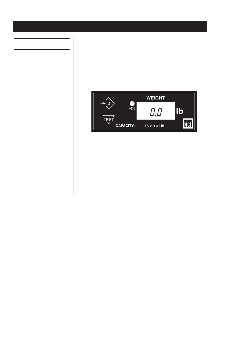
½" high, six-digit LCD.
Key panel with ZERO and TEST keys.
Remote display with 7 ft. cable.
Using the leveling bubble as a guide, adjust the
four adjustable feet to level the scale.
Initial automatic zero setting is ±10% of maxi-
mum capacity—active at power up. Manual zero
setting range is ±2% of maximum capacity—
active using the ZERO key.
Under capacity indication will be given with
dashes appearing on the bottom line of the
display whenever the display is more than 2
percent below the initial zero value.
Over capacity indication will be given with dashes
appearing on the top line of the display whenever
the weighed item exceeds 9 divisions over the
rated capacity of the unit. The scale will use the
initial zero value for reference for over capacity
determination.
Access to the calibration switch can be secured
with a lead-wire or pressure sensitive security
seal. The remote and primary indicators have no
metrological features that require the use of a
security seal.
The scale has 65,000 internal counts.
Sealing
Internal Counts
Construction
Under Capacity Limits
Display
Zero Window

Model 6712 Point-of-Sale Interface Scale User’s Manual
6
Communications
Dynamic Response The time from when weight is applied to the scale
to the time when stable weight is displayed:
0-1000d, 1.5 seconds
maximum mean average
1000d+, 2 seconds
maximum mean average
Factory default settings: 9600 baud, 8 data bits,
no parity, 1 stop bit.
Standard 9-pin pass through RS-232 interface
cable included. Not a null modem.
RS-232 bidirectional, configurable 2400, 4800 or
9600 baud. Transmits weight and scale status
whenever ASCII “W”<CR> is sent by a remote
device. Supports NCI Standard protocol only.

Model 6712 Point-of-Sale Interface Scale User’s Manual 7
Check container for any obvious evidence of
damage. Inspect the unit for shipping damage.
Immediately report any damage to the shipper.
1. Mount the unit on a stable, level surface that
is free from air currents and vibration. Be
sure the weigh platter does not touch any
adjacent surfaces.
2. To install the weigh platter flush with a
countertop, use the dimensions below to
guide your construction.
Scale Minimum Cutout
Dimensions Dimensions
W 10.4 in. (26.4 cm) W 11.1 in. (28.2 cm)
D 10.4 in. (26.4 cm) D 11.1 in. (28.2 cm)
H 2.5 in. (6.35 cm)*
*Adjustable to 3.0 in. (7.6 cm)
3. Loosen the jam nuts on the leveling feet.
Level the unit by using the level bubble under
the platter as a guide. Be sure all four feet
are in firm contact with the counter, then
tighten all jam nuts.
4. Make sure the power cord, display cable, etc.
are connected properly and are not touching
the live weighing surface.
5. Plug the unit into an appropriate voltage
outlet, properly grounded.
Initial Setup
Installing the Scale
Unpacking the Scale

Model 6712 Point-of-Sale Interface Scale User’s Manual
8
After the NCI Model 6712 is properly installed
and power is applied, the display will perform a
countdown test to insure all display segments are
functional.
After this test is completed, the display should
show zero (0.0).
If the display indicates a slightly “off” zero condi-
tion (either a number in the display or dashes at
the bottom of the display), press the ZERO key.
When the display shows 0.0, it is ready to weigh.
Place item or parcel on the weigh platter and the
weight will be displayed. This information can be
transmitted when requested by a remote device.
Operation
Operating Instructions
6712 Remote Display

Model 6712 Point-of-Sale Interface Scale User’s Manual 9
Entering Setup Mode
Access the MENU Mode by pressing switch 1
shown in Figure 1.
In the Menu Mode, there are three modes
available. They are as follows:
Diagnostic Mode (DIAG) – Used to test areas of
the scale’s function.
Configuration Mode (CONF) – Used to config-
ure the scale for your application.
Calibration Mode (CAL) – Used when calibrat-
ing the scale.
The structure for these menus is shown in Figure
2. Following that are the step-by-step instructions
for accessing the items within each menu.
Accessing the
Menu Mode
Figure 1
Switch Diagram
Diagnostics Mode
Diagnostic DIAG Mode The diagnostic (DIAG) mode menu lets you test
specific areas of the unit’s function. These areas
are:
Display (DISP) – Shows the version and revision
of the software, followed by a display segment
test.
Bottom view

Model 6712 Point-of-Sale Interface Scale User’s Manual
10
Figure 2
Menu Structure

Model 6712 Point-of-Sale Interface Scale User’s Manual 11
Input/Output (I-O) – To test the data I/O port,
install a loopback connector and press the test
button. The message PASS or FAIL is displayed.
This test requires a jumper (short) between
transmit and receive data lines.
Internal Counts (A/D) – Displays A/D data
internal counts (factory use only).
Follow these steps to access the tests in the
DIAG menu. Refer to Figure 2.
1. Press SW-1…
Display shows DIAG.
2. Press the TEST key. . .
DISP is displayed.
3. Press the TEST key to perform the display
test described earlier…
Display test is performed and shows
DISP after the test is completed.
4. Press the ZERO key to scroll to the I/O test...
I-O is displayed. This stands for the
Input/Output test.
5. With a loopback connector in place, press
the TEST key to perform the I/O test . . .
PASS or FAIL is displayed. If the test
fails, the unit may have a serial interface
failure.
6. Press the ZERO key to scroll to the internal
count test . . .
A/D is displayed. Tests A/D count data.
Step-by-Step Instructions
for Diag Mode
Return to normal
operating mode by
pressing the SW-1
switch.
Press the ZERO key
to scroll through the
lists of selections.
Press the TEST Key to
make a selection.
If you want to skip a
test, press the ZERO
key to scroll to the
next test.
If you press the ZERO
key to advance the
display message to
DONE, you can press
TEST to return to the
DIAG menu.
If you encounter any
failure in these tests,
contact technical
support.

Model 6712 Point-of-Sale Interface Scale User’s Manual
12
Configuration Mode
Step-by-Step Instructions
for CONF Mode
Return to normal
operating mode by
pressing the SW-1
switch.
The configuration (CONF) mode menu lets you
configure the scale to your specific application.
The items you can configure are as follows:
FILT (FILTER) – Adjusts the scale’s response to
fit environment. Factory default setting is FAST.
BAUD (BAUD) – Allows selection of appropriate
baud rate and parity for computer interface.
Factory default setting is 96-N.
1. Press SW-1. . .
DIAG is displayed.
2. Press the ZERO key. . .
CONF is displayed.
3. Press the TEST key. . .
FILT is displayed.
4. Press the TEST key. . .
The present filter setting is displayed. the
two choices. When the proper selection
7. Press the TEST key to perform this test…
Indicates internal A/D raw count. When
weight is applied, the count value should
increase proportionately.
8. Press the TEST key to stop the test . . .
The remaining selections are for viewing
current settings only. You can scroll
through the menu to verify the settings,
but to make changes, you must enter
configuration or calibration.

Model 6712 Point-of-Sale Interface Scale User’s Manual 13
is displayed, press the TEST key and
FILT will again be displayed.
5. Press the ZERO key. . .
BAUD is displayed.
6. Press the TEST key. . .
The present baud rate and parity are
displayed.
7. Press the ZERO key to scroll through the
nine choices. When the proper selection is
displayed, press the TEST key and the
baud rate and parity will be set as se-
lected…
FILT will again be displayed.
8. Press SW-1. . .
The unit returns to normal weighing mode.

Model 6712 Point-of-Sale Interface Scale User’s Manual
14
To abort the CAL
Mode at any time,
press the SW-1
switch.
Step-by-Step
Instructions for CAL
Mode
Calibration Mode
Calibration (CAL) Mode
Calibrating your
scale requires a
certified test weight
to ensure accurate
weighing.
The calibration (CAL) mode menu lets you
calibrate your scale. The items in the calibration
menu are as follows:
POUNDS/KILOGRAMS/OUNCES – Select the
unit of measure (lb, kg or oz).
CAPACITY – Select the capacity / resolution of
the scale.
Follow these steps to calibrate your scale. Refer
to Figure 2.
1. From the normal weighing mode, press SW-
1…
DIAG is displayed.
2. Press the ZERO key until…
CAL is displayed.
3. Press the TEST key to start calibration…
OUNCE is displayed.
4. If you want to change the unit of measure,
press the ZERO key to toggle between
OUNCE, LB or KILO. When the choice you
want is displayed, press the TEST key…
The current capacity selection is then
displayed.

Model 6712 Point-of-Sale Interface Scale User’s Manual 15
5. Press the ZERO key to scroll through the
available capacity selections. See Table 1 for
available capacity selections. When the
choice you want is displayed, press the
TEST key. . .
LOAD 0 is displayed.
lb kg oz
5 x 0.005 2.5 x 0.002 80 x 0.05
15 x 0.01 7 x 0.005 160 x 0.1
30 x 0.02 15 x 0.01 800 x 0.5
50 x 0.05 25 x 0.02 1600 x 1
100 x 0.1 50 x 0.05
150 x 0.05 75 x 0.02
150 x 0.1 75 x 0.05
6. Clear all weight from the weigh platter and
press the TEST key. After a brief wait…
LOAD 10 is displayed (or the current
capacity selected in Step 5). Alternate
calibration points can be chosen using
the ZERO key to scroll choices.
The NCI 6712 allows calibration using less
than full capacity weights. See Table 2 for a
list of the alternative weights that can be
used to calibrate your scale for its designed
capacity.
Make sure the weigh
platter and access
plate are on the scale
to establish proper
zero load.
Table 1
Capacity Selection

Model 6712 Point-of-Sale Interface Scale User’s Manual
16
Alternative
Capacity Calibration Weights
150 lb 10 lb, 50 lb
75 kg 10 kg, 50 kg
100 lb 10 lb, 50 lb
50 kg 10 kg, 25 kg
1600 oz (100 lb) 10 lb, 50 lb*
50 lb 10 lb, 25 lb
25 kg 2 kg, 5 kg
800 oz (50 lb) 10 lb, 25 lb*
30 lb 5 lb, 10, lb
15 kg 2 kg, 5 kg
7 kg 2 kg, 5 kg
160 oz (10 lb) 2 lb, 5 lb*
5 lb 1 lb, 2 lb
2.5 kg 1 kg
80 oz (5 lb) 1 lb, 2 lb*
* For convenience, span weight values are
prompted in POUNDS for ounce calibrations.
8. Place chosen calibration weight on the weigh
platter and press the TEST key…
After a brief wait, DONE is displayed.
9. Press SW-1…
The unit will perform a display countdown
and then return to normal weighing
mode.
The unit is now tested, configured and calibrated.
It is ready for use in your application.
Table 2
Alternative
Calibration Points
The calibration
weight should be
removed from the
weigh platter before
countdown com-
pletes.

Model 6712 Point-of-Sale Interface Scale User’s Manual 17
Review/Test Scale Settings
The TEST key located on the front panel lets you
perform some basic system diagnostics, as well
as review the current system settings without
having to access SW-1 switch inside the scale.
Press the ZERO key to
move to the next item
in the menu.
Press the TEST key to
select the displayed
item to run or view.
When finished running tests or viewing the
settings, press the ZERO key until DONE is
displayed. Then press the TEST key to return to
normal (i.e., weighing) mode of operation.
If you press and
release the TEST key,
the display will show
the scales model
number, version-
revision, and per-
forms a display test.
To review the current
system settings,
press and hold the
TEST until the display
prompts DISP.

Model 6712 Point-of-Sale Interface Scale User’s Manual
18
Communication
DE-9 Female Scale DE-9 Male Host
Pin Name Direction Pin Name Direction
1. JMP1 - 1. DCD IN
2. TXD OUT 2. RXD IN
3. RXD IN 3. TXD OUT
4. JMP 1 - 4. DTR OUT
5. GND REF 5. GND -
6. JMP 1 - 6. DSR IN
7. JMP 2 - 7. RTS OUT
8. JMP 2 - 8. CTS IN
9. NC - 9. RI IN
NOTE: JMP1 PINS 1, 4 and 6, and JMP 2 Pins 7
and 8 are internally jumpered inside the scale.
Error Codes
Any system errors detected by the scale will be
displayed as the letter E followed by a one-digit
error code. Press the TEST key to continue
operation. If a calibration error occurs, the only
way to clear the error is by recalibrating the unit.
The error codes are defined as follows:
Err-1 Calibration Error
Err-2 Configuration Error
Err-3 Initial Zero Error
Err-4 Zero Error
See the troubleshooting section at the end of this
manual.
The NCI 6712 comes factory configured as a
serial RS-232 interface device. There is one 9-
pin DE type female connector accessible at the
rear of the unit. The functional pinout of this
cable provided with your scale is that of a stan-
dard PC, which is as follows:

Model 6712 Point-of-Sale Interface Scale User’s Manual 19
Factory default settings: 9600 baud, 8 data bits,
no parity, 1 stop bit. Protocol is NCI standard
only.
Standard 9-pin pass through RS-232 interface
cable included. Not a null modem.
Symbol Key:
<ETX> End of Text Character (03 hex)
<LF> Line Feed Character (0A hex)
<CR> Carriage Return Character (0D hex)
<SP> Space (20 hex)
X Character from display including
minus sign
hhh Three status bytes
uu Unit of measure (lb, kg and oz) using
ANSI standard abbreviations)
Communication Setting
Command Scale Response Results
W<CR> <LF>xxxx.xxuu<CR> Returns decimal
<LF>hhh<CR><ETX> weight with units
or and scale status.
<LFxxxxxx<CR> Returns contents
<LF>hhh<CR><ETX> of display (other
than wt) and scale
status
S<CR> <LF>hhh<CR><ETX> Returns scale
status
Z<CR> <LF>hhh<CR><ETX> Scale is zeroed,
then status returns
All else <LF>?<CR><ETX> Unrecognized
command

Model 6712 Point-of-Sale Interface Scale User’s Manual
20
Troubleshooting
Perform each step in sequence to correct the
error condition. If the problem cannot be cor-
rected, contact your local Weigh-Tronix dealer.
No power (display is blank)
1. Check that the primary side of the cord is
plugged into the AC outlet, and the second-
ary side is properly connected to the power
jack on the back of the scale.
2. Replace power supply.
3. Replace the display board.
4. Replace the main board.
Missing or extra segments on display
1. Replace display board.
2. Replace the main board.
Scale will not return to zero, or incorrect
weight is displayed
1. Press the ZERO key.
2. Check for interference of weighing platform.
3. Power down, then power up the scale.
4. Recalibrate the scale.
5. Replace the load cell.
6. Replace the main board.
Display shows unrecognized characters
1. Check software PROM for proper insertion.
2. Check display cables for the proper connec-
tion.
3. Replace PROM
4. Replace the display board.
5. Replace the main board.
Display shows under “_ _ _” dashes
(Indicates that the scale is below zero or under capacity.)
1. Verify that the weigh platter is on the scale.
2. Press the ZERO key.
3. Power down, remove any items from the
platter, and then power up the scale.
4. Recalibrate the scale.
5. Replace the load cell.
Symptom and
Recommended Action
This manual suits for next models
1
Table of contents
Other NCI Scale manuals