Model 7620U Bench Scale User’s Manual 5
Power Requirements
Operating Temperature
Construction
Overload Protection
Display
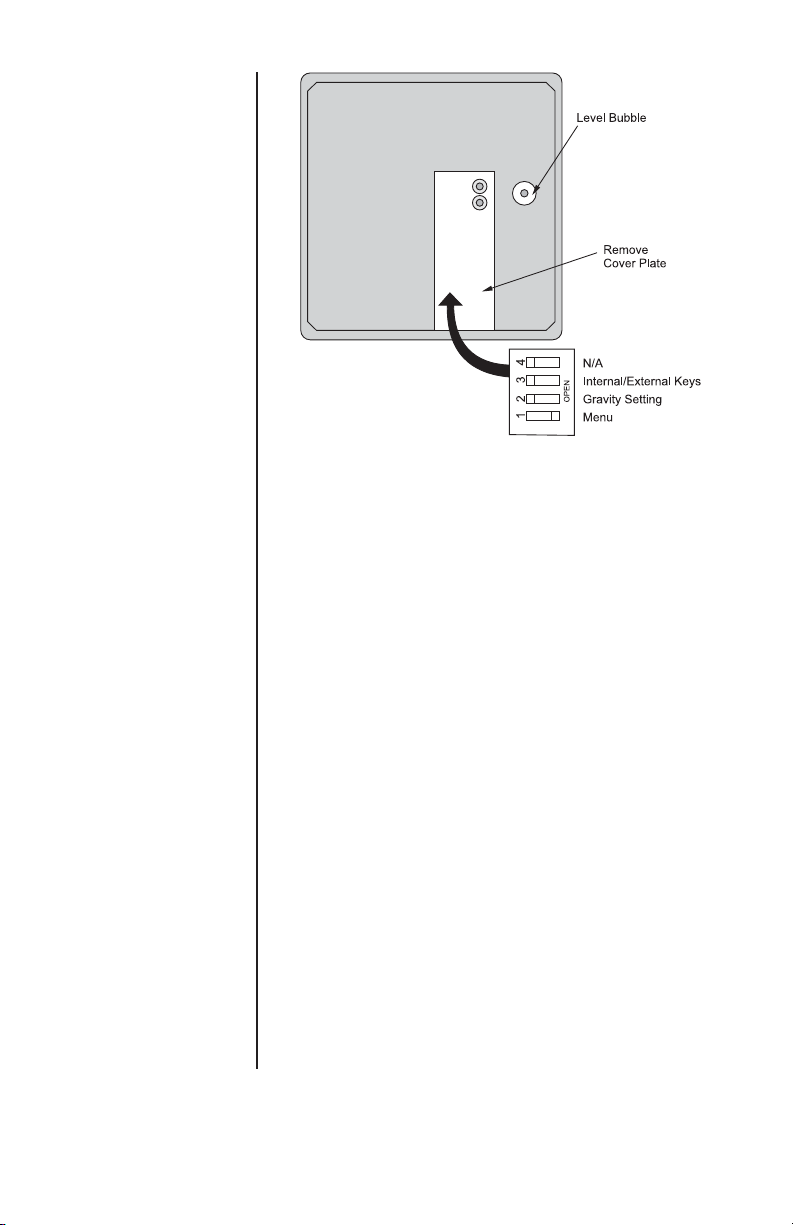
Scale Leveling
Zero Window
Under Capacity Limits
Over Capacity Limits
Sealing
0.1 amp maximum
+5º C to + 40º C
10% to 95% RH (non-condensing)
Die cast aluminum base and load bridge.
Plastic ABS weigh platter
Aluminum quartz digital load cell
Adjustable center stop
Fixed corner stops
400% static loading
200% dynamic loading
13mm (0.5") high seven-digit LCD
Key panel with ZERO and F1 function keys
Optional remote display with 2m (7ft) cable
Level bubble under weigh platter
Adjustable feet in each corner
Automatic zero setting is ±10% of maximum
capacity—active at power up. Manual zero
setting range is ± 2% of maximum capacity—
active using the ZERO key.
Under capacity indication will be given with
dashes appearing on the bottom line of the
display whenever the display is more than 2
percent below the initial zero value.
Over capacity indication will be given with dashes
appearing in the upper line of the display when-
ever the weighed item exceeds 9 divisions over
the rated capacity of the unit. The scale will use
the initial zero value for reference for over
capacity determination.
Access to the calibration switch can be secured
with a lead wire or pressure sensitive security
seal. The remote and primary indicators have no
metrological features that require the use of a
security seal.