manuals.online logo
Brands
  1. Home
  2. •
  3. Brands
  4. •
  5. NEC
  6. •
  7. Projector
  8. •
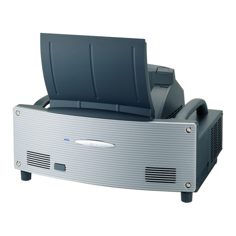
  9. NEC MultiSync VT440 Installation and user guide

NEC MultiSync VT440 Installation and user guide

Other manuals for MultiSync VT440

3

This manual suits for next models

3

Other NEC Projector manuals

NEC NP115 Series User manual

NEC

NEC NP115 Series User manual

NEC UM383WL User manual

NEC

NEC UM383WL User manual

NEC LT260 Series User manual

NEC

NEC LT260 Series User manual

NEC M230X User manual

NEC

NEC M230X User manual

NEC P506QL User manual

NEC

NEC P506QL User manual

NEC NP62 Series User manual

NEC

NEC NP62 Series User manual

NEC NP-V300W User manual

NEC

NEC NP-V300W User manual

NEC LT50 - User manual

NEC

NEC LT50 - User manual

NEC NP1150 XGA User manual

NEC

NEC NP1150 XGA User manual

NEC VT460 User manual

NEC

NEC VT460 User manual

NEC HT1000 Series User manual

NEC

NEC HT1000 Series User manual

NEC P502WL-2 User manual

NEC

NEC P502WL-2 User manual

NEC NP210 User manual

NEC

NEC NP210 User manual

NEC PE401H User manual

NEC

NEC PE401H User manual

NEC PH1202HL User manual

NEC

NEC PH1202HL User manual

NEC NP3151W WXGA User manual

NEC

NEC NP3151W WXGA User manual

NEC M300X Series User manual

NEC

NEC M300X Series User manual

NEC NP64 Series Configuration guide

NEC

NEC NP64 Series Configuration guide

NEC LT380 - MultiSync XGA LCD Projector User manual

NEC

NEC LT380 - MultiSync XGA LCD Projector User manual

NEC PA521U User manual

NEC

NEC PA521U User manual

NEC NP-02HD User manual

NEC

NEC NP-02HD User manual

NEC NC800C User manual

NEC

NEC NC800C User manual

NEC WT610 Series User manual

NEC

NEC WT610 Series User manual

NEC NP600 Series User manual

NEC

NEC NP600 Series User manual

Popular Projector manuals by other brands

Eiki LC-X985 Specification sheet

Eiki

Eiki LC-X985 Specification sheet

InFocus LitePro 610 quick start

InFocus

InFocus LitePro 610 quick start

Epson EH-TW5900 datasheet

Epson

Epson EH-TW5900 datasheet

FOREVER MLP-100 manual

FOREVER

FOREVER MLP-100 manual

Toshiba TDP-MT8U Specifications

Toshiba

Toshiba TDP-MT8U Specifications

Mitsubishi XD500U specification

Mitsubishi

Mitsubishi XD500U specification

Kodak Ektapro 3020 Illustrated parts list

Kodak

Kodak Ektapro 3020 Illustrated parts list

Toshiba TDP-EW25U Specifications

Toshiba

Toshiba TDP-EW25U Specifications

Barco iQ PRO G500 supplementary guide

Barco

Barco iQ PRO G500 supplementary guide

Philips LC1341 user guide

Philips

Philips LC1341 user guide

Epson PowerLite 1266 user guide

Epson

Epson PowerLite 1266 user guide

MAGINON DLP 1400S user manual

MAGINON

MAGINON DLP 1400S user manual

Toshiba TLP-380 owner's manual

Toshiba

Toshiba TLP-380 owner's manual

Philips PicoPix PPX2480/EU user manual

Philips

Philips PicoPix PPX2480/EU user manual

Hitachi CP-X605 Series Specifications

Hitachi

Hitachi CP-X605 Series Specifications

Optoma TW1692 user manual

Optoma

Optoma TW1692 user manual

Kodak EKTAPRO instruction manual

Kodak

Kodak EKTAPRO instruction manual

Optoma Optoma PRO150S datasheet

Optoma

Optoma Optoma PRO150S datasheet

manuals.online logo
manuals.online logoBrands
  • About & Mission
  • Contact us
  • Privacy Policy
  • Terms and Conditions

Copyright 2025 Manuals.Online. All Rights Reserved.

Visual Systems Division
Technical Bulletin
MultiSyncVT440/540 Installation Data
Desktop and Ceiling Mount Rev. 1.5
Page 1
Contents
Lens Specs, Notes and Formulas Page 1
Projection Distances and Screen Sizes
Desktop Setup Page 2
Ceiling Mount Installation Page 3
Cabinet Dimensions
Top, Backt and Left Side Page 4
Bottom, Front and Right Side Page 5
Quick Release Ceiling Mount Dimensions Page 6
Timing Chart Page 7
PC Control Codes Page 8
Lens Specifications
Manual Zoom, Manual Focus F2.0 –2.3 f = 35.8 –43.0 mm
Screen Sizes: 25" -300" diagonal
Throw Ratio: Full Wide: 1.90–1.96 (see charts) Full Tele: 2.28-2.35 (see charts)
Offset Angle: Full Wide: 9.01 -8.72 (see charts) Full Tele: 7.53 -7.28 (see charts)
Notes
§For Screen Sizes of 25 to 300 inches not indicated on the projection tables, use the formulas below.
§If the figures on the tables do not match the figures in the formulas, use the figures in the table.
§The ceiling must be strong enough to support the LCD projector and the installation must be in accordance with any local
building codes.
•All calculations using Screen Diagonal are based on 4:3 aspect ratio.
•Distances are in inches, for millimeters multiply by 25.4.
•Distances may vary ±5%.
Formulas
Units: Inches (for millimeters multiply final number by 25.4)
D = Screen Diagonal (4:3)
H= D x 0.8 H= Screen Width (4:3)
V= D x 0.6 V= Screen Height (4:3)
M= 1.25H / 0.92205 M = Projection magnification
C(Wide) = 1.4516M –1.715 C= Horizontal throw distance
C(Tele) = C (Wide) x 1.2
E= 0.2165M + 2.476 E= Vertical distance between projector feet and screen center
D = 0.0571M –2.476 D= Vertical distance between projector feet and screen bottom
B= 0.2165M B= Vertical distance between lens center and screen center
F= 0.0571M F= Vertical distance between lens center and screen top
αα (Wide) = tan-1(B / C (wide)) αα = Throw angle
αα (Tele) = tan-1(B / C (tele))
Visual Systems Division
Technical Bulletin
MultiSyncVT440/540 Installation Data
Desktop and Ceiling Mount Rev. 1.5
Page 2
Projection Distance and Screen Size for Desktop
The following shows the proper relative positions of the projector and screen. Refer to the table to determine the position of
installation.
Distances are in inches. For millimeters multiply by 25.4.
Desktop Setup
C
D
α
Throw Distance
Screen Top
Screen Ctr
E
Projector Feet
PJ Feet
Scrn Bottom
Distance Chart
Note:
For screen sizes of 25 to 300 inches not indicated on the projection tables, use the formulas on page 1.
Cαα ED
Diagonal Width Height wide - tele wide - tele
40" 32" 24" 61.3" - 73.5" 8.93° - 7.46° 12.1" 0.1"
60" 48" 36" 92.7" - 111.3" 8.85° - 7.39° 16.9" 1.3"
67" 53.6" 40.2" 103.8" - 124.5" 8.83° - 7.38° 18.6" 1.8"
72" 57.6" 43.2" 111.6" - 134.0" 8.82° - 7.37° 19.8" 2.1"
84" 67.2" 50.4" 130.5" - 156.6" 8.80° - 7.35° 22.7" 2.9"
90" 72" 54" 140.0" - 168.0" 8.79° - 7.35° 24.1" 3.2"
100" 80" 60" 155.7" - 186.9" 8.78° - 7.34° 26.5" 3.9"
120" 96" 72" 187.2" - 224.6" 8.77° - 7.32° 31.3" 5.1"
150" 120" 90" 234.4" - 281.3" 8.75° - 7.31° 38.6" 7.1"
180" 144" 108" 281.7" - 338.0" 8.74° - 7.30° 45.8" 9.0"
210" 168" 126" 328.9" - 394.7" 8.73° - 7.30° 53.0" 10.9"
240" 192" 144" 376.1" - 451.4" 8.73° - 7.29° 60.2" 12.8"
270" 216" 162" 423.4" - 508.0" 8.72° - 7.29° 67.4" 14.7"
300" 240" 180" 470.6" - 564.7" 8.72° - 7.28° 74.6" 16.6"
Screen Size
Visual Systems Division
Technical Bulletin
MultiSyncVT440/540 Installation Data
Desktop and Ceiling Mount Rev. 1.5
Page 3
Projection Distance and Screen Size for Ceiling Mount Installation
The following diagram shows the relationship between projector position and the screen.
Distances are in inches. For millimeters multiply by 25.4.
Ceiling Mount Installation
C
α
F
B
Screen Ctr
Scrn Bottom
Screen Top
Lens Ctr
1.3"
Lens Offset from
MountingPipe
5.27"
Throw Distance 5.52"
Distance Chart
Note:
For screen sizes of 25 to 300 inches not indicated on the projection tables, use the formulas on page 1.
Cαα BF
Diagonal Width Height wide - tele wide - tele
40" 32" 24" 61.3" - 73.5" 8.93° - 7.46° 9.6" 2.5"
60" 48" 36" 92.7" - 111.3" 8.85° - 7.39° 14.4" 3.8"
67" 53.6" 40.2" 103.8" - 124.5" 8.83° - 7.38° 16.1" 4.3"
72" 57.6" 43.2" 111.6" - 134.0" 8.82° - 7.37° 17.3" 4.6"
84" 67.2" 50.4" 130.5" - 156.6" 8.80° - 7.35° 20.2" 5.3"
90" 72" 54" 140.0" - 168.0" 8.79° - 7.35° 21.7" 5.7"
100" 80" 60" 155.7" - 186.9" 8.78° - 7.34° 24.1" 6.3"
120" 96" 72" 187.2" - 224.6" 8.77° - 7.32° 28.9" 7.6"
150" 120" 90" 234.4" - 281.3" 8.75° - 7.31° 36.1" 9.5"
180" 144" 108" 281.7" - 338.0" 8.74° - 7.30° 43.3" 11.4"
210" 168" 126" 328.9" - 394.7" 8.73° - 7.30° 50.5" 13.3"
240" 192" 144" 376.1" - 451.4" 8.73° - 7.29° 57.7" 15.2"
270" 216" 162" 423.4" - 508.0" 8.72° - 7.29° 65.0" 17.1"
300" 240" 180" 470.6" - 564.7" 8.72° - 7.28° 72.2" 19.0"
Screen Size
Visual Systems Division
Technical Bulletin
MultiSyncVT440/540 Installation Data
Desktop and Ceiling Mount Rev. 1.5
Page 4
Cabinet Dimensions
The following diagrams show the cabinet dimensions for the MultiSync VT440/540.
Dimensions are in inches. For millimeters multiply by 25.4.
4.03
4.57
9.57
11.68
Visual Systems Division
Technical Bulletin
MultiSyncVT440/540 Installation Data
Desktop and Ceiling Mount Rev. 1.5
Page 5
Cabinet Dimensions (continued)
The following diagrams show the cabinet dimensions for the MultiSync VT440/540.
Dimensions are in inches. For millimeters multiply by 25.4.
M4 * MAX10
M4 * MAX10
0.15 0.15
0.39
2.44
0.79 6.40
1.89
1.18
0.35
0.39
0.53
0.098
0.59
0.079 2.28 1.31
0.236
7.40
0.39
7.24
2.02
0.098
0.197
Visual Systems Division
Technical Bulletin
MultiSyncVT440/540 Installation Data
Desktop and Ceiling Mount Rev. 1.5
Page 6
Quick Release Ceiling Mount Dimensions (Model #: VT40CM)
The following diagrams show the quick release ceiling mount dimensions for the MultiSync VT440/540.
Dimensions are in inches. For millimeters multiply by 25.4.
3.0
TYP
TYP
TYP
1.94
∅
∅
∅
.41 TYP
.34 TYP
5° UP
15° DOWN
68°
34°
3.75
3.75
8.00
8.00
4.00
4.00
22°
Visual Systems Division
Technical Bulletin
MultiSyncVT440/540 Installation Data
Desktop and Ceiling Mount Rev. 1.5
Page 7
Timing Chart
Y/N Signal Resolution Refresh Rate Frequency H. Dot Clock
( Dots ) ( Hz ) ( kHz ) ( MHz)
Y NTSC 640 x 480 60 15.734 –
YPAL 768 x 576 50 15.625 –
YSECAM 768 x 576 50 15.625 –
YVESA 640 x 480 59.94 31.47 25.175
YIBM 640 x 480 60 31.47 25.175
YMAC 640 x 480 60 31.47 25.175
YMAC 640 x 480 66.67 34.97 31.334
YMAC 640 x 480 66.67 35 30.24
YVESA 640 x 480 72.81 37.86 31.5
YVESA 640 x 480 75 37.5 31.5
YIBM 640 x 480 75 39.375 31.49
YVESA 640 x 480 85.01 43.269 36
YIBM 720 x 350 70.09 31.469 28.322
YVESA 720 x 400 85.04 37.927 35.5
YIBM 720 x 350 87.85 39.44 35.5
YIBM 720 x 400 87.7 39.375 35.5
YVESA 800 x 600 56.25 35.16 36
YVESA 800 x 600 60.32 37.879 40
YVESA 800 x 600 72.19 48.077 50
YVESA 800 x 600 75 46.88 49.5
YVESA 800 x 600 85.06 53.674 56.25
#Y MAC 832 x 624 74.55 49.725 57.283
#Y VESA 1024 x 768 43 Interlace 35.5 44.9
#Y VESA 1024 x 768 60 48.363 65
#Y VESA 1024 x 768 70.07 57.476 75
#Y IBM 1024 x 768 72.03 58.131 79
#Y MAC 1024 x 768 74.93 60.241 80
#Y VESA 1024 x 768 75.03 60.023 78.75
#Y VESA 1024 x 768 85 68.677 94.5
##Y VESA 1152 x 864 75 67.5 108
##Y MAC 1152 x 870 75.06 68.681 100
##Y SUN 1152 x 900 65.95 61.796 92.94
##Y SGI 1152 x 900 76.05 71.736 105.6
##Y VESA 1280 x 960 60 60 108
##Y SGI 1280 x 1024 60 63.9 107.35
##Y VESA 1280 x 1024 60.02 63.981 108
##Y MAC 1280 x 1024 60.38 64.31 107
##Y MAC 1280 x 1024 65.2 69.9 118.5
##Y HP 1280 x 1024 72.01 78.125 135
##Y SUN 1280 x 1024 76.11 81.13 135
##Y VESA 1280 x 1024 75.03 79.976 135
##Y VESA 1280 x 1024 85.02 91.146 157.5
##Y HDTV (1080i) 1920 x 1080 60 Interlace 33.75 74.25
##Y HDTV (720p) 1280 x 720 60 Progr 45 74. 25
##Y SDTV (480p) 720 x 483 59.94 Progr 31.47 27
#Y: Images in above flagged with # and Y are compressed with Advanced AccuBlend on VT440.
##Y: Images in above flagged with ## and Y are compressed with Advanced AccuBlend on VT540.
NOTE1: Some composite sync signals may not be displayed correctly.
NOTE2: Signals other than those specified in the table above may not be displayed correctly. If this should happen, change the refresh
rate or resolution on your PC. Refer to Display Properties help section of your PC for procedures.
Visual Systems Division
Technical Bulletin
MultiSyncVT440/540 Installation Data
Desktop and Ceiling Mount Rev. 1.5
Page 8
PC Control Codes
Function Code Data
POWER ON 02H 00H 00H 00H 00H 02H
POWER OFF 02H 01H 00H 00H 00H 03H
INPUT SELECT RGB 02H 03H 00H 00H 02H 01H 01H 09H
INPUT SELECT VIDEO 02H 03H 00H 00H 02H 01H 06H 0EH
INPUT SELECT S-VIDEO 02H 03H 00H 00H 02H 01H 0BH 13H
PICTURE MUTE ON 02H 10H 00H 00H 00H 12H
PICTURE MUTE OFF 02H 11H 00H 00H 00H 13H
SOUND MUTE ON 02H 12H 00H 00H 00H 14H
SOUND MUTE OFF 02H 13H 00H 00H 00H 15H
ON SCREEN MUTE ON 02H 14H 00H 00H 00H 16H
ON SCREEN MUTE OFF 02H 15H 00H 00H 00H 17H
Cable Connection
Communication Protocol:
Baud Rate: 38400 bps
Data Length: 8 bits
Parity: No Parity
Stop Bit: One bit
X on/off: None
Communications: Full duplex
PC Control Connector (DIN-8P)
8 7 6
543
2 1
To GND of PC To TxD of PC
To RxD of PC
NOTE: Pins 2, 3, 5, 6 and 8 are used inside the projector.