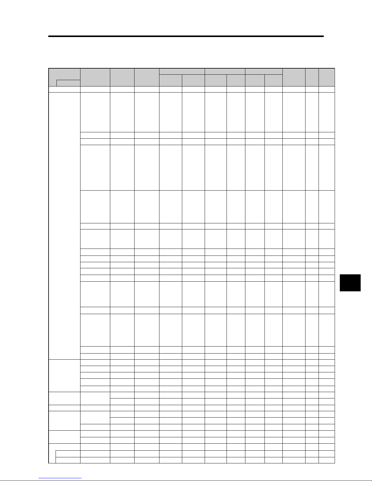
NEC PX-42VR5W User manual

PX-42VR5W
(42Wide VGA)
Model Information
Modell-Informationen
Informations modèle
Información del modelo
Informazioni sul modello
нформация о модели

E-1
Specifications
Screen Size 921(H)518(V) mm
36.3"(H)20.4"(V) inches
diagonal 42"
Aspect Ratio 16 : 9
Resolution 853(H)480(V) pixels
Pixel Pitch 1.08(H)1.08(V) mm
0.04"(H)0.04"(V) inches
Color Processing 4,096 steps, 68.7 billion colors
Signals
Synchronization Range Horizontal : 15.5 to 110 kHz
(automatic : step scan)
Vertical : 50.0 to 120 Hz
(automatic : step scan)
Input Signals RGB, NTSC (3.58/4.43), PAL (B,G,M,N),
PAL60, SECAM, HD*1, DVD*1, DTV*1
Input Terminals
RGB
Visual 1 (Analog) mini D-sub 15-pin1
Visual 2 (Analog) BNC (R, G, B, H/CS, V)1*2
Visual 3 (Digital) DVI-D 24-pin1*3
Video
Visual 1 BNC1
Visual 2 RCA-pin1
Visual 3 S-Video: DIN 4-pin1
DVD/HD/DTV
Visual 1 RCA-pin (Y, PB[CB], PR[CR])1*1
Visual 2 BNC (Y, PB[CB], PR[CR])1*1, *2
Visual 3 DVI-D 24-pin1*3
Audio Stereo RCA3(Selectable)
External Control D-sub 9-pin1(RS-232C)
Sound output 8W+8W at 6 ohm
Power Supply AC100-240V 50/60Hz
Current Rating 4.5A (maximum)
Power Consumption 270W (typical)
Dimensions 1018 (W)610 (H)89(D) mm
40 (W)24 (H)3.5 (D) inches
Weight 28.5 kg / 62.8 lbs (without stand)
Environmental Considerations
Operating Temperature 0°C to 40°C / 32°F to 104°F
Humidity 20 to 80% (no condensation)
Altitude 0 to 2800 m / 0 to 9180 feet
Storage Temperature -10°C to 50°C / 14°F to 122°F
Humidity 10 to 90% (no condensation)
Altitude 0 to 3000 m / 0 to 9840 feet
Front Panel User Controls Power on/off, Input source select,
Volume up/down, OSM control
Remote Control Functions
Power on/off, Input source select, OSM
control,Volume up/down, Cursor (UP,
DOWN,LEFT, RIGHT), Zoom up/down,
Picture control buttons
OSM Functions PICTURE (PICTURE MEMORY/CONTRAST/
BRIGHTNESS/SHARPNESS/COLOR/TINT/
NR/COLOR TEMP./WHITE BALANCE/
GAMMA/LOWTONE/SETUPLEVEL/COLOR
TUNE/CINEMA MODE/PICTURE MODE),
AUDIO (BASS/TREBLE/BALANCE/AUDIO
INPUT1/AUDIO INPUT2/AUDIO INPUT3),
IMAGE ADJUST (ASPECT MODE/V-
POSITION/H-POSITION/V-HEIGHT/H-
WIDTH/AUTO PICTURE/FINE PICTURE/
PICTURE ADJ.),
SET UP (LANGUAGE*/BNC INPUT/D-SUB
INPUT/HD SELECT/RGB SELECT/DVI SET
UP/COLOR SYSTEM/BACK GROUND/GRAY
LEVEL/S1/S2/DISPLAYOSM/OSMADJ./ALL
RESET), FUNCTION (POWER MGT./INPUT
SKIP/PDPSAVER [PEAK BRIGHT / ORBITER
/ INVERSE/WHITE / SCREEN WIPER / SOFT
FOCUS / OSM ORBITER / OSM
CONTRAST]), SIGNAL INFO.
The features and specifications may be subject to change without
notice.
*1HD/DVD/DTV input signals supported on this
system
480P (60 Hz) 480I (60 Hz)
525P (60 Hz) 525I (60 Hz)
576P (50 Hz) 576I (50 Hz)
625P (50 Hz) 625I (50 Hz)
720P (60 Hz) 1035I (60 Hz)
1080I (50 Hz) 1080I (60 Hz)
*2The 5-BNC connectors are used as RGB/PC2 and
HD/DVD2 input. Select one of them under “BNC
INPUT”.
*3Compatable with HDCP.
Supported Signals
• 640480P @ 59.94/60Hz • 19201080I @ 50Hz
• 1280720P @ 59.94/60Hz • 720576P @ 50Hz
• 19201080I @ 59.94/60Hz • 1440 (720)576P @ 50Hz
• 720480P @ 59.94/60Hz
• 1440 (720)480I @ 59.94/60Hz
Note:Insomecases a signalonthe plasma monitormaynotbe displayed
properly. The problem may be an inconsistency with standards from
the source equipment (DVD, Set-top box, etc...). If you do experience
sucha problem please contact your dealer andalso themanufacturer of
the source equipment.
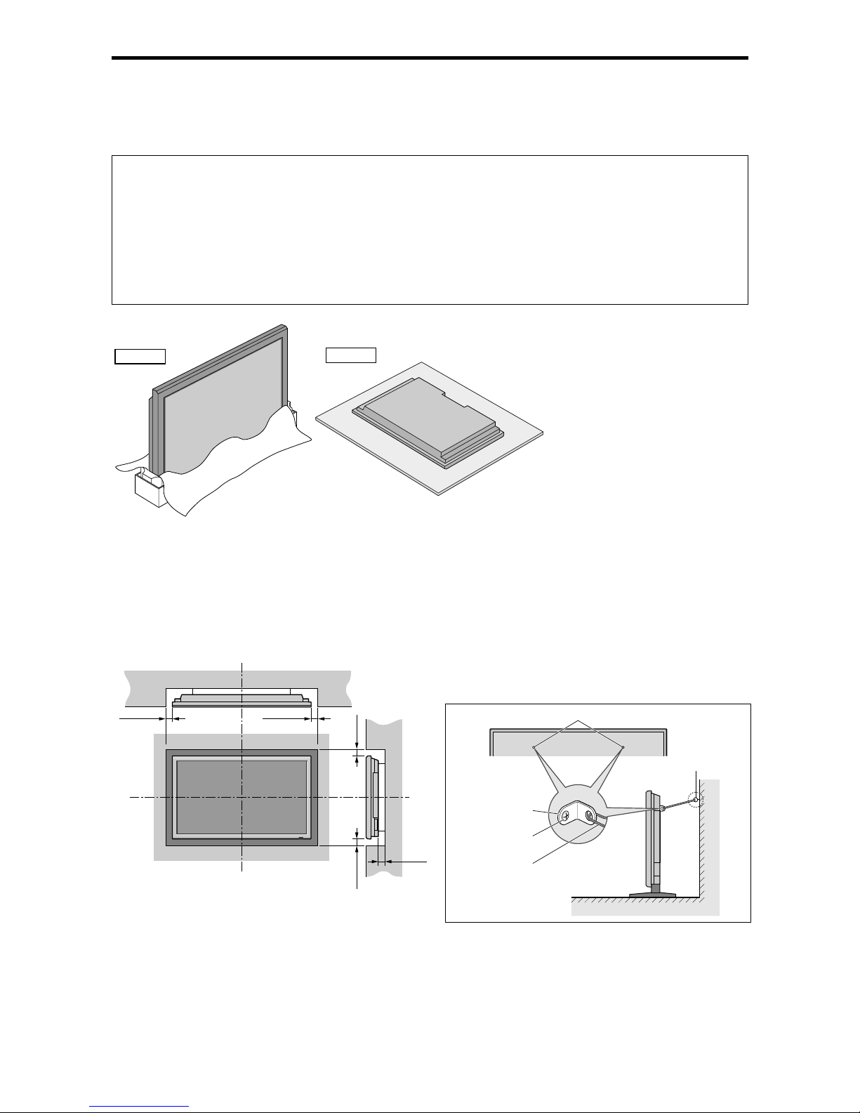
Units are in mm
(inch)
89
(3.5")
35
(1.38") 54
(2.13")
1018 (40")
610 (24")
921 (36.3")
518 (20.4")
*English, German, French, Italian, Spanish,
Swedish, Chinese, Russian
Other Features Motion compensated 3D Scan Converter (NTSC,
PAL, 480I, 576I, 525I, 625I, 1035I, 1080I), 2-3
pull down Converter (NTSC, 480I, 525I, 1035I,
1080I (60Hz)), 2-2 pull down Converter (PAL,
576I, 625I, NTSC, 480I, 525I), Digital Zoom
Function (100-900% Selectable), Self Diagnosis,
Image Burn reduction tools (PEAK BRIGHT,
ORBITER, INVERSE/WHITE, SCREEN
WIPER), Color Temperature select (high/middle/
middle low/low, user has 4 memories), Auto
Picture, Input Skip, Color Tune, Low Tone (3
mode), Gamma Correction (4 mode), Plug and
play (DDC1, DDC2b, RGB3: DDC2b only)
Accessories Remote control with twoAAAbatteries, Power
cord, Manuals, Safety metal fittings, Ferrite cores,
Bands, Cable clamps, HDMI-DVI cable
Regulations
Meets EMC Directive
(EN55022 Class B, EN55024, EN61000-3-2,
EN61000-3-3)
Meets Low Voltage Directive
(EN60950 and EN60065, IEC60950 and
IEC60065, SEMKO Approved)
Meets AS/NZS CISPR 22:2002 Class B
Bezel color is silver.
For the operation of your plasma monitor,
refer to “Operation Manual”.

Table of Signals Supported
E-2
Supported resolution
•When the screen mode is NORMAL, each signal is converted to a 640 dots480 lines signal. (Except for *2, *4)
•When the screen mode is ANAMORPHIC, each signal is converted to a 853 dots480 lines signal. (Except for *3)
Computer input signals supported by this system
Screen mode
Dots lines
640400
640480
848480
852480*1
800600
1024768
1152864
1280768
1280768*9
1280800*9
1280854*9
1360765
1360768
1376768
12801024
16801050*9
16001200
19201200*9
19201200RB
*9
640480
832624
1024768
1152870
1440900*9
12801024
12801024
1152900
12801024
1024768
12801024
768576
640480
Vertical
frequency
(Hz)
70.1
59.9
72.8
75.0
85.0
100.4
120.4
60.0
60.0
56.3
60.3
72.2
75.0
85.1
99.8
120.0
60.0
70.1
75.0
85.0
100.6
75.0
56.2
59.8
69.8
60.0
60.0
60.0
60.0
59.9
60.0
75.0
85.0
100.1
60.0
60.0
65.0
70.0
75.0
85.0
60.0
60.0
66.7
74.6
74.9
75.1
60.0
60.0
71.2
72.0
66.0
76.0
76.1
60.0
60.0
50.0
59.9
Horizontal
frequency
(kHz)
31.5
31.5
37.9
37.5
43.3
51.1
61.3
31.0
31.7
35.2
37.9
48.1
46.9
53.7
63.0
75.7
48.4
56.5
60.0
68.7
80.5
67.5
45.1
48.0
56.0
49.7
53.1
47.7
47.7
48.3
64.0
80.0
91.1
108.5
65.3
75.0
81.3
87.5
93.8
106.3
74.6
74.0
35.0
49.7
60.2
68.7
56.0
64.6
75.1
78.1
61.8
71.7
81.1
49.7
63.9
31.4
31.5
NORMAL
(4:3)
YES*2*3
YES*3
YES*3
YES*3
YES*3
YES*3
YES*3
––
––
YES
YES
YES
YES
YES
YES
YES
YES
YES
YES
YES
YES
YES
––
––
––
––
––
––
––
––
YES*4
YES*4
YES*4
YES*4
––
YES
YES
YES
YES
YES
––
––
YES*3
YES
YES
YES
––
YES*4
YES*4
YES*4
YES
YES
YES*4
YES
YES*4
YES*7
YES*7
ANAMORPHIC
(16:9)
YES
YES
YES
YES
YES
YES
YES
YES*3
YES*3
YES
YES
YES
YES
YES
YES
YES
YES
YES
YES
YES
YES
YES
YES
YES
YES
YES
YES
YES
YES
YES
YES
YES
YES
YES
YES
YES
YES
YES
YES
YES
YES
YES
YES
YES
YES
YES
YES
YES
YES
YES
YES
YES
YES
YES
YES
YES*7
YES*7
RGB
select*5
––
STILL
––
STILL
––
––
––
WIDE2
WIDE1
STILL
STILL
––
––
––
––
––
STILL
––
STILL
––
––
STILL
WIDE1
WIDE3
WIDE1
WIDE1
WIDE2
WIDE1
WIDE1
WIDE2
STILL
––
––
––
WIDE4
––
––
––
––
––
WIDE2
WIDE3
––
––
WIDE1
WIDE1
––
––
––
––
––
––
––
––
––
––
MOTION
Apple
Macintosh*6, *8
Horizontal
NEG
NEG
NEG
NEG
NEG
NEG
NEG
POS
NEG
POS
POS
POS
POS
POS
POS
POS
NEG
NEG
POS
POS
NEG
POS
POS
POS
NEG
NEG
NEG
POS
POS
NEG
POS
POS
POS
POS
NEG
POS
POS
POS
POS
POS
NEG
NEG
Sync on G
Sync on G
Sync on G
Sync on G
NEG
NEG
NEG
––
C Sync
C Sync
C Sync
––
––
NEG
NEG
Work Station
(EWS4800)
*8
WorkStation (HP)
*8
Work Station
(SUN)
*8
Work Station
(SGI)
IDC-3000G
Signal Type
IBM PC/AT
compatible
computers*8
Vertical
NEG
NEG
NEG
NEG
NEG
NEG
NEG
POS
NEG
POS
POS
POS
POS
POS
POS
POS
NEG
NEG
POS
POS
NEG
POS
POS
NEG
POS
NEG
NEG
POS
POS
POS
POS
POS
POS
POS
NEG
POS
POS
POS
POS
POS
NEG
NEG
Sync on G
Sync on G
Sync on G
Sync on G
NEG
NEG
NEG
––
C Sync
C Sync
C Sync
––
––
NEG
NEG
Sync Polarity Presence
Horizontal
YES
YES
YES
YES
YES
YES
YES
YES
YES
YES
YES
YES
YES
YES
YES
YES
YES
YES
YES
YES
YES
YES
YES
YES
YES
YES
YES
YES
YES
YES
YES
YES
YES
YES
YES
YES
YES
YES
YES
YES
YES
YES
––
––
––
––
YES
YES
YES
––
––
––
––
––
––
YES
YES
Vertical
YES
YES
YES
YES
YES
YES
YES
YES
YES
YES
YES
YES
YES
YES
YES
YES
YES
YES
YES
YES
YES
YES
YES
YES
YES
YES
YES
YES
YES
YES
YES
YES
YES
YES
YES
YES
YES
YES
YES
YES
YES
YES
––
––
––
––
YES
YES
YES
––
––
––
––
––
––
YES
YES
PAL625P
NTSC525P
Model DVI
NO
YES
YES
YES
YES
YES
YES
YES
YES
YES
YES
YES
YES
YES
YES
YES
YES
YES
YES
YES
YES
YES
NO
YES
YES
YES
YES
NO
YES
YES
YES
YES
YES
NO
YES
YES
NO
NO
NO
NO
––
YES
NO
NO
NO
NO
YES
YES
YES
YES
YES
YES
YES
YES
YES
NO
NO
Memory
4
5
7
8
9
41
42
19
17
11
12
13
14
15
43
44
24
25
26
27
45
51
52
80
66
21
37
22
22
53
29
30
40
47
38
54
55
56
57
58
81
88
6
16
28
39
89
29
48
59
60
61
30
62
29
31
32

E-3
Important Information
*1 Only when using a graphic accelerator board that is capable of displaying 852480.
*2 Display only 400 lines with the screen center of the vertical orientation located at the center.
*3 The picture is displayed in the original resolution. The picture will be compressed for other signals.
*4 Aspect ratio is 5:4. This signal is converted to a 600 dots480 lines signal.
*5 Normally the RGB select mode suite for the input signals is set automatically. If the picture is not displayed properly, set the RGB mode
prepared for the input signals listed in the table above.
*6 To connect the monitor to Macintosh computer, use the monitor adapter (D-Sub 15-pin) to your computer's video port.
*7 Other screen modes (ZOOM and STADIUM) are available as well.
*8 When viewing a moving picture at a vertical frequency greater than 65Hz, the picture may sometimes be unstable (jumpy). If this occurs,
please set the refresh rate of the external equipment to 60Hz.
Toview 480I@60Hz (480 interlaced lines, 60Hzrefresh rate) or 576I@50Hz (567 interlaced lines, 50Hz refresh rate) when sync polarity
is “Sync on Green”, set “RGB SELECT”to “MOTION”.
*9 CVT standard compliant.
NOTE:
•Whilethe input signals comply with theresolutionlisted inthe table above, you may haveto adjust the position and sizeof the
picture or the fine picture because of errors in synchronization of your computer.
•Thismonitorhas aresolutionof 853dots
480lines.It isrecommendedthat the inputsignal beVGA,wide VGAorequivalent.
•With digital input some signals are not accepted.
•The sync may be disturbed when a nonstandard signal other than the aforementioned is input.
•If you are connecting a composite sync signal, use the HD terminal.
What is HDCP/HDCP technology?
HDCP is an acronym for High-bandwidth Digital Content Protection. High bandwidth Digital Content Protection (HDCP) is a system for
preventing illegal copying of video data sent over a Digital Visual Interface (DVI).
Ifyou areunableto view materialviathe DVIinput,this doesnotnecessarily mean thePDPisnotfunctioningproperly.With theimplementation
of HDCP, there may be cases in which certain content is protected with HDCPand might not be displayed due to the decision/intention of the
HDCP community (Digital Content Protection, LLC).
*“IBM PC/AT”and “VGA”are registered trademarks of International Business Machines, Inc. of the United States.
*“Apple Macintosh”is a registered trademark ofApple Computer, Inc. of the United States.
NOTE:
Whenyouconnecta computertothismonitor,use anRGB
cable including the ferrite core on both ends of the cable.
And regarding DVI and power cable, attach the supplied
ferrite cores. If you do not do this, this monitor will not
conform to mandatory CE or C-Tick standards.
Set the ferrite cores on both ends of the DVI cable (not
supplied), and both ends of the power cable (supplied).
Close the lid tightly until the clamps click.
Use the band to fasten the ferrite core (supplied) to the
DVI cable.
DVI cable (notsupplied)
core (small) core (small)
Connector
band band
Power cable (supplied) core (large)
core (large)

ENGLISH
DEUTSCH
FRANÇAIS
ESPAÑOL
ITALIANO
Operation Manual
For the specifications of your plasma
monitor, refer to “Model Information”.
У

E-2
Precautions
Pleasereadthismanual carefully before using your plasma monitor
and keep the manual handy for future reference.
CAUTION
RISK OF ELECTRIC SHOCK
DO NOT OPEN
CAUTION:
TO REDUCE THE RISK OF ELECTRIC
SHOCK, DO NOT REMOVE COVER. NO
USER-SERVICEABLE PARTS INSIDE.
REFERSERVICINGTOQUALIFIEDSERVICE
PERSONNEL.
This symbol warns the user that uninsulated
voltage within the unit may have sufficient
magnitude to cause electric shock. Therefore, it
is dangerous to make any kind of contact with
any part inside of this unit.
This symbol alerts the user that important
literature concerning the operation and
maintenance of this unit has been included.
Therefore, it should be read carefully in order to
avoid any problems.
WARNING
TOPREVENTFIRE ORSHOCK HAZARDS,DONOTEXPOSE
THIS UNIT TO RAIN OR MOISTURE. ALSO DO NOT USE
THISUNIT’SPOLARIZEDPLUGWITHANEXTENSIONCORD
RECEPTACLE OR OTHER OUTLETS, UNLESS THE
PRONGS CAN BE FULLY INSERTED. REFRAIN FROM
OPENING THE CABINET AS THERE ARE HIGH-VOLTAGE
COMPONENTS INSIDE. REFER SERVICINGTO QUALIFIED
SERVICE PERSONNEL.
Warnings and Safety Precaution
Thisplasmamonitorisdesignedandmanufacturedtoprovide
long,trouble-freeservice.Nomaintenanceotherthancleaning
isrequired. Pleasesee the section“Plasma monitor cleaning
procedure” on the next page.
The plasma display panel consists of fine picture elements
(cells) with more than 99.99 percent active cells. There may
be some cells that do not produce light or remain lit.
For operating safety and to avoid damage to the unit, read
carefully and observe the following instructions.
To avoid shock and fire hazards:
1. Provide adequate space for ventilation to avoid internal heat
build-up. Do not cover rear vents or install the unit in a closed
cabinet or shelves.
If you installtheunit in anenclosure,make sure thereisadequate
space at the top of the unit to allow hot air to rise and escape. If
the monitor becomes too hot, the overheat protector will be
activated and the monitor will be turned off. If this happens,
turn off the power to the monitor and unplug the power cord. If
theroomwherethemonitor is installed is particularly hot, move
themonitor to a cooler location, andwait for 60 minutes to cool
the monitor. If the problem persists, contact your dealer for
service.
2. Do not use this unit’s polarized plug with extension cords or
outlets unless the prongs can be completely inserted.
3. Do not expose the unit to water or moisture.
4. Avoid damage to the power cord, and do not attempt to modify
the power cord.
5. Unplug the power cord during electrical storms or if the unit
will not be used over a long period.
6. Do not open the cabinet which has potentially dangerous high
voltage components inside. If the unit is damaged in this way
the warranty will be void. Moreover, there is a serious risk of
electric shock.
7. Do not attempt to service or repair the unit. The manufacturer is
not liable for any bodily harm or damage caused if unqualified
personsattemptserviceoropenthe back cover.Referallservice
to authorized Service Centers.
To avoid damage and prolong operating life:
1. Useonlywith 100-240V50/60HzACpower supply. Continued
operation at line voltages greater than 100-240 Volts AC will
shorten the life of the unit, and might even cause a fire hazard.
2. Handle the unit carefully when installing it and do not drop.
3. Set the unit away from heat, excessive dust, and direct sunlight.
4. Protecttheinside of theunitfrom liquidsandsmallmetal objects.
In case of accident, unplug the power cord and have it serviced
by an authorized Service Center.
5. Do not hit or scratch the panel surface as this causes flaws on
the surface of the screen.
6. Forcorrectinstallation and mountingitisstrongly recommended
to use a trained, authorized dealer.
7. As is the case with any phosphor-based display (like a CRT
monitor, for example) light output will gradually decrease over
the life of a Plasma Display Panel.
8. To avoid sulfurization it is strongly recommended not to place
the unit in a dressing room in a public bath or hot spring bath.
9. Do not use in a moving vehicle, as the unit could drop or topple
over and cause injuries.
10.Do not place the unit on its side, upside-down or with the screen
facing up or down, to avoid combustion or electric shock.
Plasma monitor cleaning procedure:
1. Useasoftdry cloth to cleanthefrontpanel and bezel area. Never
use solvents such as alcohol or thinner to clean these surfaces.
2. Clean plasma ventilation areas with a vacuum cleaner with a
soft brush nozzle attachment.
3. To ensure proper ventilation, cleaning of the ventilation areas
must be carried out monthly. More frequent cleaning may be
necessary depending on the environment in which the plasma
monitor is installed.
Recommendations to avoid or minimize phosphor burn-in:
Like all phosphor-based display devices and all other gas plasma
displays, plasma monitors can be susceptible to phosphor burn
under certain circumstances. Certain operating conditions, such
as the continuous display of a staticimageoveraprolonged period
of time, can result in phosphor burn if proper precautions are not
taken. To protect your investment in this plasma monitor, please
adhere to the following guidelines and recommendations for
minimizing the occurrence of image burn:
* Always enable and use your computer’s screen saver function
during use with a computer input source.
* Display a moving image whenever possible.
* Change the position of the menu display from time to time.
* Always power down the monitor when you are finished using it.
If the plasma monitor is in long term use or continuous operation
take the following measures to reduce the likelihoodof phosphor
burn:
* Lower the Brightness and Contrast levels as much as possible
without impairing image readability.
* Display an image with many colors and color gradations (i.e.
photographic or photo-realistic images).
* Create image content with minimal contrast between light and
dark areas, for example white characters on black backgrounds.
Use complementary or pastel color whenever possible.
* Avoid displaying images with few colors and distinct, sharply
defined borders between colors.
* Note: Burn-in is not covered by the warranty.
Contact your dealer for other recommended procedures that will
best suit your particular application needs.
Important Information

E-3
Contents
Contents of the Package
䡺Plasma monitor
䡺Power cord
䡺Remote control with two AAA Batteries
䡺Manuals (Model Information and Operation)
䡺Safety metal fittings*
䡺Ferrite cores, bands
䡺Cable clamps
䡺HDMI-DVI cable
* Thesearefittingsforfasteningtheunit to awalltoprevent
tipping due to external shock when using the stand
(optional). Fasten the safety fittings to the holes in the
backofthe monitorusing thesafetyfitting mountscrews
(see page E-4).
Options
•Wall mount unit
•Ceiling mount unit
•Tilt mount unit
•Stand
•Attachable speakers
Installation .................................................... E-4
Ventilation Requirements for enclosure mounting ....... E-4
How to use the safety metal fittings and the screws for
safety metal fittings ............................................. E-4
Cable Management............................................... E-5
How to use the remote control................................. E-5
Battery Installation and Replacement ....................... E-5
Operating Range ...................................................... E-5
Handling the remote control..................................... E-5
Part Names and Function ................................ E-6
Front View ........................................................... E-6
Rear View/ Terminal Board .................................... E-7
Remote Control ..................................................... E-8
Basic Operations ............................................. E-9
POWER ............................................................... E-9
To turn the unit ON and OFF: .................................. E-9
VOLUME ............................................................. E-9
To adjust the sound volume:..................................... E-9
MUTE .................................................................. E-9
To mute the audio: ................................................... E-9
DISPLAY ............................................................... E-9
To check the settings: ............................................... E-9
DIGITAL ZOOM .................................................... E-9
OFF TIMER ........................................................... E-9
To set the off timer: .................................................. E-9
To check the remaining time: ................................... E-9
To cancel the off timer: ............................................ E-9
WIDE Operations ........................................... E-10
Wide Screen Operation (manual) ..........................E-10
When viewing videos or digital video discs ........... E-10
Wide Screen Operation with Computer Signals .......E-11
OSM (On Screen Menu) Controls ..................... E-12
Menu Operations .................................................E-12
Menu Tree ...........................................................E-13
Picture Settings Menu............................................E-15
Storing picture settings........................................... E-15
Adjusting the picture.............................................. E-15
Reducing noise in the picture ................................. E-15
Setting the color temperature ................................. E-16
Adjusting the color to the desired level .................. E-16
Changing the Gamma Curve .................................. E-16
Making the Low Tone adjustments ........................ E-16
Adjusting the pedestal level (black level) ............... E-17
Adjusting the colors ............................................... E-17
Setting the picture to suit the movie ....................... E-17
Setting the picture mode according to the brightness
of the room .......................................................... E-17
Audio Settings Menu ............................................E-18
Adjusting the treble, bass and left/right balance and
audio input select................................................. E-18
Setting the allocation of the audio connectors ........ E-18
Image Adjust Settings Menu ..................................E-18
Adjusting the Position, Size, Fine Picture,
Picture Adj .......................................................... E-18
SET UP Settings Menu ...........................................E-19
Setting the language for the menus......................... E-19
Setting the BNC connectors ................................... E-19
Setting the RGB1 connector................................... E-19
Setting high definition images to the suitable
screen size ........................................................... E-19
Setting a computer image to the correct RGB select
screen .................................................................. E-19
Setting the signal and black level for DVI signal.... E-20
Setting the video signal format............................... E-20
Setting the background color when no signal is
being input .......................................................... E-20
Setting the gray level for the sides of the screen ..... E-21
Setting the screen size for S1/S2 video input .......... E-21
Turning on/off the menu display ............................ E-21
Setting the position of the menu ............................. E-21
Resetting to the default values................................ E-21
Function Settings Menu .........................................E-22
Setting the power management for computer images....
E-22
POWER/STANDBY indicator ............................... E-22
Setting the Input Skip............................................. E-22
Reducing burn-in of the screen .............................. E-22
Signal Information Menu .......................................E-24
Checking the frequencies, polarities of input signals,
and resolution ...................................................... E-24
External Control ........................................... E-25
Application .........................................................E-25
Connections ........................................................E-25
Type of connector: D-Sub 9-pin male .................... E-25
Communication Parameters ...................................E-25
External Control Codes (Reference) ........................E-25
Pin Assignments ........................................... E-25
mini D-Sub 15-pin connector (Analog) ...................E-25
DVI-D 24-pin connector (Digital) ............................E-25
Troubleshooting ............................................ E-26

E-4
50
mm
(2")
50
mm
(2") 50
mm
(2")
Wall
Wall
50
mm
(2")
50
mm
(2")
You can attach your optional mounts or stand to the plasma monitor in one of the following two ways:
* While it is upright. (See DrawingA)
* As it is laid down with the screen face down (See Drawing B). Lay the protective sheet, which was wrapped around the
monitor when it was packaged, beneath the screen surface so as not to scratch the screen face.
* Do not touch or hold the screen face when carrying the unit.
• This device cannot be installed on its own. Be sure to use a stand or original mounting unit. (Wall
mount unit, Stand, etc.)
* See page E-3.
• For correct installation and mounting it is strongly recommended to use a trained, authorized
dealer.
Failure to follow correct mounting procedures could result in damage to the equipment or injury
to the installer.
Product warranty does not cover damage caused by improper installation.
Drawing B
Drawing A
Ventilation Requirements for
enclosure mounting
To allow heat to disperse, leave space between surrounding
objects as shown on the diagram below when installing.
How to use the safety metal fittings
and the screws for safety metal
fittings
These are fittings for fastening the unit to a wall to prevent
tipping due to external shock when using the stand
(optional). Fasten the safety fittings to the holes in the
back of the monitor using the safety fitting mount screws.
Screw hole
Wall
Table Top
Safty metal fittings
Screw for Safty metal
fittings
Metal chain
(Not supplied)
Screw or Hook etc.
(Not supplied)
Installation

E-5
Approx.
7m/23ft
How to use the remote control
Battery Installation and Replacement
Insert the 2 “AAA” batteries, making sure to set them in
with the proper polarity.
1.Press and open the cover.
2.Align the batteries according to the (+) and (–) indication
inside the case.
3.Replace the cover.
Operating Range
* Use the remote control within a distance of about 7 m/
23ft. from the front of the monitor’s remote control sensor
andathorizontal andverticalangles ofupto approximately
30°.
* The remote control operation may not function if the
monitor’s remote control sensor is exposed to direct
sunlight or strong artificial light, or if there is an obstacle
between the sensor and the remote control.
Handling the remote control
• Do not drop or mishandle the remote control.
• Do not get the remote control wet. If the remote control
gets wet, wipe it dry immediately.
• Avoid heat and humidity.
• When not using the remote control for a long period,
remove the batteries.
• Donot use new and old batteries together,oruse different
types together.
• Do not take apart the batteries, heat them, or throw them
into a fire.
Cable Management
Using the cable-clamps provided with the plasma display,
bundle at the back of the unit the signal and audio cables
connected to the display.
Back of the unit
mounting hooks
clamp
mounting hook
cables
To attach
To detach
1. 2.

E-6
qPower
Turns the monitor’s power on and off.
wRemote sensor window
Receives the signals from the remote control.
ePOWER/STANDBY indicator
When the power is on ............................. Lights green.
When the power is in the standby mode ... Lights red.
rINPUT SELECT / EXIT
Switches the input.
The available inputs depend on the setting of “BNC
INPUT”, “D-SUB INPUT”, “RGB SELECT”and
“DVI SET UP”.
Functions as the EXIT buttons in the On-Screen Menu
(OSM) mode.
Front View
MENU/ENTER INPUTSELECT
DOWN UP LEFT/
-
RIGHT/+/EXIT
VOLUME
MENU/ENTER INPUTSELECT
DOWN UP LEFT/
-
RIGHT/+/EXIT
VOLUME
4
5
6
7132
tLEFT/– and RIGHT/+
Enlarges or reduces the image. Functions as the
CURSOR ( / ) buttons in the On-Screen Menu
(OSM) mode.
yVOLUME DOWN and UP
Adjusts the volume. Functions as the CURSOR (▲/
▼) buttons in the On-Screen Menu (OSM) mode.
uMENU/ENTER
Sets the On-Screen Menu (OSM) mode and displays
the main menu.
WARNING
The Power on/off switch does not disconnect the plasma
display completely from the supply mains.
Part Names and Function
Note:
This plasma monitor has the capasity to display images when connected to European DVD players with a SCART
output signal, which is RGB with composite sync.
Your dealer can supply a special SCART cable, which will enable you to use the RGB with composite sync signal.
To obtain the special cable as well as for further information, please contact your dealer.
Please refer to page E-19 for selection of the correct mode in the on-screen manager.

E-7
AAC IN
Connect the included power cord here.
BEXT SPEAKER L and R
Connect speakers (optional) here. Maintain the correct
polarity. Connect the (positive) speaker wire to the
EXT SPEAKER terminal and the (negative)
speaker wire to the EXT SPEAKER terminal on
both LEFT and RIGHT channels.
Please refer to your speaker’s owner’s manual.
CVIDEO1, 2, 3 (BNC, RCA, S-Video)
Connect VCR’s, DVD’s or Video Cameras, etc. here.
DAUDIO1, AUDIO2, AUDIO3
These are audio input terminals.
The input is selectable. Set which video image to allot
them from the audio menu screen.
EDVD1 / HD1
Connect DVD’s, High Definition or Laser Discs, etc.
here.
FDVD2/ HD2, RGB2
DVD2/ HD2: You can connect DVDs, High
Definition sources, Laser Discs, etc.
here.
This input can be set for use with an
RGB or component source. (see page
E-19)
RGB2: You can connect an analog RGB signal
and the syncronization signal.
GRGB1 (D-Sub)
Connect an analog RGB signal from a computer, etc.
here.
HDVD3/HD3, RGB3 (DVI)
Connect a digital signal (TMDS) from a source with a
DVI output.
This input can be set for use with an RGB3 or DVD3/
HD3 source. (see page E-20)
IEXTERNAL CONTROL (D-Sub)
This terminal is used when operating and controlling
the monitor externally (by RS-232C).
Information
•For Y/CB/Cr, connect to the DVD1 or DVD2
terminals.
•For SCART, this unit provides three ways to connect:
·SCART1: Connect R/G/B to the DVD2 terminals
and composite sync. to the HD terminal.
·SCART2: Connect R/G/B to the DVD2 terminals
and composite sync. to the VIDEO1 terminal.
·SCART3:Connect R/G/B + composite sync. to the
RGB1 terminal.
AB
D
C
E
F
G
H
I
Rear View/ Terminal Board

E-8
q POWER ON/STANDBY
Switches the power on/standby.
(This does not operate when POWER/STANDBY
indicator of the main unit is off.)
w OFF TIMER
Activates the off timer for the unit.
eDISPLAY
Displays the source settings on the screen.
rWIDE
Automatically detects the signal and sets the aspect
ratio.
Wide button is not active for all signals.
tMENU/ENTER
Press this button to access the OSM controls.
Press this button during the display of the main menu
to go to the sub menu.
yCURSOR (▲/ ▼/ / )
Use these buttons to select items or settings and to
adjust settings or switch the display patterns.
uEXIT
Press this button to exit the OSM controls in the main
menu. Press this button during the display of the sub
menu to return to the previous menu.
iMUTE
Mutes the audio.
oVOLUME (+ /–)
Adjusts the audio volume.
!0 ZOOM (+ /–)
Enlarges or reduces the image.
!1 CONTRAST
Press this button to adjust contrast directly.
!2 BRIGHTNESS
Press this button to adjust brightness directly.
!3 PICTURE MODE
Press this button to adjust picture mode directly.
!4 COLOR TEMP
Press this button to adjust color tone directly.
!5 VIDEO1, 2, 3
Press this button to select VIDEO as the source.
VIDEO can also be selected using the INPUT SELECT
button on the monitor.
!6 DVD/HD1, 2, 3
Press this button to select DVD/HD as the source.
DVD/HD can also be selected using the INPUT
SELECT button on the monitor.
!7 PC/RGB
Press this button to select PC/RGB as the source.
PC/RGB can also be selected using the INPUT
SELECT button on the monitor.
!8 PICTURE MEMORY
Switchessequentially between picture memory settings
1 to 6.
!9 Remote control signal transmitter
Transmits the remote control signals.
Remote Control

E-9
Basic Operations
POWER
To turn the unit ON and OFF:
1. Plug the power cord into an active AC power outlet.
2. Press the Power button (on the unit).
The monitor’s POWER/STANDBY indicator turns red
and the standby mode is set.
3. Press the POWER ON button (on the remote control) to
turn on the unit.
The monitor’s POWER/STANDBY indicator will light
up (green) when the unit is on.
4. Press the POWER STANDBY button (on the remote
control) or the Power button (on the unit) to turn off the
unit.
The monitor’s POWER/STANDBY indicator turns red
and the standby mode is set (only when turning off the
unit with the remote control).
VOLUME
To adjust the sound volume:
1. Press and hold the VOLUME button (on the remote
control or the unit) to increase to the desired level.
2. Press and hold the VOLUME button (on the remote
control or the unit) to decrease to the desired level.
MUTE
To mute the audio:
Press the MUTE button on the remote control to mute the
audio; press again to restore.
DISPLAY
To check the settings:
1. The screen changes each time the DISPLAY button is
pressed.
2. Ifthebuttonisnot pressed forapproximatelythreeseconds,
the menu turns off.
DIGITAL ZOOM
Digital zoom specifies the picture position and enlarges
the picture.
1. Press the ZOOM (+ or -) button to display magnifying
glass. (
)
To change the size of the picture:
Press the ZOOM+ button and enlarge the picture.
A press of the ZOOM- button will reduce the picture
and return it to its original size.
To change the picture position:
Select the position with the ▲▼ buttons.
2. Press the EXIT button to delete the pointer.
OFF TIMER
To set the off timer:
The off timer can be set to turn the power off after 30, 60,
90 or 120 minutes.
1. Press the OFF TIMER button to start the timer at 30
minutes.
2. Press the OFF TIMER button to the desired time.
3. The timer starts when the menu turns off.
→30 →60 →90 →120 →0
OFFTIMER 30
To check the remaining time:
1. Once the off timer has been set, press the OFF TIMER
button once.
2. Theremaining time isdisplayed, then turnsoffafter a few
seconds.
3. When five minutes remain the remaining time appears
until it reaches zero.
OFFTIMER 28
To cancel the off timer:
1. Press the OFF TIMER button twice in a row.
2. The off timer is canceled.
OFFTIMER 0
Note:
After the power is turned off with the off timer ...
A slight current is still supplied to the monitor. When you
are leaving the roomor do not plan to use the system fora
long period of time, turn off the power of the monitor.

E-10
WIDE Operations
Wide Screen Operation
(manual)
With this function, you can select one of six screen sizes.
When viewing videos or digital video discs
1. Press the WIDE button on the remote control.
2. Within 3 seconds ...
Press the WIDE button again.
The screen size switches as follows:
→NORMAL →ANAMORPHIC →STADIUM →ZOOM →2.35:1 →14:9
When a 720P or 1080I signal is input:
ANAMORPHIC ↔2.35:1
NORMAL size screen (4:3)
The normal size screen is displayed.
* The picture has the same size as video pictures with a 4 : 3
aspect ratio.
ANAMORPHIC size screen
The image is expanded in the horizontal direction.
* Images compressed in the horizontal direction (“squeezed
images”) are expanded in the horizontal direction and
displayed on the entire screen with correct linearity.
(Normal images are expanded in the horizontal direction.)
STADIUM size screen
The picture is expanded in the horizontal and vertical
directions at different ratios.
* Use this for watching normal video programs (4:3) with a
wide screen.
ZOOM size screen
The picture is expanded in the horizontal and vertical
direction, maintaining the original proportions.
* Use this for theater size (wide) movies, etc.
2.35:1 size screen
The squeezed film image is expanded to fulfill the entire
screen at a ratio of 2.35:1. Black bands do not appear at
the top and bottom but information is lost on the left and
right margins.
•This feature is available when the input signal is video,
component (480I, 480P, 576I, 576P, 720P, 1080I) or RGB
(525P or 625P signal from a scan converter).
*
If black bands appear on the top and bottom in the full size
screen, select the 2.35:1 size screen to avoid phosphor burn-in.
14:9 size screen
The image is displayed at a 14:9 aspect ratio.
* This feature is available when the input signal is video,
component(480I,480P,576I,576P)or RGB (525Por625P
signal from a scan converter).
Note:
Do not allow the displayed in 4:3 mode for an extended
period. This can cause a phosphor burn-in.
Information is lost on both sides.
Original image

E-11
Information
Supported resolution
See page E-2 of Model Information for details on the
display output of the various VESA signal standards
supported by the monitor.
When 852 (848) dot 480 line wide VGA*
signals with a vertical frequency of 60 Hz and
horizontal frequency of 31.7 (31.0) kHz are in-
put
Select an appropriate setting for RGB SELECT mode
referring to the“Table of Signals Supported”on page
E-2 of Model Information.
*“VGA”, “SVGA”and “SXGA”are registered
trademarks of IBM, Inc. of the United States.
Note:
Do not allow the displayed in 4:3 mode for an extended
period. This can cause a phosphor burn-in.
Wide Screen Operation with
Computer Signals
Switch to the wide screen mode to expand the 4 : 3 image
to fill the entire screen.
1.Press the WIDE button on the remote control.
2.Within 3 seconds ...
Press the WIDE button again.
The screen size switches as follows:
→NORMAL →ANAMORPHIC →ZOOM
NORMAL size screen (4:3 or SXGA 5:4)
The picture has the same size as the normal computer
image.
ANAMORPHIC size screen
The image is expanded in the horizontal direction.
ZOOM size screen
When wide signals are input.
ANAMORPHIC size screen

E-12
Menu Operations
The following describes how to use the menus and the
selected items.
1. Press the MENU/ENTER button on the remote control to
display the MAIN MENU.
SEL. MENU/ENTER
OK
EXIT EXIT
MAIN MENU
PICTURE
AUDIO
IMAGE ADJ.
SET UP
FUNCTION
SIGNAL INFO.
2. Press the cursor buttons ▲ ▼ on the remote control to
highlight the menu you wish to enter.
3. Press the MENU/ENTER button on the remote control to
select a sub menu or item.
SEL. ADJ. MENU/ENTER
OK
EXIT RETURN
PICTURE
PICTURE MEMORY
CONTRAST
BRIGHTNESS
SHARPNESS
COLOR
TINT
NR
COLOR TEMP.
GAMMA
LOW TONE
SET UP LEVEL
COLOR TUNE
CINEMA MODE
PICTURE MODE
: OFF
: OFF
: MIDDLE
: 2.2
: AUTO
: 0%
: ON
: NORMAL
G
R
4. Adjust the level or change the setting of the selected item
by using the cursor buttons on the remote control.
CONTRAST 10
5. The adjustments or the settings that are stored in memory.
The change is stored until you change it again.
6. Repeat steps 2 –5 to adjust an additional item, or press
the EXIT button on the remote control to return to the
main menu.
* When adjusting using the bar at the bottom of the screen,
presstheor buttonwithin 5 seconds.If not,thecurrent
setting is set and the previous screen appears.
Note:
The main menu disappears by pressing the EXIT
button.
OSM (On Screen Menu) Controls

E-13
Main menu Sub menu Sub menu 2 Sub menu 3 Sub menu 4 RESET
REFERENCE
PICTURE PICTURE MEMORY OFF/MEMORY1-6 NO E-15
CONTRAST ←→0←52→72 YES E-15
BRIGHTNESS ←→0←32→64 YES E-15
SHARPNESS ←→0←16→32 YES E-15
COLOR ←→0←32→64 YES E-15
TINT R←→G0←32→64 YES E-15
NR OFF/NR-1/NR-2/NR-3 YES E-15
COLOR TEMP. LOW/MIDDLE LOW/MIDDLE/HIGH YES E-16
WHITE BALANCE GAIN RED ←→0←→70 YES E-16
GAIN GREEN ←→0←→70 YES E-16
GAIN BLUE ←→0←→70 YES E-16
BIAS RED ←→0←→70 YES E-16
BIAS GREEN ←→0←→70 YES E-16
BIAS BLUE ←→0←→70 YES E-16
RESET OFF←→ON YES E-16
GAMMA 2.1←2.2←2.3→2.4 YES E-16
LOW TONE AUTO←→1←…→3 YES E-16
SET UP LEVEL 0%←→3.75%←→7.5% YES E-17
COLOR TUNE RED Y←→M0←→64 YES E-17
GREEN C←→Y0←→64 YES E-17
BLUE M←→C0←→64 YES E-17
YELLOW G←→R0←→64 YES E-17
MAGENTA R←→B0←→64 YES E-17
CYAN B←→G0←→64 YES E-17
RESET OFF←→ON YES E-17
CINEMA MODE ON←→OFF YES E-17
PICTURE MODE DEFAULT/THEATER1/THEATER2/NORMAL/BRIGHT YES E-17
Main menu Sub menu Sub menu 2 Sub menu 3 Sub menu 4 RESET
REFERENCE
AUDIO BASS ←→0←13→26 YES E-18
TREBLE ←→0←13→26 YES E-18
BALANCE L←→R -22←0→+22 YES E-18
AUDIO INPUT1 VIDEO 1-3 / HD/DVD 1-3 / RGB 1-3 YES E-18
AUDIO INPUT2 VIDEO 1-3 / HD/DVD 1-3 / RGB 1-3 YES E-18
AUDIO INPUT3 VIDEO 1-3 / HD/DVD 1-3 / RGB 1-3 YES E-18
Main menu Sub menu Sub menu 2 Sub menu 3 Sub menu 4 RESET
REFERENCE
IMAGE ADJUST ASPECT MODE ZOOM/NORMAL/ANAMORPHIC/STADIUM/14:9/2.35:1 NO E-18
V-POSITION ←→-64←0→+64 YES E-18
H-POSITION ←→-128←0→+127 YES E-18
V-HEIGHT ←→0←→64 YES E-18
H-WIDTH ←→0←→64 YES E-18
AUTO PICTURE ON←→OFF*2NO E-18
FINE PICTURE*1←→*20←→64 YES E-18
PICTURE ADJ.*1←→*20←→128 YES E-18
Main menu Sub menu Sub menu 2 Sub menu 3 Sub menu 4 RESET
REFERENCE
SET UP LANGUAGE ENGLISH/DEUTSCH/FRANÇAIS/ESPAÑOL/ITALIANO/SVENSKA/ /У NO E-19
BNC INPUT RGB←→COMPONENT←→SCART1←→SCART2 YES E-19
D-SUB INPUT RGB←→SCART3 YES E-19
HD SELECT 1080I/1035I/540P NO E-19
RGB SELECT AUTO/STILL/MOTION/WIDE1/WIDE2/WIDE3/DTV YES E-19
DVI SET UP PLUG/PLAY PC←→STB/DVD NO E-20
BLACK LEVEL LOW←→HIGH NO E-20
COLOR SYSTEM AUTO/PAL/PAL-M/PAL-N/PAL 60/SECAM/4.43 NTSC/3.58NTSC NO E-20
BACK GROUND BLACK/GRAY YES E-20
GRAY LEVEL 0←…→3←…→15 YES E-21
S1/S2 AUTO←→OFF YES E-21
DISPLAY OSM ON←→OFF YES E-21
OSM ADJ. TOP LEFT←→TOP CENTER←→TOP RIGHT←→BTM LEFT←→BTM CENTER←→BTM RIGHT YES E-21
ALL RESET ON←→OFF — E-21
:Shaded areas indicate the default value.
←→: Press the or button to adjust. The default value is at the center.
Menu Tree

E-14
*1 Only when AUTO PICTURE is OFF.
*2 RGB/PC only
Main menu Sub menu Sub menu 2 Sub menu 3 Sub menu 4 RESET
REFERENCE
FUNCTION POWER MGT. ON←→OFF YES E-22
INPUT SKIP ON←→OFF YES E-22
PDP SAVER MANUAL/AUTO YES E-22
PEAK BRIGHT 100%/75%/50%/25% YES E-23
ORBITER OFF/AUTO1/AUTO2 YES E-23
INVERSE/WHITE OFF/INVERSE/WHITE YES E-23
SCREEN WIPER ON/OFF YES E-23
SOFT FOCUS OFF/LEVEL1-4 YES E-23
OSM ORBITER ON/OFF YES E-24
OSM CONTRAST LOW/NORMAL YES E-24
Main menu Sub menu Sub menu 2 Sub menu 3 Sub menu 4 RESET
REFERENCE
SIGNAL INFO. —E-24
Information
Restoring the factory default settings
Select “ALL RESET”under the SET UP menu. Note that this also restores other settings to the factory defaults.

E-15
Picture Settings Menu
Storing picture settings
This function allows you to store in memory the current
input signal and PICTURE menu settings and to recall
these settings when necessary.
There are six picture memories, and notes of up to 15
characters can be added to each.
Example: Storing picture settings at MEMORY1
On “PICTURE MEMORY”of “PICTURE”menu, select
“MEMORY1”, then press the MENU/ENTER button.
The “PICTURE MEMORY”screen appears.
PICTURE MEMORY 1/2
SEL. ADJ. MENU/ENTER
OK
EXIT RETURN
MEMORY1 SET RESET
INPUT : DVD/HD1
SIGNAL : 480P
NOTE : DVD/STAR WARS
MEMORY2
INPUT : —
SIGNAL : —
NOTE : —
MEMORY3
INPUT : —
SIGNAL : —
NOTE : —
NEXT PAGE
PICTURE MEMORY 2/2
PREVIOUS PAGE
MEMORY4 SET RESET
INPUT : —
SIGNAL : —
NOTE : —
MEMORY5
INPUT : —
SIGNAL : —
NOTE : —
MEMORY6
INPUT : —
SIGNAL : —
NOTE : —
SEL. ADJ. MENU/ENTER
OK
EXIT RETURN
Information
PICTURE MEMORY Settings
OFF: Picture memory not used.
MEMORY1 to 6: Picture memory with the specified
number used. Maximum memories are 6, not depending
on inputs.
Setting the memory
•Use the ▲ and ▼button to select the desired memory
place, MEMORY1 to MEMORY6.
•Use the and buttons to select “SET”, then press
the MENU/ENTER button.
•If necessary, input a note.
Resetting the memory
Use the ▲ and ▼button to select the desired memory
place, MEMORY1 to MEMORY6, then use the and
buttons to select “RESET”, and finally press the
MENU/ENTER button.
The memory is cleared, and “—” is displayed in the
“INPUT”, “SIGNAL”and “NOTE”columns.
Inputting notes
•Use the and buttonsto select “NOTE”, then press
the MENU/ENTER button.
•Input the note.
Use the ▲ and ▼button to select the character.
Use the and buttons to move the cursor.
Use the EXIT button to delete the character at the
cursor position.
•When you have finished inputting the note, press the
MENU/ENTER button.
Adjusting the picture
The contrast, brightness, sharpness, color and tint can be
adjusted as desired.
Example: Adjusting the contrast
On“CONTRAST”of“PICTURE”menu,adjustthe contrast.
SEL. ADJ. EXIT RETURN
PICTURE
PICTURE MEMORY
CONTRAST
BRIGHTNESS
SHARPNESS
COLOR
TINT
NR
COLOR TEMP.
GAMMA
LOW TONE
SET UP LEVEL
COLOR TUNE
CINEMA MODE
PICTURE MODE
: OFF
: OFF
: MIDDLE
: 2.2
: AUTO
: 0%
: ON
: NORMAL
G
R
CONTRAST 10
Note:
If “CAN NOT ADJUST” appears ...
When trying to enter the PICTURE submenu, make sure
PICTURE MODE is not set to DEFAULT.
Information
Picture adjustment screen
CONTRAST: Changes the picture’s white level.
BRIGHTNESS: Changes the picture’s black level.
SHARPNESS: Changes the picture’s sharpness.
Adjusts picture detail of VIDEO display.
COLOR: Changes the color density.
TINT:Changesthepicture’stint.Adjustfornaturalcolored
skin, background, etc.
Adjusting the computer image
Only the contrast and brightness can be adjusted when
a computer signal is connected.
Restoring the factory default settings
Select “DEFAULT”under the “PICTURE MODE”
settings.
Reducing noise in the picture
Use these settings if the picture has noise due to poor
reception or when playing video tapes on which the picture
quality is poor.
Example: Setting “NR-3”
On “NR”of “PICTURE”menu, select “NR-3”.
SEL. ADJ. EXIT RETURN
PICTURE
PICTURE MEMORY
CONTRAST
BRIGHTNESS
SHARPNESS
COLOR
TINT
NR
COLOR TEMP.
GAMMA
LOW TONE
SET UP LEVEL
COLOR TUNE
CINEMA MODE
PICTURE MODE
: OFF
: OFF
: MIDDLE
: 2.2
: AUTO
: 0%
: ON
: NORMAL
G
R
NR : NR-3
Information
NR
* “NR”stands for Noise Reduction.
* This function reduces noise in the picture.
Types of noise reduction
There are three types of noise reduction. Each has a
different level of noise reduction.
The effect becomes stronger as the number increases
(in the order NR-1 →NR-2 →NR-3).
OFF: Turns the noise reduction function off.

E-16
Setting the color temperature
Usethis procedure to set color tone producedby the plasma
display.
Example: Setting “HIGH”
On“COLORTEMP.”of“PICTURE”menu,select“HIGH”.
SEL. ADJ. EXIT RETURN
PICTURE
PICTURE MEMORY
CONTRAST
BRIGHTNESS
SHARPNESS
COLOR
TINT
NR
COLOR TEMP.
GAMMA
LOW TONE
SET UP LEVEL
COLOR TUNE
CINEMA MODE
PICTURE MODE
: OFF
: OFF
: HIGH
: 2.2
: AUTO
: 0%
: ON
: NORMAL
G
R
Information
Setting the color temperature
LOW: Redder
MIDDLE LOW: Slightly red
MIDDLE: Standard (slightly bluer)
HIGH: Bluer
Adjusting the color to the desired level
Use this procedure to adjust the white balance for each
color temperature to achieve the desired color quality.
Example:Adjusting the “GAIN RED”of “HIGH”color
temperature
On“COLORTEMP.”of“PICTURE”menu,select“HIGH”,
then press the MENU/ENTER button.
The “WHITE BALANCE”screen appears.
On “GAIN RED”, adjust the white balance.
SEL. ADJ. EXIT RETURN
WHITE BALANCE
COLOR TEMP. HIGH
GAIN RED
GAIN GREEN
GAIN BLUE
BIAS RED
BIAS GREEN
BIAS BLUE
RESET : OFF
GAIN RED 20
Information
Adjusting the white balance
GAIN R/G/B: White balance adjustment for white level
BIAS R/G/B: White balance adjustment for black level
RESET:Resets settings to the factory defaultvalues. Use
and buttons to select “ON”, then press the MENU/
ENTER button.
Restoring the factory default settings
Select “RESET”under the WHITE BALANCE menu.
Changing the Gamma Curve
This feature adjusts the brightness of the midtone areas
while keeping shadows and highlights unchanged.
Example: Setting “2.3”
On “GAMMA”of “PICTURE”menu, select “2.3”.
SEL. ADJ. EXIT RETURN
PICTURE
PICTURE MEMORY
CONTRAST
BRIGHTNESS
SHARPNESS
COLOR
TINT
NR
COLOR TEMP.
GAMMA
LOW TONE
SET UP LEVEL
COLOR TUNE
CINEMA MODE
PICTURE MODE
: OFF
: OFF
: MIDDLE
: 2.3
: AUTO
: 0%
: ON
: NORMAL
G
R
Information
GAMMA settings
The picture becomes darker as the number increases
(in the sequence of 2.1, 2.2, 2.3, 2.4).
* These values are approximate.
Making the Low Tone adjustments
This feature allows more detailed tone to be reproduced
especially in the dark area.
Example: Setting “2”
On “LOW TONE”of “PICTURE”menu, select “2”.
SEL. ADJ. EXIT RETURN
PICTURE
PICTURE MEMORY
CONTRAST
BRIGHTNESS
SHARPNESS
COLOR
TINT
NR
COLOR TEMP.
GAMMA
LOW TONE
SET UP LEVEL
COLOR TUNE
CINEMA MODE
PICTURE MODE
: OFF
: OFF
: MIDDLE
: 2.2
: 2
: 0%
: ON
: NORMAL
G
R
Information
LOW TONE settings
AUTO: Will automatically appraise the picture and make
adjustments.
1: Will apply the dither method suitable for still pictures.
2: Will apply the dither method suitable for motion
pictures.
3: Will apply the error diffusion method.
This manual suits for next models
1
Table of contents
Other NEC TV manuals

NEC
NEC DTA-14V4THS User manual

NEC
NEC PF32WT100 User manual

NEC
NEC N-3481 User manual

NEC
NEC PF-68T31 User manual

NEC
NEC PXT-32XD3 User manual

NEC
NEC FS-59V81S User manual

NEC
NEC AccuSync LCD22WMGX, AccuSync LCD24WMCX User manual

NEC
NEC MultiSync LCD4020 User manual

NEC
NEC NLT-19HDB3 User manual

NEC
NEC PF32W01 User manual
Popular TV manuals by other brands

Philips
Philips 32PFL3403D/85 Service manual

Sony
Sony Bravia KLV-S19A10E Service manual

Mitsubishi Electric
Mitsubishi Electric LASERVUE L75-A94 Basic owner's guide

Panasonic
Panasonic TX-W28R4 operating instructions

Samsung
Samsung UN60ES8000 E-manual

Charter Business
Charter Business EXP3100HD Self-install guide