nekos KATO ADV RADIO User manual
4420072 – Rev. 2110
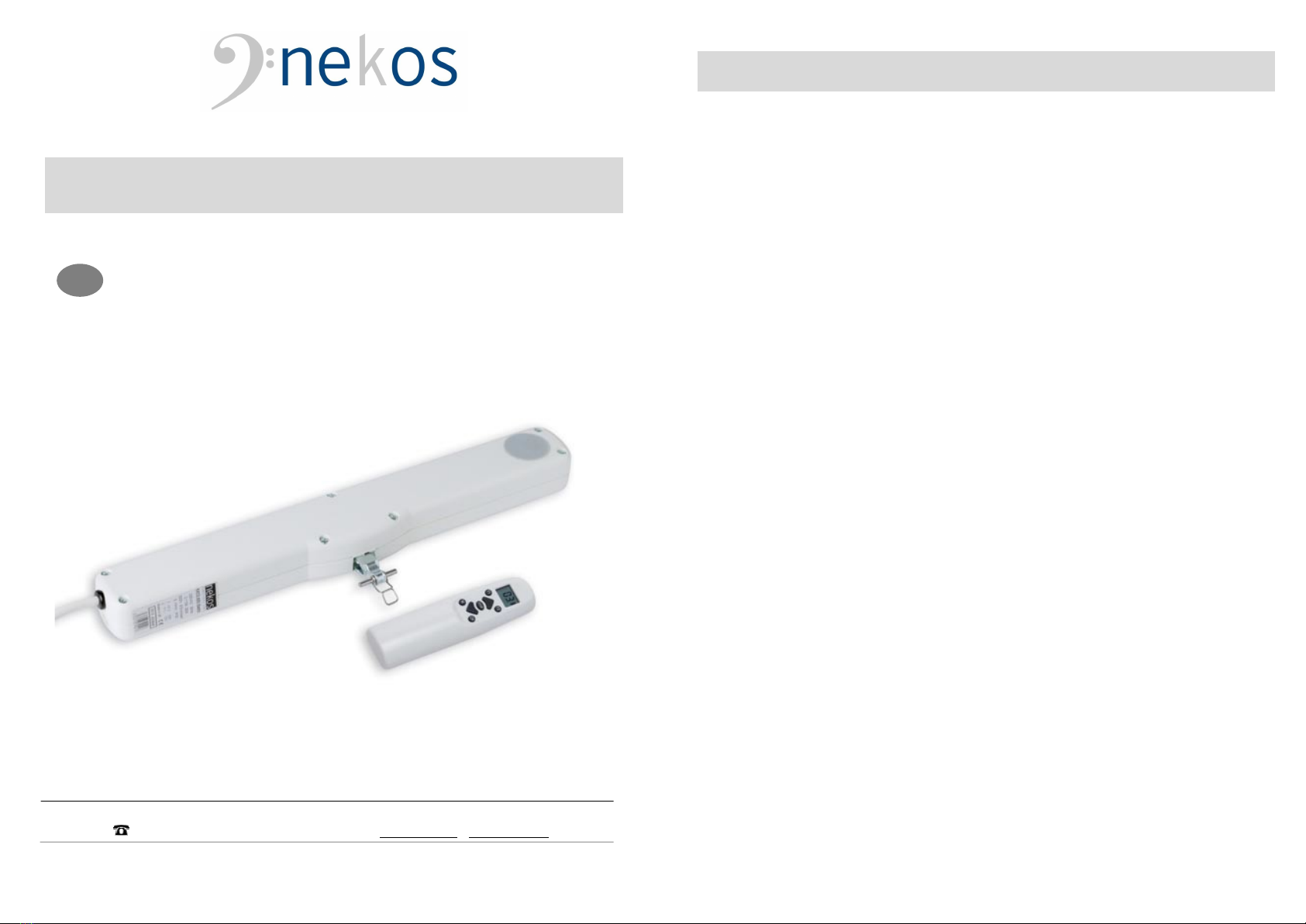
KATO ADV RADIO
INSTRUCTION MANUAL
CHAIN ACTUATOR
Force 300N – Maximum stroke 400 mm
Electrical feeding 110-230V~ 50/60Hz
NEKOS S.r.l. - Via Capitoni, 7/5 - 36064 Colceresa (VI) – ITALY
EN
2
USER INSTRUCTIONS
CAUTION. Carefully observe all the following installation
instructions to ensure personal safety.
The device is not intended for use by persons (including children)
with reduced physical, sensory or mental capabilities, or lacking
experience and knowledge. Do not allow children to play with the
fixed controls and keep any remote-control units out of their reach.
Have installation checks performed periodically by qualified
personnel from a service centre authorised by the manufacturer. Do
not use if repair or adjustment is required.
CAUTION: if the power cable is damaged, it must be replaced by
qualified personnel from a service centre authorised by the
manufacturer.
CAUTION. Disconnect the power supply during cleaning or
maintenance operations. Do not use solvents or jets of water to
wash the appliance; the appliance should not be submerged in
water.
In the event of fault or malfunction, switch off the device at the main
switch. All repairs and adjustments (e.g. setting the stroke) must
only be performed by qualified personnel from a service centre
authorised by the manufacturer.
Always request exclusive use of original spare parts. Failure to
respect this condition could compromise safety and invalidate the
benefits contained in the warranty for the appliance. In the event of
any problems or queries, consult your agent or contact the
manufacturer directly.
The A-weighted sound pressure level is less than 70dB(A).
Carefully preserve these instructions after installation.
3
INSTALLER INSTRUCTIONS
nekos products have been manufactured in accordance with safety standards and
conforms to the stipulations of current standards in force.
When correctly assembled, installed and used according to the present instructions, they
will not generate any danger for persons, animals or items.
Symbols used in the manual
DANGER This indication draw the attention about potential dangers for safety and
health of peoples and animals.
Contents
1. Security rules ................................................................................................................ 4
2. Formulas and recommendations for installation .......................................................... 5
3. Technical information about function ............................................................................ 6
4. Manufacture and reference standards ......................................................................... 6
5. Label data and markings .............................................................................................. 6
6. Technical data .............................................................................................................. 7
7. Electric power supply .................................................................................................... 7
8. Electric power supply and sensor connection ............................................................. 8
9. Electrical connection ..................................................................................................... 8
10. Open and close commands ......................................................................................... 9
11. Rain detection sensor ................................................................................................ 11
12. Predominance of the commands ............................................................................... 11
13. Programming actuator ............................................................................................... 11
14. Assembly ................................................................................................................... 12
15. Meaning of the LED flashing mode ........................................................................... 15
16. Checking for correct assembly .................................................................................. 16
17. Emergency manoeuvres, maintenance and cleaning ............................................... 16
18. Troubleshooting ........................................................................................................ 17
19. Environmental protection ........................................................................................... 17
20. Certificate of guarantee ............................................................................................. 17
21. Declaration of incorporation (for a partly completed machine) and EC Declaration of
Conformity .................................................................................................................. 19
4
1. SECURITY RULES
CAREFULLY OBSERVE ALL THE FOLLOWING INSTALLATION INSTRUCTIONS TO ENSURE
PERSONAL SAFETY. IMPROPER INSTALLATION CAN SERIOUSLY ENDANGER SAFETY.
MANDATORY RISK ANALYSIS AND PROTECTION MEASURES.
The Nekos electrical actuators comply with the Machinery Directive (2006/42/EC), Standard
IEC 60335-2-103 (Particular requirements for drives for gates, doors and windows) and
other directives and regulations indicated in the attached Declarations of Incorporation and
CE Conformity (at the end of the manual). According to the Machinery Directive, actuators
are “partly completed machinery” intended for incorporation into doors and windows. The
manufacturer/supplier of the window is required, with exclusive responsibility, to ensure the
compliance of the entire system with the applicable standards and to issue CE certification.
We strongly discourage any use of the actuators other than that specified and therefore, in
any case, the supplier of the complete system retains full liability.
For systems installed at a height of less than 2.5 m above floor level or other levels
accessible to users, the manufacturer/supplier of the window must conduct risk analysis
regarding potential harm (violent blows, crushing, wounds) caused to people by normal use
or possible malfunction or accidental breakage of the automated windows, and to
implement suitable protective measures in view of these. Such measures include those
recommended by the specified standard:
- controlling the actuators via a “deadman’s button” placed near the system and within
the operator’s field of view, to ensure that people are out of the way during operation.
The button must be placed at a height of 1.5 m and operated by key if accessible to the
public; or:
- use of contact safety systems (also included in the actuators) that ensure a maximum
closing force of 400/150/25 N, measured in accordance with paragraph BB.20.107.2 of
IEC 60335-2-103; or:
- use of non-contact safety systems (lasers, light grids); or:
- use of fixed safety barriers that prevent access to moving parts.
Automated windows are deemed adequately protected if they:
- are installed at a height of >2.5 m; or:
- have a leading-edge opening of <200 mm and a closing speed of <15 mm/s; or:
- are part of a smoke and heat evacuation system for emergency use only.
In any case, moving parts of windows that could fall below 2.5 m following breakage of a
system component need to be fixed or secured in order to prevent them from suddenly
falling or collapsing: e.g. the use of safety arms on bottom-hung windows.
The device is not intended for use by persons (including children) with reduced
physical, sensory or mental capabilities, or lacking experience and knowledge. Do
not allow children to play with the fixed controls and keep any remote-control units
out of their reach.
The actuator is destined exclusively for installation indoors. For any special
application we recommend you consult the manufacturer beforehand.
After removing packaging, check for any damage on the appliance.
Always request exclusive use of original spare parts. Failure to respect this
condition could compromise safety and invalidate the benefits contained in the
warranty for the appliance.
In the event of any problems or queries, consult your agent or contact the
manufacturer directly.
5
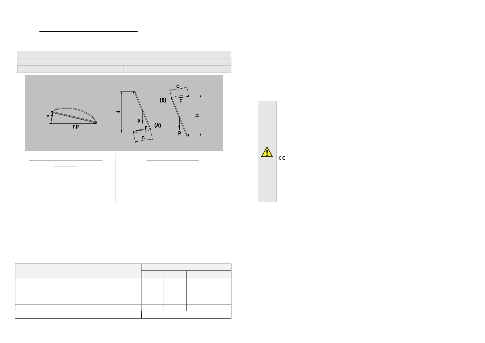
2. FORMULAS AND RECOMMENDATIONS FOR INSTALLATION
2.1. Calculation of opening / closure force
Using the formulas below, approximate calculations can be made for the force required
to open or close the window considering all the factors that determine the calculation.
Symbols used for the calculation
F (Kg) = Force for opening or closing P (Kg) = Weight of the window (mobile sash only)
C (cm) = Opening stroke (actuator stroke) H (cm) = Height of the mobile sash
For horizontal light domes or
skylights
F = 0.54 x P
(Eventual weight of snow or wind on the
cupola should be calculated separately).
For vertical windows
TOP HUNG WINDOWS, OUTWARD OPENING (A)
BOTTOM HUNG WINDOWS (B)
F = 0.54 x P x C : H
(Eventual load of favourable or unfavourable
wind on the sash should be calculated
separately.)
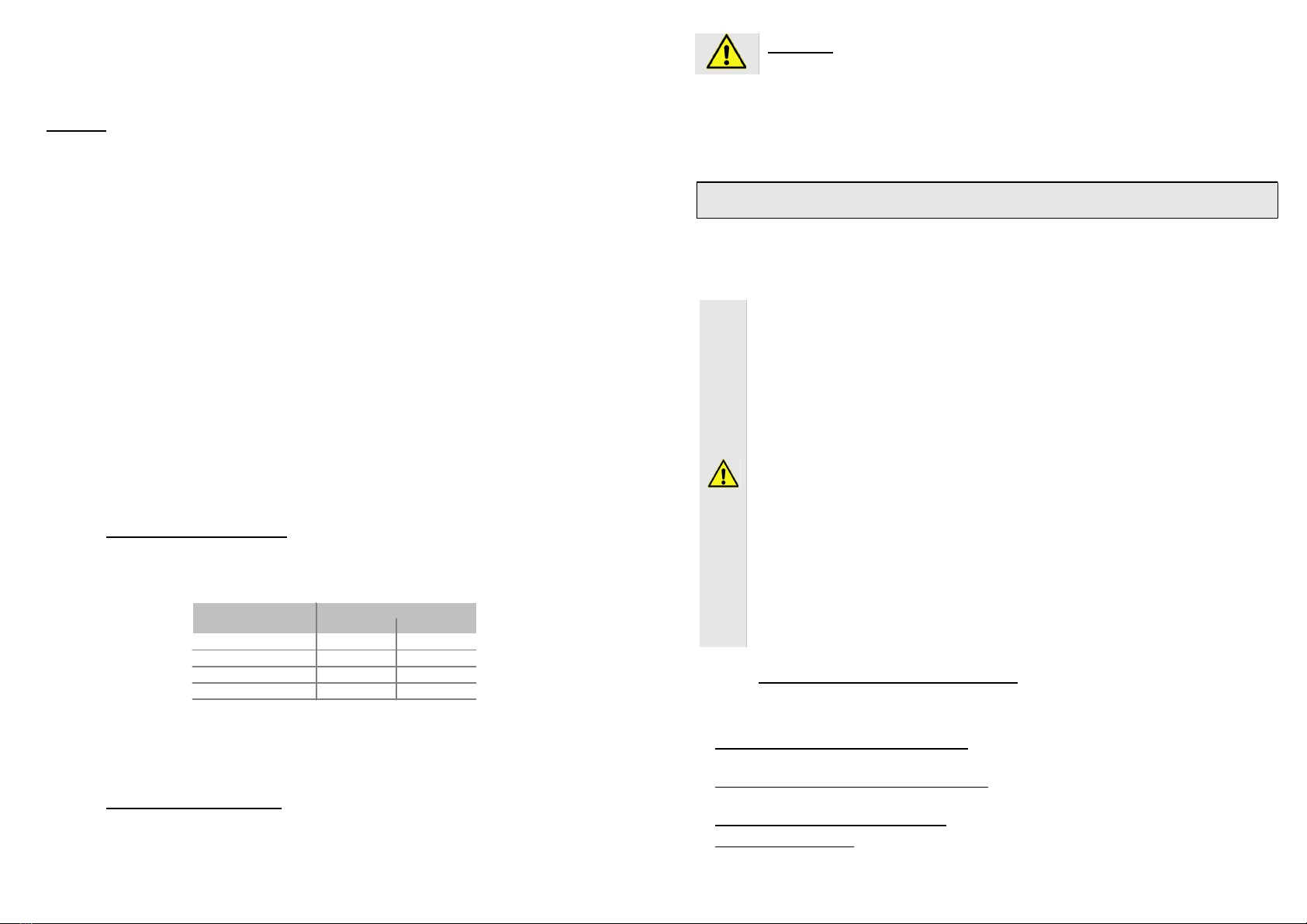
2.2. Maximum opening according to height of sash
The actuator stroke is in accordance with the height of the sash and its application.
Check that the actuator stroke does not touch the profile of the sash and that the chain
does not exert force on the window frame (measurements in mm).
ATTENTION. For safety reasons the actuator should not be assembled if dimensions are
inferior to those indicated in the table below. In the event that the height of the sash should
be lower, call on the manufacturer to check the appliance.
Mode of installation Selection of actuator stroke
110 200 300 400
Light domes, skylights or vertical top hung windows
opening outwards with frontal assembly 150 250 350 450
Top hung windows opening outwards with
horizontal assembly 150 250 350 450
Bottom hung windows (motor on frame) 250 450 600 700
Bottom hung windows (motor on sash) Consult manufacturer
6
3. TECHNICAL INFORMATION ABOUT FUNCTION
The chain operated actuator opens and closes windows by means of a steel chain
located inside the cover. Movement is powered by electricity which powers a gear
motor controlled by an electronic function device. Window opening can be programmed
to open at 110, 200, 300 and 400 mm (see respective chapter).
During closure the end course uses a self-regulating electronic process with power
absorption and therefore requires no regulation.
The actuator leaves the factory with factory settings of +1 cm for the return course
which allows the actuator to be assembled without electricity, with the window in closed
position after assembly is complete.
4. MANUFACTURE AND REFERENCE STANDARDS
INTENDED USE. The KATO ADV RADIO chain actuator is designed and built
to open and close awning and bottom-hung windows, dormer windows, domes
and skylights used for ventilation and climate control in rooms; any other use is
strongly discouraged, with the supplier of the entire system in any case
retaining sole liability. It can also be used in combination with the NRS1
operated rain sensors.
The actuator is manufactured in accordance with the Directives and following
Regulations listed in the attached Declaration of Incorporation and Conformity
.
Electrical connections must conform to regulations in force for the design and
set up of electrical equipment.
To ensure efficient separation from the grid, an approved type of bipolar “dead-
man” switch should be used. An omnipolar general power switch with minimum
distance of 3 mm between contacts should be installed upstream of the control
line.
The KATO ADV RADIO actuator is packed in one single carton.
Each package contains:
Actuator with 2 metre (±5%) lead.
Standard support brackets with distancer (A).
Bracket for vertical assembly of the actuator (B).
Bracket for transom window (C).
Bracket for outward opening fixture (D).
Template for boring.
Instruction manual.
5. LABEL DATA AND MARKINGS
The KATO ADV RADIO actuators have CE marking and comply with the Standards
listed in the Declaration of Conformity. They also come with a Declaration of
Incorporation, due to their classification by the Machinery Directive as “partly completed
machines”. Both declarations are included in the final pages of this manual.

7
The plate data is displayed on an adhesive label placed on the outside of the casing,
which must remain intact and visible.
The main information it displays includes: manufacturer's address, product name -
model number, technical characteristics, production date and serial number.
In the event of a complaint, please indicate the serial number (SN) displayed on the
label. An explanation of the symbols used on the label to abbreviate the technical
characteristics is given in the table in the chapter on “TECHNICAL DATA”.
6. TECHNICAL DATA
MODEL KATO ADV RADIO
Force exerted by thrust and traction (F
N
) 300 N
Strokes (S
V
) 110, 200, 300, 400 mm
Power supply voltage (UN) 110-230V~ 50/60 Hz
Rated absorbed current (I
N
) 0,31 A - 0,24 A
Current consumption with no charge 0,084 A - 0,042 A
Charge absorbed at nominal load (P
N
) 23-27 W
No load speed 15,7 mm/s
No load duration (400 mm) 25 s
Electrical insulation Class II
Type of service (DR) 2 cycles
Working temperature - 5 + 65 ºC
Protection index IP30
Adjustment of socket at casing Autopositioning
Holding nominal force (it can vary according to
the chosen brackets) 1600 N
Connection of two or more devices in parallel YES
Limit switch stop at opening Electronic by means of dip-switches
Limit switch stop at closure At absorption of charge
Dimensions 386,5x59x37
Weight 1,000 kg
Any information reported in this table is not binding and may be susceptible to variations without
notice
7. ELECTRIC POWER SUPPLY
Warning. Check that the electric power supply used corresponds to that
specified on the “technical data” label attached to the machine.
The manufacturer cannot be held liable for damage due to an application which is
incorrect or non-compliant with regulatory requirements.
The actuator is powered by a mains voltage, in alternating current, of 110-230V~ with a
frequency of 50/60 Hz.
The actuator is already equipped with a power supply cable which is 2 meters long. The
cable has two colored conductors: Phase (brown) and Neutral (sky-blue).
The connection between the line and the power supply cable of the actuator must be
protected by a magnetothermic switch between the line and actuator.
8
7.1. Selecting the cross-section of electric power supply cables
The cross-section of the electric power supply conductors must comply with current
standards on electrical systems, without prejudice to standard EN 60335 for connected
electrical devices.
8. ELECTRIC POWER SUPPLY AND SENSOR CONNECTION
8.1. Electric power supply cable
The power supply cable is already wired to the actuator. It is used for the electric
power supply of the system and should be connected to the electricity mains. The
power supply cable has two conductors: sky-blue, brown.
8.2. Cable entry to the terminal block
The cables entering on the left, in the same cable
feedthrough, are the following low-voltage cables:
Rain sensor cable (five conductors).
Manual open/close control cable.
After the wiring is completed (see the “Electrical
connection” chapter) and the cables and cable
feedthrough are arranged properly, it is
recommended that the cable entry be sealed with
a drop of silicone; this will prevent humidity or
water from entering.
9. ELECTRICAL CONNECTION
ELECTRIC SHOCK HAZARD.
Before beginning any work on the machine's wiring, make certain that the
electric power has been disconnected; failure to observe this rule may
compromise safety.
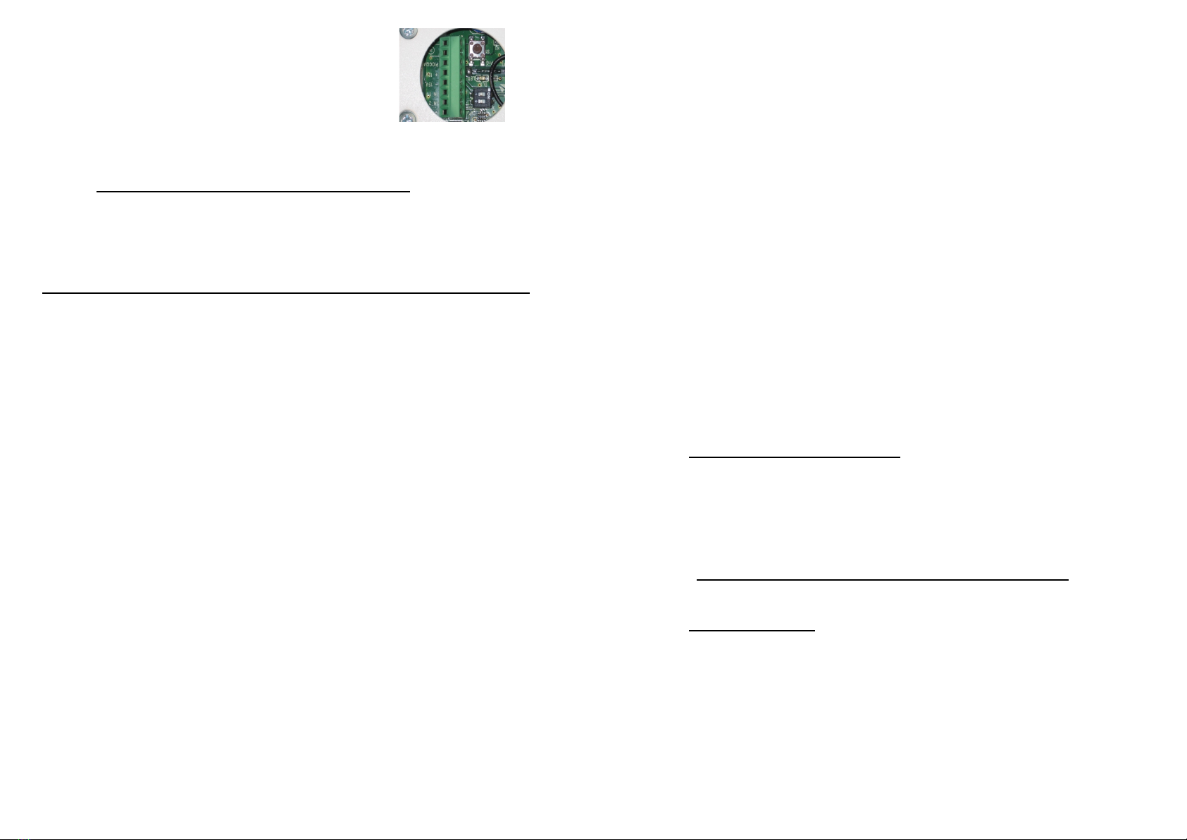
Cable entry to the terminal block
No connection to the symbols indicated to the
side. FUNCTION NOT PRESENT in this
system
Connection of the rain detection sensor, model
NRS1 (five conductors):
Red (+) connected to +15V,
Black (-) connected to -15V,
Blue (N.O. contact) connected to “PIOGGIA”,
Green (common) connected to -15V,
Violet (N.C. contact) not used and should be
electrically isolated.
9
Connection of the manual control with 3
conductors [the common conductor on (COM),
the conductor for opening on (IN 1) and the
conductor for closing on (IN 2)].
10. OPEN AND CLOSE COMMANDS
10.1. Remote electronic control (Radio remote control)
The PIK radio remote control is the standard-equipped device for controlling the KATO
ADV RADIO motor.
For more details on the characteristics and operation of the PIK radio remote control,
consult the instructions manual provided with the radio remote control itself.
Some functions of the radio remote control are not discussed in this manual.
THE TRANSMITTER IS NOT FACTORY-PROGRAMMED.
First follow the radio remote control instructions and then those provided below
concerning the specific operation of the machine you would like to control.
10.1.1. Saving the radio remote control
The radio remote control supplied is the PIK model, with 30 channels and a display,
which transmits at the radio frequency of 433.92 MHz; no other radio remote control
model is provided for the KATO ADV RADIO. Several actuators can be controlled with
a single radio remote control, however each channel must correspond to a KATO ADV
RADIO actuator and thus a window.
The encoding used varies for each channel, so each transmission will send a signal
that is different from all the others. It follows that the receiver must be able to recognize
the enabled transmitters, thus the transmission codes should be saved following the
procedure below:
Equip yourself with the radio remote control, checking beforehand that it is
working, has charged batteries and is in good condition.
Select the desired channel on the radio remote control. (Consult the instructions
manual of the PIK radio remote control).
On the KATO ADV RADIO, briefly press (for about 1 second) the small “PRG”
button located near the terminal block. The slowly flashing LED indicates that it is
waiting to receive a valid radio code.
Within 10 seconds, press any one of the up arrow ▲, STOP or down arrow ▼
buttons two times (once to activate the display of the radio remote control and the
second time to transmit the radio code).
If the code is saved correctly, the LED will emit one long flash (1 sec.) to confirm;
then the LED will go out and remain at rest.
If the code is not saved correctly - due to the memory being full, for example, or
the radio remote control being incompatible - the LED will emit a series of quick
flashes for about 1 second; then the LED will go out and remain at rest.
10
10.1.2. Erasing the radio memory
To completely erase the memory of the radio remote control on the machine, press the
“PRG” button and hold it pressed for about 20 seconds until the LED begins to flash
quickly. At this point you can release the button; the flashing continues until the memory
has been completely erased.
10.1.3. Remotely saving a radio remote control
A new radio remote control can be saved remotely – i.e., without accessing the PRG
button – only if at least one radio remote control has already been saved as described
in point 10.1.1 and you have the radio remote control which is already recognized. To
remotely save a radio remote control, follow the procedure below:
Equip yourself with the PIK radio remote control to be saved and set it on the
desired channel (see the instructions provided with the radio remote control).
Equip yourself with the radio remote control already saved and operating on the
KATO ADV RADIO in question.
On the already saved radio remote control, press the following buttons in sequence:
F1, F2 and then STOP. This sequence “opens” the memory of the KATO ADV
RADIO (in the same way as pressing the PRG button).
Within 10 seconds, press any one of the up arrow ▲, STOP or down arrow ▼
buttons of the (new) radio remote control that you want to program two times (once
to activate the display of the radio remote control and the second time to transmit
the radio code).
10.2. Control with conventional button
If necessary, due to unavailability of the radio remote control or other reason, the
controls can be connected by cable.
The control must have a clean (voltage-fee) single-pole contact, normally open, or a
deadman's button, but not a stable switch. It should be connected to the left terminal
block in the actuator, as indicated in the previous “Electrical connection” chapter.
Warning. The IN1 and IN2 controls prevail over the radio commands.
The manual control prevails over radio remote control.
10.3. Ventilation function
The commands issued by the radio remote control can include a specific function called
“VENTILATION”, which has the purpose of ventilating the room naturally for a specified
time.
To activate this function, press the following buttons in sequence: F1, F2, up arrow ▲.
The window opens and, if no other commands are given, closes again automatically
after 5 minutes. In the case in which the rain sensor, a manual command or radio
command intervened, the ventilation function stops; to restore the function, the
sequence of buttons must be pressed again.
11
11. RAIN DETECTION SENSOR
The rain sensor should be installed outside on the window frame and fixed with a screw
or weather-resistant adhesive system. The device acts only on the commands of the
chain actuator.
Warning. The command coming from the rain sensor prevails over any other
command; if a stable switch is assembled with the manual control and forced opening is
instructed, after having reached the opening stroke-end the window closes again, then
it opens again, then closes again, etc. In order to prevent this problem from arising, do
not assemble a stable control switch.
As described above in Chapter 9 (Electrical connection), a rain sensor model NRS1 can
be connected to the KATO ADV RADIO chain actuator with radio control.
The detector is capacitive sensor equipped with a heater in order to render the
detection area insensitive to the formation of dew, humidity and ice and allow it to dry
quickly after rainfall.
NRS1 is a universal sensor with relay output and voltage-free change-over contact (it
can also be used by other systems), with a heater that operates below +4 °C.
If necessary, the heater can be excluded by a dip-switch. The 5-conductor cable
provided is 5 m long, with a highly weather-resistant PVC sheath which is also non fire-
propagating and resistant to UV radiation.
12. PREDOMINANCE OF THE COMMANDS
The rain sensor intervenes when it rains regardless of the state of the commands, i.e.,
the closing command due to rain, if activated, prevails over any manual command.
13. PROGRAMMING ACTUATOR
13.1. Limit switches at opening
Four (4) positions can be selected for the limit switch of the outgoing chain.
To program, adjust the two dip-switches near left terminal board, as indicated in the
following table.
1
2
110
OFF
OFF
200
ON
OFF
300
OFF
ON
400
ON
ON
Limit switch at:
(mm)
Dip-switch n°
After the limit switches have been programmed, run a few check manoeuvres. In the
event of error, programming can be repeated to give the desired track run.
The actuator comes from production set on longer stroke (400 mm), dip-switch 1 in ON;
dip-switch 2 in ON.
13.2. Limit switches at closure
The limit switch at closure is automatic, electronically operated and cannot be
programmed. The actuator stops when the charge is absorbed when the window is
completely closed and the weather stripping is completely depressed.
12
Attention. The actuator at maximum charge, exercises a force enough to
crush fingers in the event of distraction.
After each closure or intervention of the electrical protection mechanism, the chain
moves in the opposite direction for around 1,0/1,5 mm. This is to loosen the tension of
the mechanical parts and gives correct pressure to the weather stripping.
14. ASSEMBLY
These indications are intended for the attention of technicians and specialized
personnel. Basic job and safety techniques are therefore not included.
All preparatory operations, assembly and electrical connections must be carried out by
technical and specialized personnel to guarantee best performances and good function
of the KATO ADV RADIO chain operated actuator.
First of all, please check that the following fundamental points have been satisfied:
Before installing the actuator, check that the moving parts of the window on which it
is to be installed are in perfect working condition and that they open and close
properly and are well balanced (where applicable).
Check that the electrical supply used corresponds to the indications on the
“TECHNICAL DATA” label attached to the machine and that the given temperature
range is compatible with the place of installation.
Actuator specifications must be sufficient for movement of the window without
encountering any obstacle. The limits indicated in the technical data table must not
be superseded (page 7) and the most appropriate stroke should be selected.
Calculations should be checked using the formula indicated on page 5.
Ensure that the actuator has not been damaged during transport, first visually and
then by powering in both directions.
Check that the width of the inside of the window (where the actuator is to be
assembled) is over 405 mm, otherwise the actuator should not be installed.
Check that once the actuator has been installed the distance between the fixed
part of the window frame (where the actuator is to be assembled) and the mobile
part of the window frame (where the bracket is to be fixed) is greater than or
equal to 0 mm. If this is not the case the actuator will not function correctly as the
window will not close correctly. If required, add additional thickness below the
support brackets to reset the quota.
14.1. Preparation of actuator for assembly
Before starting assembly of the actuator, prepare the following material for completion,
equipment and tools.
For fixing onto metal window frames: M5 threaded inserts (6 pieces), M5x12 flat
headed metric screws (6 pieces).
For fixing onto wooden window frames: self-threading screws for wood Ø4.5 (6
pieces).
For fixing onto PVC window frames: self-threading screws for metal Ø4.8 (6 pieces).
Equipment and tools: measuring tape, pencil, drill/screwdriver, set of drill heads for
metal, insert for screwing in, electricians pliers, screwdrivers.

13
14.2. Assembly with outward opening window
Aside the drawing of specific application using
accessories provided. For different mountings,
please contact manufacturer.
A. Pencil in an “X” over the centre line of the window
frame (Fig. 2).
B. Select the correct form of brackets (Fig. 3).
C. Attach the template to the window frame (fixed part)
and line axis up with the centre line “X” traced earlier
(Fig. 4). Warning: for window frames not on the same
plane, cut the part of the template coloured in grey and
fix this to the moveable part of the window frame,
taking care to keep it in the same position.
D. Bore holes in the window frame at the points indicated
on the template (Fig. 5).
E. Assemble the two brackets with the distancer (to help
position correctly. Once it has served its purpose it can
be removed). Mount the supports onto the frame with
the appropriate screws provided. Check that
everything is aligned both horizontally and vertically.
F. Mount the bracket for outward opening windows onto
the moveable part of the frame in accordance with the
markings indicated on the template.
G. Complete assembly of the chain terminal with the
safety clip inserted onto the pin Ø4x32 (provided) in
median position (see fig. 6).
H. Mount the actuator onto the brackets by inserting the
two openings at each side onto the corresponding pins
on the brackets.
I. Rotate the actuator 90°, bring the chain terminal up to
the bracket and insert the pin into the opening on the
bracket. Insert the safety clip into the bracket.
J. Check that the exit on the chain is perfectly aligned
with the bracket. If the chain is not aligned with the
bracket, loosen the fixing screws and reposition the
bracket correctly.
K. Check all electrical connections with the diagram on
the label attached to the lead and and in conformity to
indications on chapter 9 – Electrical connection.
L. Carry out a complete check of opening and closure of
the window. Once the closure phase has been
completed, check that the window frame is completely
closed by checking the pressure on the weather strips.
Outward application
Figure 2
Figure 3
Figure 4
Figure 5
Figure 6
14
14.3. Assembly on transom window
Aside the drawing of specific application using
accessories provided. For different mountings, please
contact manufacturer.
Before starting, check that there are at least two
mechanical compass safety stops or other form of
stops connected to the frame, and ensure that the
stops can prevent any accidental fall of the window. Your
safety is at hand.
A. Pencil in an “X” over the centre line of the window
frame (Fig. 7).
B. Select the correct form of brackets (Fig. 8).
C. Attach the template to the window frame (fixed part)
and line axis up with the centre line “X” traced earlier
(Fig. 9). Warning: for window frames not on the same
plane, cut the part of the template coloured in grey and
fix this to the moveable part of the window frame,
taking care to keep it in the same position.
D. Bore holes in the window frame at the points indicated
on the template (Fig. 10).
E. Assemble the two brackets with the distancer (to help
position correctly. Once it has served its purpose it can
be removed). Mount the supports onto the frame with
the appropriate screws provided. Check that
everything is aligned both horizontally and vertically.
F. Mount the bracket for outward opening windows onto
the moveable part of the frame in accordance with the
markings indicated on the template.
G. Complete assembly of the chain terminal with the
safety clip inserted onto the provided pin Ø4x32 in
median position (see fig. 11).
H. Mount the actuator onto the brackets by inserting the
two openings at each side onto the corresponding pins
on the brackets.
I. Rotate the actuator 90°, bring the chain terminal up to
the bracket and insert the pin into the opening on the
bracket. Insert the safety clip into the bracket.
J. Check that the exit on the chain is perfectly aligned
with the bracket. If the chain is not aligned with the
bracket, loosen the fixing screws and reposition the
bracket correctly.
K. Check all electrical connections with the diagram on
the label attached to the lead and in conformity to
indications on chapter 9 – Electrical connection.
L. Carry out a complete check of opening and closure of
the window. Once the closure phase has been
completed, check that the window frame is completely
closed by checking the pressure on the weather strips.
Inward application–transom window
Figure 7
Figure 8
Figure 9
Figure 10
Figure 11

15
14.4. Assembly of actuator onto bay or outward opening window
Aside the drawing of specific application using
accessories provided. For different mountings, please
contact manufacturer.
A. Pencil in an “X” over the centre line of the window
frame (fig. 12).
B. Select the correct form of brackets (fig. 13).
C. Fold the template along the green dotted line and keep
in position at 90°. Attach one part to the window frame
(fixed part), taking care to line up the axis with the “X”
previously pencilled in on the central line and line the
folded part up against the moveable part of the frame.
Warning: as various different applications are
possible, place the actuator in a central position and
adjust the positions of the brackets, taking care to
keep the actuator aligned with the window section.
D. Bore holes into the window frame at the points
indicated (fig. 14).
E. Mount the bracket for outward opening windows onto
the moveable part of the frame in accordance with the
markings indicated on the template.
F. Complete assembly of the chain terminal with the
safety clip inserted onto the provided pin Ø4x32 in
median position (see fig. 15).
G. Mount the two brackets on to the sides of the actuator.
H. Position the actuator onto the window frame and line
up with the holes bored earlier. Fix the actuator.
I. Bring the chain terminal up to the bracket and insert
the pin into the hole on the bracket. Attach the safety
clip to the bracket.
J. Check that the exit of the chain is perfectly aligned with
the bracket. If the chain is not aligned, loosen the fixing
screws and reposition the bracket correctly.
K. Check all electrical connections with the diagram on
the label attached to the lead and in conformity to
indications on chapter 9 – Electrical connection.
L. Carry out a complete check of opening and closure of
the window. Once the closure phase has been
completed, check that the window frame is completely
closed by checking the pressure on the weather strips.
Vertical assembly on outward
opening
Figure 12
Figure 13
Figure 14
Figure 15
15. MEANING OF THE LED FLASHING MODE
The LED can be seen on the electronic board after removing the closure plug. In some
cases it flashes in different ways depending on the signal it is emitting; the different
flashing modes indicate the precise behavior of the actuator during the programming of
the machine, radio remote control or rain sensor.
16
The table below summarizes the meaning of the LED flashing mode.
Ref.
Flashing Flashing
frequency Meaning
1 Off Actuator at rest, no alarm is active
2 Steady-on Function not provided for
3 Slow flashing for
10 seconds 1 per second The machine is waiting to receive a valid
radio remote control code.
4 On for
2 seconds Steady-on The machine has saved the radio
remote control correctly
5 Flashing for
2 seconds 2 per second The machine has not saved the radio
remote control
6 Fast continuous
flashing 2 per second Rain sensor active
7 Flashing for 5
seconds 2 per second Erasing the radio remote control
memory
16. CHECKING FOR CORRECT ASSEMBLY
Check that the window has closed completely, even at the corners, and check there
are no obstacles caused by assembly in the wrong position.
Check that when the window frame is closed, the chain terminal is at least a couple
of millimetres distant from the actuator body. This will ensure correct closure of the
window with correct pressure on the weather stripping. If the chain terminal is not
positioned as stated there is no guarantee the window will close correctly.
Check that all attachments and support brackets are tightly fixed to the window
frame and that all screws are correctly tightened.
Check that the window moves to the desired position in accordance with the limit
switch selected.
Check that the gear motor support brackets are aligned and the four fixing screws
are firmly screwed into position.
17. EMERGENCY MANOEUVRES, MAINTENANCE AND CLEANING
Should the window have to be opened manually in the event of no electricity,
mechanical failure, or for normal maintenance or cleaning of the external surface of the
window frame, the following instructions should be followed:
1. Release the safety clip locking the chain terminal to the bracket.
2. Hold the window with one hand and pull the pin out of
the opening with the other hand (Fig. 16).
3. Manually open the window frame.
ATTENTION: DANGER – the window could fall as the
sash is no longer held in position by the chain.
4. After maintenance and/or cleaning repeat points 1 and 2
in reverse order.
Figure 16

17
18. TROUBLESHOOTING
Please consult the following table for any eventual problems with function during
installation or normal use:
Problem Possible cause Solution
Actuator doesn’t
work
No electricity supply for feeder.
Connecting cable not
connected or wire not
connected.
Winder on the transformer is
broken.
Check state of safety switch.
Check all electrical
connections of gear motor.
Replace the electronics card
of the feeder.
LED is lit but
actuator doesn’t
work.
Gear motor is damaged due to
a shock. Motor connection has
unsoldered or has been
disconnected.
Send actuator to a Service
Centre.
Although selection
has been carried
out correctly the
gearmotor will not
take a limit switch.
Programming hasn’t been
carried out correctly.
Irregular function or break in
the electrical contact for the
dip-switch.
Repeat programming for dip-
switch.
Send actuator to a Service
Centre.
Actuator does not
move.
The radio command has not
been accepted by the radio
receiver.
Repeat the memorisation
procedure for the radio
command.
Rain sensor does
not close window.
The sensor is not a NRS1
model.
Sensor if faulty.
Replace the sensor with a
proper model.
Send sensor to a Service
Centre.
19. ENVIRONMENTAL PROTECTION
All materials used in the manufacture of this appliance are recyclable.
We recommend that the device itself, and any accessories, packaging, etc. be sent to a
centre for ecological recycling as established from laws in force on recycling. The
device is mainly made from the following materials: aluminium, zinc, iron, plastic of
various type, cuprum.
Dispose materials in conformity with local regulations about removal.
20. CERTIFICATE OF GUARANTEE
The manufacturer will guarantee good function of the appliance. The manufacturer shall
undertake to replace defective parts due to poor quality materials or manufacturing
defects in accordance with article 1490 of the Civil Code.
The guarantee covers products and individual parts for 2 years from the date of
purchase. The latter is valid as long as the purchaser possesses proof of purchase and
completion of all agreed conditions of payment.
Guarantee of good function of appliances agreed by the manufacturer implies that the
latter undertakes to repair or replace free of charge and in the shortest period possible
any parts that break while under warranty.
18
The purchaser is not entitled to any reimbursement for eventual direct or indirect
damage or other expenses incurred. Attempt to repair by personnel unauthorised by the
manufacture shall render the warranty null and invalid.
The warranty does not cover fragile parts or parts subject to natural wear and tear or
corrosion, overload, however temporary etc. The manufacturer will accept no
responsibility for eventual damage incurred by erroneous assembly, manoeuvre or
insertion, excessive stress or inexpert use.
Repairs performed under guarantee are always "ex factory of the manufacturer".
Respective transport expenses (out/back) are the responsibility of the purchaser.

19
21. DICHIARAZIONE DI INCORPORAZIONE (per una quasi macchina) E
DICHIARAZIONE CE DI CONFORMITÀ / Declaration of Incorporation (for a
partly completed machine) and EC Declaration of Conformity
Con la presente il / Hereby the
Costruttore:
Manufacturer:
Nekos Srl
Via Capitoni 7/5- 36064 Colceresa (Vicenza) - Italy
Tel +39 0424 411011 – Email info@nekos.it
dichiara sotto la propria responsabilità che i seguenti prodotti:
declare under its own responsibility that the following products:
Descrizione prodotto :
Product Designation:
Attuatore a catena per finestre
Window chain drive
Modello / Type : 230 V : KATO ADV RADIO
Anno di costruzione dal / Year of manufacturing from: 2017
Soddisfa gli applicabili requisiti essenziali della
Direttiva Macchine 2006/42/EC, Allegato I
Fulfil the essential requirements of the Machinery Directive 2006/42/EC, Annex I, Art. 1.1.2, 1.1.3, 1.1.5, 1.2.1,
1.2.2, 1.2.3, 1.2.4.1, 1.2.6; 1.3.2, 1.3.4, 1.3.9, 1.5.1, 1.5.2, 1.5.6, 1.5.7, 1.5.8, 1.5.9, 1.5.10, 1.5.11, 1.7.1, 1.7.1.1,
1.7.3, 1.7.4.2, 1.7.4.3
La documentazione tecnica pertinente è compilata secondo l’Allegato VII, sezione B
The relevant technical documentation is compiled in accordance with Annex VII, Part B
La persona autorizzata a costituire la documentazione tecnica pertinente è:
The person authorised to compile the relevant technical documentation is: Giuliano Galliazzo – Nekos S.r.l.
Su richiesta adeguatamente motivata delle autorità nazionali, la documentazione tecnica dei citati prodotti sarà resa
disponibile, via e-mail, entro un tempo compatibile con la sua importanza.
In response to a reasoned request by the national authorities, we will provide, via e-mail, the relevant information on
the product listed above within an adequate period proportional to its importance.
Inoltre i succitati prodotti sono conformi alle disposizioni pertinenti delle seguenti Direttive:
Furthermore the products listed above complies with the provisions of followings Directives :
2014/53/EU Direttiva Apparati Radio / Radio Equipment Directive (RED)
2011/65/EU Direttiva sulla restrizione dell’uso di determinate sostanze pericolose nelle apparecchiature
elettriche ed elettroniche (Direttiva RoHS) / Restriction of the use of certain hazardous substances Directive
(RoHS Directive)
2015/863/EU Direttiva Delegata recante modifica dell’allegato II della Direttiva 2011/65/EU del
Parlamento Europeo e del Consiglio per quanto riguarda l’elenco delle sostanze con restrizioni d’uso /
Delegated Directive amending Annex II of Directive 2011/65/EU of the European Parliament and of the Council
regarding the list of substances with usage restrictions
e delle seguenti norme armonizzate e/o specifiche tecniche:
And of the following harmonised standards and/or technical specifications:
ETSI EN 300 220-1 V3.1.1 – ETSI EN 300 220-2 V3.2.1; ETSI EN 301 489-1 V2.2.3 – ETSI EN 301 489-3 V2.1.1
EN 60335-2-103 ; EN 61000-6-3:2007 + A1:2011 + AC:2012; EN IEC 61000-6-2:2019
EN 60335-1:2012 + AC:2014 + A11:2014; EN 50581:2012
La messa in moto di una macchina completa che includa la quasi macchina sopra menzionata, da noi fornita, non è
permessa finché non sia accertato che l’installazione sia stata fatta secondo le specifiche e le indicazioni di
installazione contenute nel “Manuale d’istruzioni” fornito con la quasi-macchina, e che sia stata espletata e
documentata, in apposito protocollo, una procedura di accettazione da parte di un tecnico abilitato.
Commissioning of the complete machinery including the above mentioned drives delivered by us is not allowed until it
is ascertained that the installation of the complete machinery was performed in accordance with the specifications and
the operating and installation advice given in our Mounting Instructions, and that the acceptance procedure was duly
carried out and documented in an acceptance protocol by a specialist.
Questa dichiarazione è fatta dal costruttore / This is declared by the manufacturer :
NEKOS SRL - Via Capitoni 7/5 - 36064 Colceresa (Vicenza) - Italy
Rappresentato da / Represented by :
Giuliano Galliazzo – A.D. Presidente / President CEO Firma / Valid signature
Luogo e data / Place and date : Colceresa 22/09/2021
20
NEKOS S.r.l. - Via Capitoni, 7/5
36064 Colceresa (VI) – ITALY
+39 0424 411011 – +39 0424 411013
www.nekos.it [email protected]
Table of contents
Other nekos Controllers manuals

nekos
nekos KIMO User manual

nekos
nekos SKY 450 Quick start guide

nekos
nekos SKYRO 850 User manual

nekos
nekos ROCK 230 V User manual

nekos
nekos SKY 450 User manual

nekos
nekos KIMO 202 User manual

nekos
nekos KATO 253 Reference manual

nekos
nekos KATO 253 User manual

nekos
nekos SKY 650 User manual

nekos
nekos KATO RADIO 230V User manual


Popular Controllers manuals by other brands

SEW-Eurodrive
SEW-Eurodrive MOVIPRO PHC11A-M1-2A-A1 Series operating instructions

Allo RemoteControl
Allo RemoteControl CHAMBERLAIN TXR4UNI instructions

Mold-Masters
Mold-Masters E-Multi EM1 user manual

Kikkoman Biochemifa
Kikkoman Biochemifa Smart Operation manual

Lovato
Lovato ADX Series Protocol manual

CSI
CSI MR-AHU Installation sheet


