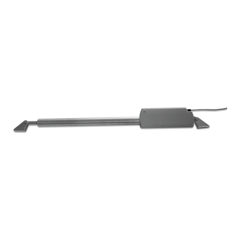
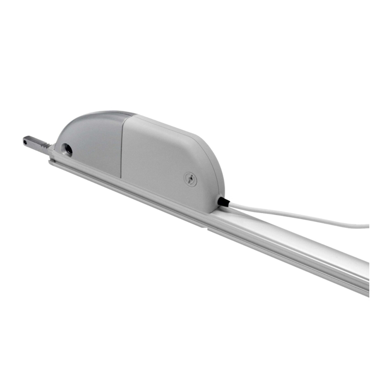
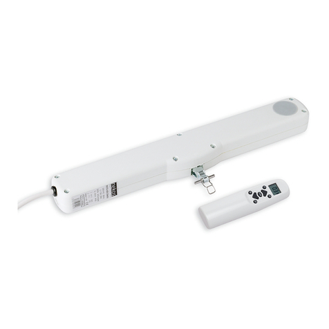
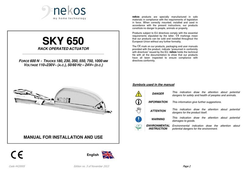
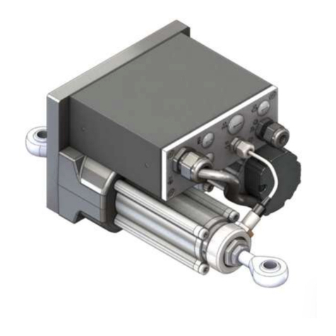
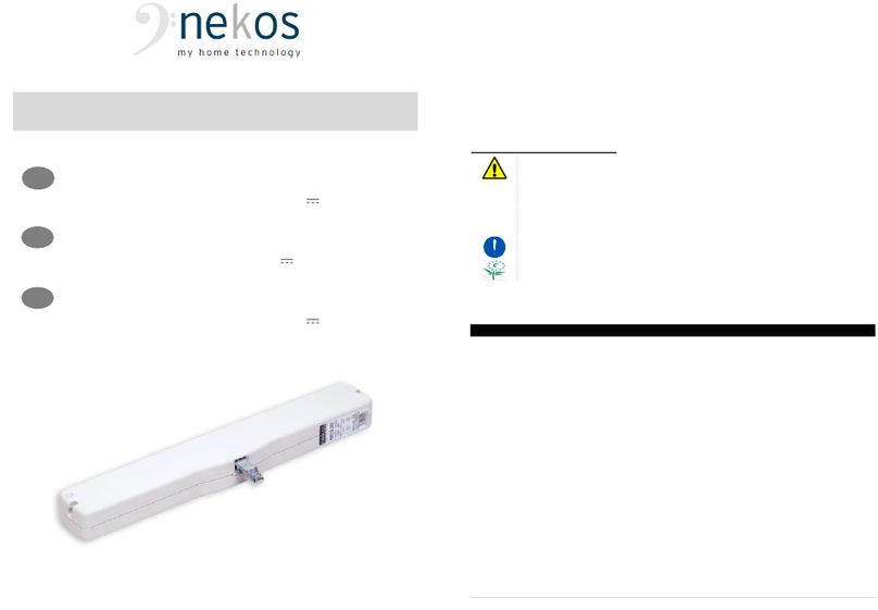
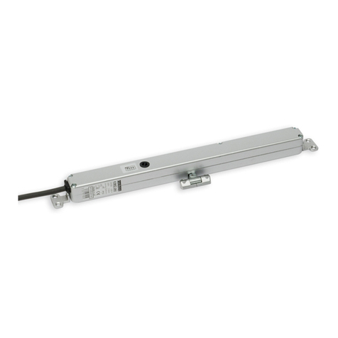
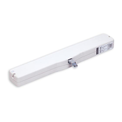
nekos KATO RADIO 230V User manual

Code 4420026Edition no. 1 of1stMarch 2006Printed on 13/07/2006Page 1
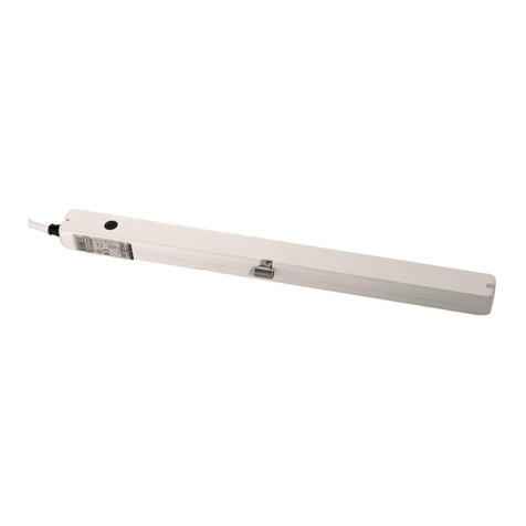
CHAIN OPERATED ACTUATOR____ KATO RADIO
TORQUE300 N-TRUCK 400 MM
ELECTRICAL FEEDING230V~ 50HZ
INSTRUCTION MANUAL
ENGLISH

Code 4420026Edition no. 1 of1stMarch 2006Printed on 13/07/2006Page 2
nekosproducts are specially manufactured in
safe materials in compliance with the
requirementsof legislation in force.When
correctly mounted, installed and used in
accordance with the present instructions, our
products constitute no danger to people, animals
or property.
Products subject to EU directives comply with the
essential requirements stipulated by the latter.
markings mean that our products can be sold and
installed throughout the European Union without
any further formality.
The mark on our products, packaging and
user manuals provided with the product, indicate
“presumed in conformity with directives” issued by
the EU.nekosholds the technical file with all the
documentation to show that our products have all
been inspected to ensure compliance with
directives conformity.

Code 4420026Edition no. 1 of1stMarch 2006Printed on 13/07/2006Page 3
CONTENTS
SAFETY INDICATIONS................................ ................................ ........................... 4
MANUFACTURE AND REFERENCE STANDARDS................................ .......................... 5
ACCESSORIES................................ ................................ ................................ .... 5
TECHNICAL DATA ................................ ................................ ............................... 6
LABEL DATA AND MARKINGS................................ ................................ .................. 6
ELECTRICAL SUPPLY................................ ................................ ........................... 6
REMOTE CONTROL DEVICES (RADIO OPERATED REMOTECONTROL AND RAIN SENSOR)... 7
oMEMORISING RADIO COMMANDS; ACTUATOR DIP-SWITCHES ACCESSIBLE................ 7
oMEMORISING ANOTHER RADIO CONTROL DEVICE; DIP-SWITCH NOT ACCESSIBLE...... 7
oMEMORISING COMMANDS FOR THE RADIO OPERATED P2/R RAIN SENSOR............... 8
PROGRAMMING THE LIMITSWITCHES ................................ ................................ ...... 8
oLIMIT SWITCHES AT OPE NING................................ ................................ ........... 9
oLIMIT SWITCHES AT CLOSURE................................ ................................ .......... 9
TECHNICAL INFORMATION ABOUT FUNCTION................................ ............................ 9
ASSEMBLY................................ ................................ ................................ ......... 10
oASSEMBLY WITH OUTWARD OPENING WINDOW................................ .................... 11
oASSEMBLY ON TRANSOM WINDOW................................ ................................ .... 12
oASSEMBLY OF ACTUATOR ONTO BAY OR OUTWARD OPENING WINDOW..................... 13
ELECTRICAL CONNECTIONS................................ ................................ .................. 14
LUMINOUS INDICATIONS ON LED................................ ................................ ........... 15
CHECKING FOR CORRECT ASSEMBLY................................ ................................ ...... 15
EMERGENCY MANOEUVRES, MAINTENANCE AND CLEANING................................ ........ 15
TROUBLESHOOTING................................ ................................ ............................ 16
ENVIRONMENTAL PROTECTION................................ ................................ ............... 17
WARRANTY................................ ................................ ................................ ........ 17
PRESSURE CALCULATION FORMULAS................................ ................................ ..... 18
DECLARATION OFCONFORMITY................................ ................................ ............. 19

Code 4420026Edition no. 1 of1stMarch 2006Printed on 13/07/2006Page 4
SAFETY INDICATIONS
ATTENTION: PLEASE READ THE FOLLOWING SAFETY INDICATIONS
CAREFULLY BEFORE ATTEMPTING INSTALLATION OF THIS APPLIANCE.
THESE INDICATIONS WILL HELP TO AVOID CONTACT WITH ELECTRICAL
CURRENT, INJURY AND OTHER ACCIDENTS. PLEASE KEEP THIS MANUAL
FOR FUTURE CONSULTATION.
The KATORADIOchain operated actuator has been designed exclusively for
moving windows. Any use of the actuator for applications other than those
indicated must previously be authorized by the manufacturer upon technical
verification of the application.
Carefully observe the followings safety indications.
■The device must only be installed by competent and qualified technical staff.
■After removing all packaging, please verify that all parts of the appliance are
present.
■Any plastic bags, polystyrene, or small metallic parts such asnails, clips, etc.
must be stored out of the reach of children as they constitute potential sources
of danger.
■Before connecting the appliance to the electricity supply, check that the
electricity supply in use has the same characteristics as those indicated on the
technical data label on the device.
■This appliance is destined exclusively for the use for which it has been
designed and the manufacture cannot be held responsible for any damages
incurred by improper use.
■The chain operated actuator has been designed for the exclusive purpose of
internal installation. The manufacturer must be consulted for any other
application.
■Installation of the device must be carried out in accordance with the
instructions set out by the manufacturer. Failure to follow th ese instructions
could compromise safety.
■Electricity supply installation must be carried out in accordance with
regulations in force.
■To ensure effective separation from the electricity grid, we suggest installation
of a temporary approved type bipolar switch (push button). A multi-pole main
switch with minimum contact opening of 3 mm should be installed at the start
of the command line.
■Never clean the device with solvents or jets of water. Never immerse
appliance in water.
■Eventual repairs must only be carried out by qualified staff at a service centre
authorized by the manufacturer.
■Always require exclusive use of original spare parts. Failure to comply with
this stipulation could compromise safety and forfeit warranty benefits for the
device.
■In the event of trouble or doubts, please refer to your trust retailer or directly to
producer.

Code 4420026Edition no. 1 of1stMarch 2006Printed on 13/07/2006Page 5
WARNING
Risk of injury in the event that the window should fall on outward opening
window frames. A safety system should be mounted onto the window to
guard againstfalls. This system should be able to withstand at least three
times the total weight of the window.
This device may cause injury by crushing or dragging. During function, when
the actuator closes the frame, it applies a pressure force of 300N againstthe
ledge of the casing, and all due measures, care and attention should be
taken to avoid any crushing of fingers.
Check that limit switch selection is less than at least one centimetre with
respect to the mechanical stops, limit switches or any eventual obstacles
preventing opening of the wing
In the event of damage or malfunction, switch off the device, disconnect any
electrical connections and request the intervention of a qualified technician .
MANUFACTURE AND REFERENCE STANDARDS
xThe KATO RADIOchain operated actuator has been designed and produced
to open and close bay or outward opening windows, hopper frame windows,
dormer windows, cupolasand skylights. It has been specifically designed for
providing ventilation and air circulation of are as and can also be used in
combination with the P2/Rradio operated rain sensor. It is firmly
recommended the actuator not be used for any other purpose without
previously obtaining authorisation from the manufacturers.
xElectrical connections must conformto regulations in force for the design and
set up of electrical equipment.
xThe actuator has been manufactured in accordance with European Union
directives and has been certified in conformity with marking.
xAny eventual service a nd control device for the actuator must be manufactured
in accordance with regulations in force and must conform to respective
European Community regulation.
ACCESSORIES
The KATO RADIO actuator is packed in one single carton. Each package
contains:
xActuator with 2 metre (±5%) lead.
xStandard support brackets with distancer (A).
xBracket for vertical assembly of the actuator (B).
xBracket for transom window (C).
xBracket for outward opening fixture(D).
xAdhesive template for boring.
xInstruction manual.

Code 4420026Edition no. 1 of1stMarch 2006Printed on 13/07/2006Page 6
TECHNICALDATA
MODEL
KATO RADIO 230V
Pressure torque
300 N
Traction torque
300 N
Track runs (can be selected at any time)
100, 200, 300, 400 mm
Voltage
230V~ 50 Hz
Current consumption at nominal charge
0,115 A
Charge absorbed at nominal load
~ 28 W
No load speed
10 mm/s
No load duration (400 mm)
40 s
Double electrical insulation
YES
Type of service
S2of3 min
Working temperature
-5 + 65 ºC
Protection index
IP30
Adjustment of socket at casing
Autopositioning
Connection of two or more devices in parallel
YES
Limit switch stop at opening
Electronic
Limit switch stop at closure
At absorption of charge
Dimensions
386,5x59x37
Weight
0,970 Kg
Any information reported in this table is not binding and may be susceptible to
variations without notice
LABEL DATA AND MARKINGS
The actuators have been assigned marking and can be
sold onto the market and used throughout European Union
territory without further requirement.
The marking on the product, packaging and user warnings
indicate “presumed conformity to directives” issued by the
EEC.
The manufacturer holds technical archives with
documentation to prove that products have been examined to
assess conformity to directives.
Rating plate data is located on an adhesive polyethylene label
on the outside of the container, printed in blue on a grey
background. All data conform to stipulations required by
community standards in force.
ELECTRICITY SUPPLY
The only electrical connection on the actuator is for conne ction to the electricity
supply at 230V~ 50Hz (AC) by connecting the two wires (L(phase) N(neutral)) on

Code 4420026Edition no. 1 of1stMarch 2006Printed on 13/07/2006Page 7
the feeder cable. The commands for OPENand CLOSE are controlled by electrically
connected radio operated remote control device on 433.92 MHz.
REMOTE CONTROL DEVICES (Radio operated remote control and Rain
sensor)
The radio operated remote control device is the only device used for manually
controlling the actuator. The KATO RADIO model has been designed without any
switch or button commands.
The BLU’Rradio operated remote control has four command buttons, 433.92MHz
transmitter, rolling code, 16 billion billion combinations. Transmitter cloning is
impossible as the code changes at each transmission according to an algorithm which
masks the code.
As the codes used are rolling, each transmitter will transmit a different signal. The
receiver must therefore be able to recognise the transmitters enabled .
Each key on the radio operated remote control corresponds to a motor control
which will be memorised by the operator (see following paragraphs).
Another remote control electronic command device is the radio operated P2/Rrain
sensor (For installation of the P2/Rrain sensor, see the “installation and use
manual”provided in the box of the sensor packaging ).
WARNING. THE ONLY RAIN SENSORWHICH CAN BE USED IS THE RADIO OPERATEDP2/R –OTHER
MODELS WILL NOT FUNCTION. THE SUPPLY CABLE HAS ONLY 2 WIRES CONNECTED (WHITE (+),
YELLOW (-)
The two devices (radio operated remote control and rain sensor) cannot be
programmed at the same time.
The receiver can memorise up to 8transmitters. Any number of transmitters over
and above this will not be accepted.
Memorising radio commands; actuator dip-switches accessible.
WARNING: NEVER ASSIGN THE SAME KEY TO MORE THAN ONE ACTUATOR
1.Set dip-switch n° 1to ON. The red led pilot light will turn on. Set the dip-
switch immediately to OFF.
2.Press the key to be assigned to the actuator until the led pilot light starts to
flash.
3.The led pilot light will stop flashing.
4.Programming is complete, all commands are ready or ready for normal
function.
Memorising another radio control device; dip-switch NOT accessible.
1.Press buttons 1, 2, and 4 on the radio control device for
around 1 second, then press the key to command the
actuator.
2.The red pilot light on the actuator will come on.

Code 4420026Edition no. 1 of1stMarch 2006Printed on 13/07/2006Page 8
3.Press the button on the new radio control device to be
assigned to the actuator. The activator pilot light will start
to flash as soon as the key is released.
4.The pilot light should stop flashing.
5.Programming isnow complete. All commands are ready for normal function.
Memorising commands for the radio operated P2/R rain sensor
The P2/Rrain sensor commands all memorised motors within 60m out in the open
area (walls, metal panels, iron cages etc all drasticallyreduce capacity).
Memorising commandsfor the radio operated P2/Rrain sensor for the KATO
RADIO actuator follows a similar procedure to that used for the radio operated
remote control, as follows:
A.Set dip-switch n° 1to ON.The red led pilot light will turn on. Set the dip-
switch immediately to OFF.
B.Touch the sensitive area of the sensor (shaped in the form of the letter N)
with your hand or a wet cloth for around 1 second. There is no danger of
electrical shock as the sensitive area has no electricity su pply.
C.The led pilot light will stop flashing .
D.Programming is complete. The rain sensor will be ready to function in 2 minutes.
PROGRAMMING THE ACTUATOR
The actuator comes out of factory “NOT PROGRAMMED”
. It must be programmed
to apply commands from the radio operated remote control or rain sensor and must
also be programmed to stop at the end course point required by the user.
Programming is carried out using the dip-switches (4 in total)on the side of the actuator
opposite the feeder cable. On the left of the opening is a led light to indicate functions in
course.The following designs indicate the meanings and position of the dip-switches:
xProgramming phase…………….…….............................
xProgramming of course to 100 mm …………………………..
xProgramming of course to 200 mm ……………………..
xProgramming of course to 300 mm ……………………..
xProgramming of course to 400 mm ……………………..

Code 4420026Edition no. 1 of1stMarch 2006Printed on 13/07/2006Page 9
Limit switches at opening
Four (4) positions can be selected for the limit switch of the outgoing chain. As
seen above, to program, adjust t he two dip-switches no.3 and no.4.Programming
is simple, immediate and can be carried out at any time by adjusting the two dip-
switches as indicated in the following table.
3
4
100
OFF
OFF
200
ON
OFF
300
OFF
ON
400
ON
ON
Limit switch at:
(mm)
Dip-switch
After the limit switches have been programmed, run afew check manoeuvres. In
the event of error, programming can be repeated to give the desired track run.
Limit switches at closure
The limit switch at closure is automatic, electronically operated and cannot be
programmed. The actuator stops when the charg e is absorbed when the window
is completely closed and the weather stripping is completely depressed, or when
the charge absorbed is more than 10% of the nominal charge. In this case, at
maximum charge the actuator exercises a traction force of over 330N.
After each closure or intervention of the electrical protection mechanism,
the chain moves in the opposite direction for around 1,5/2,0mm. This is to
loosen the tension of the mechanical parts and gives correct pressure to the
weather stripping.
TECHNICAL INFORMATION ABOUT FUNCTION
The chain operated actuator opens and closes windows by means of a steel chain
located inside the cover. Movement is powered by electricity which powers a gear
motor controlled by an electronic function device.
Window opening can be programmed to open at 100, 200, 300 and 400 mm (see
respective chapter) .
During closure the end course uses a self-regulating electronic process with
power absorption and therefore requires no regulation.
The actuator leaves the factory with factory settings of +1 cm for the return course
which allows the actuator to be assembled without electricity, with the window in
closed position after assembly is complete.

Code 4420026Edition no. 1 of1stMarch 2006Printed on 13/07/2006Page 10
ASSEMBLY
These indications are intended for the attention of technicians and specialized
personnel. Basic job and safety techniques are therefore not included.
All preparatory operations, assembly and electrical connections must be carried
out by technical and specialized personnel to guarantee best performances and
good function of the KATORADIO chain operated actuator.
First of all, please check that the following fundamental points have been satisfied:
)Gear motor performances must be sufficient to move the window; any limits
indicated in the technical data table on the product cannot be exceeded (page
6). Any eventual calculations may be made using the formula on page 18 of
this manual.
)Warning.Check that the electricity supply is 230V~ (AC) 50/60Hz.
)Check that the actuator has not been damaged during transport, first visually
and then by working it in both directions.
)Check that the inner section of the window length (where the actuator will be
hung), is over 405 mm in length. Anything shorter than this will not allow for
assembly of the actuator.
)Ensure that all load limits for the actuator are always respected in accordance
with the specifications listed in the table on page 6. The actuator must be able
to move the blind without being hindered by any obstruction of any kind; in the
event of any obstruction, select a suitable track run to avoid blockage.
)Check that once the actuator has been
installed the distance between the fixed
part of the window frame (where the
actuator will be mounted)and the
moveable part of the window frame
(where the bracket will be mounted)is
more than 0 m m (Fig.1). If the distance
is not more than this figure, the actuator
will not be able to complete its function,
as the window will not be able to close
properly. A wedge should be placed
under the support brackets to redress
the balance.
)Transom window frames entail the risk of injury caused by accidental
fall of the window. A compass limit switch or alternative safety system
suitably designed to prevent any accidental falls should be installed.
Fig.1

Code 4420026Edition no. 1 of1stMarch 2006Printed on 13/07/2006Page 11
Assembly with outward opening window.
A.Pencil in an “X” over the centre line of the window
frame (Fig. 2).
B.Select the correct form of brackets (Fig. 3).
C.Attach the adhesive template to the window frame
(fixed part)and line axis up with the centre line “X”
traced earlier (Fig.4). Warning: for window frames
not on the same plane, cut the part of the adhesive
template coloured in grey and fix this to the
moveable part of the window frame, taking care to
keep it in the same position .
D.Bore holes in the window frame at the points
indicated on the adhesive template (Fig. 5).
E.Assemble the two brackets with the distancer (to
help position correctly. Once ithas served its
purpose it can be removed). Mount the supports
onto the frame with the appropriate screws
provided. Check that everything is aligned both
horizontall y and vertically.
F.Mount the bracket for outward opening windows
onto the moveable part of the frame in accordance
with the markings indicated on the adhesive
template.
G.Complete assembly of the chain terminal with the
rapid release hook inserted onto the pin Ø4x32
(provided)in median position (see fig. 6).
H.Mount the actuator onto the brackets by inserting
the two openings at each side onto the
corresponding pins on the brackets.
I.Rotate the actuator 90°, bring the chain terminal up
to the bracket and insert the pin into the opening on
the bracket. Insert the rapid release hook into the
bracket. For the first few times, this may fairly stiff,
but in time the pieces involved will adapt to their
positions.
J.Check that the exit on the chain is perfectly align ed
with the bracket. If the chain is not aligned with the
bracket, loosen the fixing screws and reposition the
bracket correctly.
K.Check all electrical connections with the diagram
on the label attached to the lead .
Fig.2
Fig.3
Fig.4
Fig.6
Fig.5

Code 4420026Edition no. 1 of1stMarch 2006Printed on 13/07/2006Page 12
L.Carry out a complete check of opening and closure
of the window. Once the closure phase has been
completed, check that the window frame is
completely closed by checking the pressure on the
weather strips.
M.On re-entry the actuator limit switch functions
automatically. The device exerts a traction force of
over 300 N to guarantee perfect sealing up of the
weather strips.
Assembly on transom window
a)Before starting, check that there are at least two
mechanical compass safety stops or other form of
stops connected to the frame, and ensure that the
stops can prevent any accidental fall of the window.
Your safety is at hand .
b)Pencil in an “X” over the centre line of the window
frame (Fig. 7).
c)Select the correct form of brackets (Fig. 8).
d)Attach the adhesive template to the window frame
(fixed part)and line axis up with the centre line “X”
traced earlier (Fig. 9). Warning: for window frames
not on the same plane, cut the part of the adhesive
template coloured in grey and fix this to the
moveable part of the window frame, taking care to
keep it in th e same position .
e)Bore holes in the window frame at the points
indicated on the adhesive template (Fig.10).
f)Assemble the two brackets with the distancer (to
help position correctly. Once it has served its
purpose it can be removed). Mount the supports
onto the frame with the appropriate screws
provided. Check that everything is aligned both
horizontally and vertically.
g)Mount the bracket for outward opening windows
onto the moveable part of the frame in accordance
with the markings indicated on the adhesive
template.
h)Complete assembly of the chain terminal with the
rapid release hook inserted onto the provided pin
Ø4x32 in median position (see fig.11).
Fig.7
Fig.9
Fig.8
Fig.10
Fig. 11

Code 4420026Edition no. 1 of1stMarch 2006Printed on 13/07/2006Page 13
i)Mount the actuator onto the brackets by inserting
the two openings at each side onto the
corresponding pins on the brackets.
j)Rotate the actuator 90°, bring the chain terminal up
to the bracket and insert the pin into the opening on
the bracket. Insert the rapid release hook into the
bracket(see fig.12).
k)Check that the exit on the chain is perfectly al igned
with the bracket. If the chain is not aligned with the
bracket, loosen the fixing screws and reposition the
bracket correctly.
l)Check all electrical connections with the diagram
on the label attached to the lead .
m)Carry out a complete check of openin g and closure
of the window. Once the closure phase has been
completed, check that the window frame is
completely closed by checking the pressure on the
weather strips.
n)On re-entry the actuator limit switch functions
automatically. The device exerts a traction force of
over 300 N to guarantee perfect sealing up of the
weather strips.
Assembly of actuator onto bay or outward opening
window.
A.Pencil in an “X” over the centre line of the window
frame (fig.13).
B.Select the correct form of brackets (fig. 14).
C.Fold the adhesive template along the green dotted
line and keep in position at 90°. Attach one part to
the window frame (fixed part), taking care to line up
the axis with the “X” previously pencilled in on the
central line and line the folded part up aga inst the
moveable part of the frame. Warning: as various
different applications are possible, place the
actuator in a central position and adjust the
positions of the brackets, taking care to keep the
actuator aligned with the window section .
D.Bore holes into the window frame at the points
indicated (fig.15).
Fig.12
Fig.14
Fig.15
Fig.13
Fig.16

Code 4420026Edition no. 1 of1stMarch 2006Printed on 13/07/2006Page 14
E.Mount the bracket for outward opening windows onto the moveable part of
the frame in accordance with the markings indicated on the adhesive
template.
F.Complete assembly of the chain terminal with the rapid release hook
inserted onto the provided pin Ø4x32 in median position (see fig. 16).
G.Mount the two brackets on to the sides of the actuator.
H.Position the actuator onto the window frame and line up with the holes
bored earlier. Fix the actuator in position with the screws provided .
I.Bring the chain terminal up to the bracket and insert the pin into the hole on
the bracket. Attach the rapid release hook to the bracket .
J.Check that the exit of the chain is perfectly aligned with the bracket. If the
chain isnot aligned, loosen the fixing screws and reposition the bracket
correctly.
K.Check all electrical connections with the diagram on the label attached to
the lead .
L.Carry out a complete check of opening and closure of the window. Once
the closure phase has been completed, check that the window frame is
completely closed by checking the pressure on the weather strips.
M.On re-entry the actuator limit switch functions automatically. The device
exerts a traction force of over 300 N to guarantee perfect sealing up of the
weather strips.
ELECTRICAL CONNECTIONS
The cable supplied with the actuator is around 2 m long (±5%) and complies with
safety standard regulations. See the diagram below for wiring.

Code 4420026Edition no. 1 of1stMarch 2006Printed on 13/07/2006Page 15
LUMINOUS INDICATIONS ON LED
Before activating the actuator, famil iarise yourself with messages indicated by the
red led opposite the lead. This will allow you to check that the machine is
functioning properly or allow you to recognize possible irregularities.
The led is only visible when the actuator has been turned on .
Status of LED
Meaning
CONSTANTLY LIT
MOTOR IN USE.
OFF AND FLASHING
MOTOR HAS REGULARLY REACHED A LIMIT STOP BUT
IS STILL CONNECTED TO ELECTRICITY SUPPLY.
NORMAL REGULAR BLINKING
MOTOR IN ELECTRONICALPROTECTION DUE TO
EXCESSIVE CHARGE.
ON AND FLASHING
MOTOR IS IN STRANGE POSITION –MOTOR IS NO
LONGER PROGRAMMED.
CHECKING FOR CORRECT ASSEMBLY
ÎCheck that the window has closed completely, even at the corners, and
check there are no obstacles caused by assembly in the wrong position .
ÎCheck that when the window frame is closed, the chain terminal is at least a
couple of millimetres distant from the actuator body. This will ensure correct
closure of the window with correct pressure on the weather stripping. If the
chain terminal is not positioned as stated there is no guarantee the window
will close correctly.
ÎCheck that all attachments and support brackets are tightly fixed to the
window frame and that all screws are correctly tightened .
ÎCheck that the window moves to the desired position in accordance withthe
limit switch selected .
EMERGENCY MANOEUVRES, MAINTENANCE AND CLEANING
Should the window have to be opened manually in the event of no electricity,
mechanical failure, or for normal maintenance or cleaning of the external surface
of the window frame, t he following instructions should be followed:
1.Release the rapid release hook locking the
chain terminal to the bracket .
2.Hold the window with one hand and pull the pin
out of the opening with the other hand . (This
operation should be carried out with wind ow open
about 10 cm as this makes it easier to unhook the
chain).
3.Manually open the window.

Code 4420026Edition no. 1 of1stMarch 2006Printed on 13/07/2006Page 16
TROUBLESHOOTING
Please consult the following table for any eventual problems with function during
installation or normal use:
Problem
Possible cause
Solution
Actuator doesn’t
work
xNo electricity supply for
feeder.
xConnecting cable not
connected or wire not
connected.
xWinder on the transformer is
broken.
xCheck state of safety
switch.
xCheck all electrical
connections of gear motor.
xReplace the electronics
card of thefeeder.
LED is lit but
actuatordoesn’t
work.
Gear motor is damaged due to
a shock. Motor connection has
unsoldered or has been
disconnected.
Send gear motor to a Service
Centre.
Although selection
has been carried
out correctly the
gearmotor will not
take a limit switch.
Programming hasn’t been
carried out correctly.
Irregular function or break in
the electrical contact for the
dip-switch.
Repeat programming for dip-
switch.
Send gear motor to a Service
Centre.
Actuator does not
move.
The radio command has not
been accepted by the radio
receiver.
Repeat the memorisation
procedure for the radio
command.
Rain sensor does
not close window.
Sensor has not been accepted
by the radio receiver.
The sensor is not a radio
operated P2/Rmodel.
(May only be the P2 model
which looks exactly the same).
Repeat the memorisation
procedure for the rain sensor.
Replace the sensor with the
P2/Rmodel.

Code 4420026Edition no. 1 of1stMarch 2006Printed on 13/07/2006Page 17
ENVIRONMENTAL PROTECTION
All materials used in the manufacture of this appliance are recyclable. We
recommend that the device itself, and any accessories, packaging, etc. be sent to
a centre for ecological recycling.
WARRANTY
The Manufacturer guarantees good machine function and undertakes to replace
any defective parts due to bad quality materials or construction defectsin
accordance with article 1490 of the Civil Code .
The guarantee is only valid if all sections of the form on the last page of the
present manual for installation and use have been completed in full, including the
declaration describing any irregularities encountered during function.
This warranty covers products or their single parts for a period of 2 yearsfrom the
date of purchase. The warranty is valid if the buyer can present proof of purchase
and has satisfied any conditions of payment accorded .
The guarantee of good function of the device accorded by the manufacturer is
understood to cover the replacement and repair free of charge, in the shortest
possible period of time, of any eventual parts that should be damaged when under
warranty. The Buyer has no right to any compensation for possible damages,
direct or indirect, or other expenses. Any attempt at repair by unauthorised
persons renders this warranty null and void.
All fragile parts and those parts exposed to natural wear, as well as parts
submitted to agents or corrosive processes, temporary overload etc. are excluded
from this warranty. The Manufacturer will not accept responsibility for possible
damages caused by erroneous assembly, movement or insertion, use of
excessive stress or impro per use.
Any repairs carried out under warranty are always intended “Ex-factory producer”.
Relative transport expenses (outgoing / return) will be the responsibility of the
Buyer.

Code 4420026Edition no. 1 of1stMarch 2006Printed on 13/07/2006Page 18
Notes
…………………………………………………………………………………………………………………………………………
…………………………………………………………………………………………………………………………………………
…………………………………………………………………………………………………………………………………………
…………………………………………………………………………………………………………………………………………
…………………………………………………………………………………………………………………………………………
…………………………………………………………………………………………………………………………………………
…………………………………………………………………………………………………………………………………………
…………………………………………………………………………………………………………………………………………
…………………………………………………………………………………………………………………………………………

Code 4420026Edition no. 1 of1stMarch 2006Printed on 13/07/2006Page 19
DECLARATION OFCONFORMITY
NEKOSS.r.l.-Via Capitoni, 7/5
36064 Mason Vicentino (VI) –ITALY
Phone 0424 411011 – Fax 0424 411013 www.nekos.itinfo@nekos.it
I, the undersigned, representative of the company NEKOSS.r.l., declares that the product
defined below complieswith the following directives:
73/23/CEE89/336/CEE
(Low tension directive)(EMC Directive)
and that the following standards have been applied:
EN60950:1992-08; EN60950 EC:1992-10; EN60950/A1:1993; EN60950/A2:1993-08;
EN60950/A3:1995-10; EN60950/A3 EC1996-01; EN60950/A4:1997-03;
EN60950/A11:1997-10 EN55022:1998
EN61000-3-2:1995; EN61000-3-3:1995; EN61000-3-2/A1:1998; EN61000-3-2/A2:1998
EN50130-4:1995; EN50130-4/A1:1998
Series number:(see number on label attached on device ).
Electrical appliance
Model
Description
KATO RADIO
CHAIN ACTUATOR 230V
Mason Vicentino,1/03/2006
Giuliano Galliazzo
…………………………………
Model
Series No.
Name
Address
Zip Code
Town
Phone
Fax
Notes
Customer
Retailer
(Tstamp and signature)
(Please fulfil all parts, cut and send to producer ).

Code 4420026Edition no. 1 of1stMarch 2006Printed on 13/07/2006Page 20
NEKOSS.r.l.
I -36064 -MASON VICENTINO(VI) - Via Capitoni, 7/5
Phone(0039)0424 411011 Fax (0039)0424 411013
info@nekos.it -http://www.nekos.it
Spett.
NEKOSS.r.l.
Via Capitoni, 7/5
36064 MASON VICENTINO(VI)
ITALY
Table of contents
Other nekos Controllers manuals
nekos
nekos KATO 253 Reference manual

nekos
nekos SKYRO 850 User manual

nekos
nekos SKYRO 650 User manual

nekos
nekos INKA 356 Series User manual

nekos
nekos KATO ADV RADIO User manual

nekos
nekos SKY 650 User manual
nekos
nekos SKY 650 User manual

nekos
nekos KATO 253 User manual

nekos
nekos ROCK 230 V User manual
nekos
nekos SKY 450 Quick start guide