NeoDen IN6 User manual

Hangzhou NeoDen Technology Co., Ltd
User Manual
Reflow Oven NeoDen IN6
-Full hot-air convection
-Built-in welding smoke filtering system

Content
1. Brief Introduction.................................................................................................................... 1
2. Specification............................................................................................................................ 1
3. Main Parts................................................................................................................................2
3.1 Reflow Oven Main Body.............................................................................................. 2
3.2 Operating Panel............................................................................................................. 2
3.3 Pedestal..........................................................................................................................2
4. Installation Instruction.............................................................................................................3
4.1 Power Supply Connection.............................................................................................3
4.2 Installation Attentions................................................................................................... 3
4.3 Status of Indicators........................................................................................................3
4.4 Operation instructions................................................................................................... 3
5. Temperature wave setting principle........................................................................................ 6
5.1 The reflow soldering theory and the temperature wave............................................... 6
5.2 The set of the temperature wave................................................................................... 6
6. Details about temperature area setting.................................................................................... 6
7. Temperature measurement method......................................................................................... 7
8. Both side soldering instruction................................................................................................7
9. Trouble shooting......................................................................................................................7
9.1 Soldering analysis..........................................................................................................7
9.2 Precautions.................................................................................................................... 8
9.3 Machine maintenance....................................................................................................8

1
Attention!Please read the user manual carefully before operating this machine.
1. Brief Introduction
IN6 is a newly designed, environmentally friendly reflow oven with stable performance. It can
achieve full hot-air convection, excellent soldering performance. It has 6 temperature zone, light
and compact. Intelligent temperature control with high sensitivity temperature sensor, temperature
can be stable within ±0.2°C. It adopts Japan NSK hot air motor bearing and Swiss imported heating
wire, which is durable and stable. CE approved, provide authoritative quality assurance.
2. Specification
Model
IN6
Heating Zone Quantity
Upper 3/ Down 3
Heating Type
Nichrome wire and aluminum alloy heating
Cooling Zone Quantity
1
Conveyor Speed
5~30cm/min(2~12inch/min)
Standard Height Max(mm)
30mm
Temperature Range
Room temperature ~ 300℃
Heat-up Time
Approx. 20-30min
Soldering Width
260mm(26.8inch)
External Dimension
1020mm*507mm*350mm
Max Rated Power
~2000W
Working Power
~700W
Electricity Supply
110V/220V Single Phase
Operating Direction
Left → Right
Net Weight
49kg
2
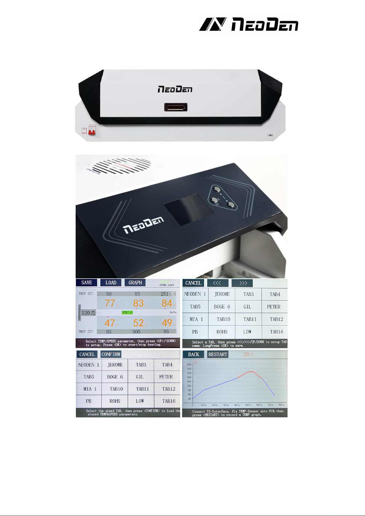
3. Main Parts
3.1 Reflow Oven Main Body
3.2 Operating Panel
3.3 Pedestal

3
4. Installation Instruction
4.1 Power Supply Connection
IN6 is used in 110V/220V single-phase connection mode and is connected according to the user
environment. Wires connection method is shown as picture. L stands for the live wire, N stands for
the zero wire, and E stands for the ground wire, connect to the 220V (110V) power supply.
According to the wiring requirements, the L should be connected to one live wire, and the N should
be connected to one zero wire; the E should be connected to one ground wire properly
4.2 Installation Attentions
♦Power supply requirement:110V/220V
♦For desktop reflow oven, should be working on workbench, don’t suggest to use wooden material
♦The machine should be set in standard SMT workshop, stay away from flammable and explosive if
couldn’t meet previous requirements.
♦Exposed wire harness should be well protected, prohibit to expose at the passage or flue in case of
causing any accident.
4.3 Status of Indicators
There is a green bar indicator at the PCB entrance that indicates whether the temperature in all
zones has reached the set temperature. This indicator lights up when the actual temperature of all
zones reaches the set temperature.
4.4 Operation instructions
♦Power-on
L N E

4
Turn the red power switch to the ON position and the machine starts.
♦Transfer chain speed setting
Tap the speed parameter on the screen and press the Up/Down button to set the appropriate transfer
chain rotation speed. When the speed is set, the time required to transport a PCB at this setting
speed is displayed on the right side of the screen.
♦Temperature zone setting
Tap the temperature parameter on the screen and press the up/down buttons to set the temperature.
Black is “the set temperature”, and orange is “the real-time temperature”.
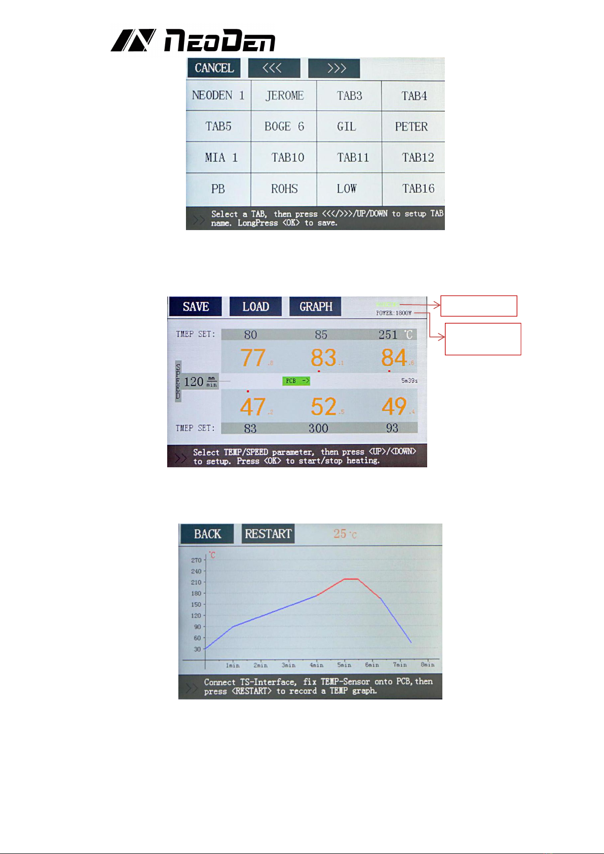
♦Save and Usage of speed and temperature settings
After setting the transfer chain speed and the temperature of each zone, you could press the SAVE
button to save the setting parameters of the transfer chain and the zone temperature. When the
SAVE button is pressed, it will enter the TAB interface. Click on a TAB, then you can use the
"<<<", ">>>" "Up" and "Down" buttons to change the TAB name, long press OK to save these
parameters to this TAB.
When you would like to call the previously saved speed and temperature of the transport chain,
click the LOAD button on the screen to enter the TAB interface, click the TAB name, and then click
the CONFIRM button to load the speed and temperature settings of the transport chain.
Speed setting
Time required
to transport a
PCB
Temperatur
e setting
Power switch
5
♦Start or stop heating
Press the OK button in the main interface, the machine will switch from STANDBY state to
WORKING state, and begin to warm up.
If you need to switch from WORKING state to STANDBY state, just press the OK button in
WORKING state.
♦Temperature curve
Connect the temperature sensor to the TEMP SENSOR connector, attach the temperature sensor to
the PCB, and then click the “Restart”button on the Graph interface after PCB is put into the oven
to get the temperature curve.
♦Power-off
Turn the red power switch to the OFF position and turn off the machine.
♦Change language and the unit of temperature in machine
After the power switch is turned to ON, the NeoDen logo will be displayed on the screen. Long
press the OK button to enter the Debug mode interface. In this interface, you can change the
language and temperature unit of the machine.
Working State
Real-time
Power size

6
5. Temperature wave setting principle
5.1 The reflow soldering theory and the temperature wave
When the PCB goes into heat up area (dry area), the solvent and gas in the solder paste will
evaporate. At the same time, the flux can wet the pad and the component tip and foot. The solder
paste melts, caves in and covers the pad, leading to the pad and component pins insulate the oxygen.
PCB goes into heat preservation area. PCB and components get full preheating. In case of damaging
the PCB and components when it goes into the welding area and the temperature heats up quickly.
When PCB goes into the welding area, the temperature heats up and the solder paste melts. When
PCB goes into cooling area, the liquid solder paste the soldering points solidify. The reflow process
is finished.
The temperature is the key to welding quality. The actual and the setting temperature warming slope
and the peak temperature should be accordant. Before the temperature reaches 160℃, please control
the heat up speed in about 1℃/S. If heat up too quickly, the PCB and the components will be
damaged, and the PCB may be out of shape. On the other side, the flux volatilizes too fast. And it is
easy to make soldering tin ball. Set the peak temperature 20℃-40℃higher than the solder paste
melting point. Set the reflow time 10S-60S. If the peak temperature is low or the reflow time is
short, it will affect the welding quality, and serious is causing the solder paste does not melt. If the
peak temperature is high or the reflow time is long, the metal power will be oxidized and affect the
welding quality and serious is causing the component and PCB damaged.
5.2 The set of the temperature wave
Set the wave according to the solder paste and the above foundation. Different solder paste, choose
and set different waves. In addition, the temperature wave has related to the PCB, the density and
size of components. Generally lead-free welding temperature should be higher 40℃than melting
point.
6. Details about temperature area setting
♦Set the temperature and belt speed to initial value, to the cooling oven, should be preheated for 25
minutes.
♦When the temperature is stable, let PCB pass heat reflow system. If there is no reflow, can
properly reduce the transfer chain rotation speed. Another way is that, do not adjust the speed, and
increase the temperature properly. When adjust the temperature, notice that it cannot exceed the
PCB and component bearing capacity.
♦Let the PCB pass the reflow system in the new speed or new set temperature. If there is no reflow,
turn to redo the above step. Otherwise, need temperature fine-turning.
♦The heat temperature wave is adjustable according to the PCB. You can adjust the transfer chain
rotation speed to adjust the temperature. Reduce the transfer chain rotation speed can increase the
product heat temperature. On the contrary, you can reduce the product heat temperature.
Attention:
♦If the PCB has been placed components, the PCB pass the reflow and it reflow not very completely,
suggest you adjust then reflow again. Normally, it will not impact the PCB and components.
♦From low to high when set temperature. If the heat range is over the reflow temperature too high,

7
should increase the transfer chain rotation speed or reduce the set temperature.
♦Different PCBs boards have different heat transmission rate and heat absorption capacity, so it
requires the reflow oven offers different heated time and quantity of heating. To double-side PCB,
multi-board and other PCBs with many bonding pads, they have a higher temperature setting. To
one-side PCB, paper board and less bonding pads’ PCB, they have a lower temperature setting. And
it also be affected by quantity of PCB that you place. During actual work, reflow oven will adjust
itself automatically to some changes of PCB. If based on our suggested temperature, the machine
can work well, unless very big change of PCB’s absorption capacity, then it needs to adjust
properly.
7. Temperature measurement method
♦Attach the temperature thermocouple sensor to the PCB which is the same or similar size as the
working PCB in order to observe the reflow. Put the PCB on the transfer chain, then will get the
temperature profile, after that compare with the recommend temperature profile. If it is the same to
the standard profile or correspond with automodulation profile, then you can start to produce,
otherwise follow the temperature profile, the temperature controller with large temperature
difference is used to set the compensation temperature by 5 degrees, or the whole machine
integrated adjustment, in order to achieve the temperature profile can be produced
♦When starting to put PCB or abruptly change the number of PCB to be reflow oven, there is a
difference between the actual temperature and setting temperature, put the PCB with constant speed
for a period of time, the temperature difference will turn to normal temperature difference range.
8. Both side soldering instruction
♦Use hot air reflow soldering can finish double-side component soldering. Double-side soldering
design means components are in double-side of the PCB need to soldering. Double side soldering
includes double-side soldering tin and single-side soldering tin and another side drying glue, as for
single-side soldering tin and another side drying glue, it is easier. First, finish one side’s soldering
tin as the same as single-side, then finish another side tape glue drying in low temperature, finish
double-side SMT craft, after that carry on the next step plug-in or tin process on craft. Double-side
soldering is generally treated as below follows:
♦Start the reflow oven, set up the transfer chain speed controller, finish the A side components
reflow soldering with normal soldering craft.
♦Upend the PCB, repeat normal procedure to mount the component, adopt top heating strategy to let
the B side reflow soldering, but the upend A side has been reflow soldering, the compounds in thick
liquid volatilize, the melting point of tin is higher than the solder paste, which in order to keep the A
side components not fall out.
9. Trouble shooting
9.1 Soldering analysis
Problem
Possible causes
Solutions be available
Incomplete
reflow
Inadequate heating
lower the transfer chain speed
Shadows from components
a. Increase the transfer chain speed
b. Increase bottom heat
Due to the middle layer of copper foil
Decrease transfer chain speed and increase
temperature
Inadequate
moist
PCB, components without enough solder
paste
Pre-paste to components and PCB
No enough moist time
Increase the temperature of heating zone
PCB bend
Exceeding upper and lower temperature
difference limits
Reduce temperature difference between
preheating zone and bottom temperature zone
Increase transfer chain speed
PCB
discoloration
Exceeding tin temperature on the board,
exceeding temperature gradient or
heating speed
Increase transfer chain speed
Decrease the preset zone temperature
Decrease transfer speed and temperature
Excessive fines
Top layer temperature out of limit
Reduce top heat and increase bottom zone
temperature
Tin balls
Due to dry too fast
Decrease transfer chain speed and temperature
Solder pasting is unqualified or PCB re-
Use PCB after cleaning and drying

8
paste
Flux coking
Over heating
Add transfer chain speed, lower temperature
Components
wrong position
PNP wrongly, the tin on the solder pad is
irregular or asymmetrical, drying too fast
causes airflow to blow components
Check place position
Check the shape and thickness of tin
Lower transfer chain speed and temperature
Tin bridging
Misposition
Check position
Tin migration
Moist overtime
Increase the belt speed
Lower pre-setting temperature
Solder skips
The solder paste is not enough on pad,
the unevenness of the micro-component,
the PCB coplanarity problem
Thickened tin paste coating
Try to make the solder on the pad even
Check component pin stability
PCB over heat
Heating speed too fast
Decrease transfer chain speed and temperature
9.2 Precautions
If the PCB length is longer than the ESD tray, the ESD tray needs to be replaced by other suitable
carriers to place the soldered PCB.
9.3 Machine maintenance
♦Change the filter regularly
It is necessary to replace the filter regularly. The service life of filter is 8 months (depending on the
frequency of use). When it’s needed to replace the filter, you could find the welding smoke
automatic filter system in the figure below. Remove the 12 screws above and replace the filter.
♦Regularly add high temperature lubricating oil to transfer chain bearings.
Table of contents
Other NeoDen Industrial Equipment manuals


Popular Industrial Equipment manuals by other brands

schmersal
schmersal AZM201Z-CC-T-1P2PW-DU Instructions for operation

HYDROSCAND
HYDROSCAND AutoReel Dynamic user manual

Bender
Bender EDS44 L-CN Series quick start guide

ABB
ABB A265-L Operation manual

Bosch
Bosch rexroth ActiveShuttle System manual

Current Tools
Current Tools 281 Assembly, Operating, Safety and Parts Manual


