NeoDen 7 User manual
Hangzhou NeoDen Technology Co.,Ltd.
7th Generation
High-Speed Pick and Place Machine
User Manual
Manufacturer: Hangzhou NeoDen Technology Co.,Ltd.
Applicable Model: NeoDen7 High-Speed Pick and Place Machine
Version: V1.01

Hangzhou NeoDen Technology Co.,Ltd.
Content
1. Brief Introduction.................................................................................................................. 1
1.1 Product Introduction........................................................................................................1
1.2 Structure of NeoDen7......................................................................................................2
1.3 Operation flow chart........................................................................................................3
1.4 Flow chart of making a programming file...................................................................... 4
2.Edit on the Operation Interface.................................................................................................. 4
2.1 Edit on the Interface........................................................................................................ 4
2.1.1 PCB feed settings................................................................................................. 5
2.1.1.1 Mag Fixture............................................................................................... 5
2.1.1.2 Rail............................................................................................................ 5
2.1.2 Panelized PCB origin (SMD1 coordinate)...........................................................6
2.1.2.1 Single board...............................................................................................6
2.1.2.2 Panelized board......................................................................................... 7
2.1.2.3 Mirror board.............................................................................................. 8
2.1.2.4 PCB angle correction................................................................................ 9
2.1.2.5 Skip marked panels................................................................................. 10
2.1.3 PCB fiducial setting........................................................................................... 11
2.1.3.1 Single fiducial......................................................................................... 11
2.1.3.2 Panelized fiducial....................................................................................11
2.1.3.3 Manual alignment....................................................................................11
2.1.3.4 Add or delete fiducial..............................................................................12
2.1.4 Component list setting........................................................................................13
2.1.4.1 Manual programming..............................................................................13
2.1.4.2 Secondary editing of components...........................................................16
2.1.4.3 Import the mounting file......................................................................... 17
2.1.5 Feeders setting page........................................................................................... 18
2.1.5.1 Feeder arrangement.................................................................................18
2.1.5.2Feeder information configuration............................................................ 18
2.2 File Mounting................................................................................................................ 20
2.3 Factory settings..............................................................................................................22
2.3.1 Feeder configuration.......................................................................................... 23
2.3.2 Nozzles’ Positions Setup.................................................................................... 24
2.3.2.1 Fiducial Camera Position........................................................................24
2.3.2.2 IC Camera Position................................................................................. 25
2.3.2.3 Flying Camera Position...........................................................................26
2.4 First trial and test...........................................................................................................27
2.4.1Program first dry run...........................................................................................27
2.4.2 First production test............................................................................................27
2.4.3 Component Inspection....................................................................................... 27
2.4.3.1 Inspection items...................................................................................... 27

Hangzhou NeoDen Technology Co.,Ltd.
2.4.3.2 Inspection method................................................................................... 27
2.4.3.3 Inspection standard..................................................................................27
2.5 Continuous SMT production.........................................................................................28
3.Structure and maintenance instruction..................................................................................... 29
3.1 Structure chart............................................................................................................... 29
3.2 Feeder Brief Introduction.............................................................................................. 30
3.3 Installing tape and reel components..............................................................................31
3.4 Incorrect installation Samples....................................................................................... 32
3.4.1 Nozzle.................................................................................................................33
3.5 Maintenance.................................................................................................................. 35
3.5.1 Take effective measures to reduce /avoid malfunction......................................35
3.5.1.1 Reinforce daily maintenance...................................................................35
3.5.1.2 Requirements for operator...................................................................... 35
3.5.1.3 Formulate the measures to reduce/avoid big problem............................36
3.5.2 Maintenance....................................................................................................... 36
3.5.2.1 Daily Inspection...................................................................................... 36
3.5.2.2 Monthly Inspection................................................................................. 37
3.5.3 Related issues during solder paste printing process.......................................... 37
3.5.3.1 Stencil Printing Technology.....................................................................37
3.5.3.2 Inspecting of solder paste printing.......................................................... 37
3.5.3.3 The defects of solder paste printing, reasons and solutions.................... 38


Hangzhou NeoDen Technology Co.,Ltd.
1
NeoDen7 User Manual
(High-Speed Fully Automatic Pick and Place machine)
1.Brief Introduction
1.1 Product Introduction
The seventh-generation model NeoDen7(Automatic universal visual pick and place machine)
is NeoDen Tech’s independent product, with completely independent intellectual property.
NeoDen7 has the advantages of fast speed, high accuracy, convenient operation, multiple
feeders, high efficiency, stable performance, convenient and simple operation. NeoDen7
features six independent flying HD cameras, one IC alignment camera and one independent
fiducial camera, perfectly implements standard mounting of components such as
micro-miniature components and fine-pitch IC under the premise of ensuring efficient
mounting; NeoDen7 adopts the most stable pneumatic feeder on the market, the advantages are
stability, easy replacement, easy installation, quick and convenient tape reel installation, it
matching with vision correction system and rail feeding system.
Maximum Board
Dimension
630*300mm(1200mm optional)
Number of Heads
Placement head:1 Nozzle:6
Max Tape Feeder
Capacity
64(8mm or 12mm feeder)
Applicable tape reel
feeder size
8mm,12mm,16mm,24mm,32mm,44mm,56mm
Average Placement
Speed
13,500CPH
Vision Number
8(1 fiducial camera, 6 flying cameras, 1 IC camera)
Component range
Smallest components:0402, TQFP, QFN, BGA and other
conventional components
Feeder Number
Tape feeder:64
Resolution
X/Y axis:0.01mm, Z axis:0.1mm
Rotation
±180°(360°)
Placement Accuracy
0.01mm
Power Supply
AC220V/110V
Power
500W
Machine Size
1420*1220*1665mm
Air Source
Above 0.6MP
Hangzhou NeoDen Technology Co.,Ltd.
2
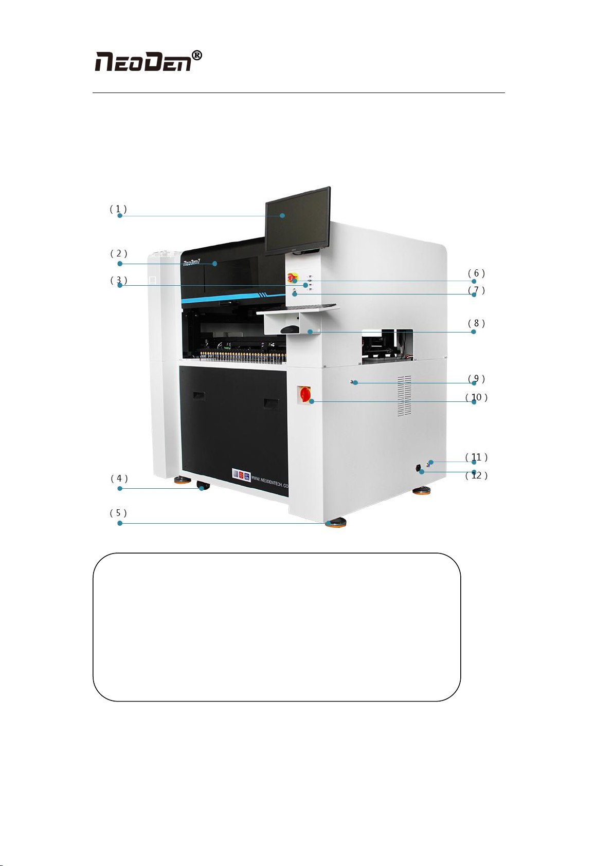
1.2 Structure of NeoDen7
(7)Pause button
(8)Mouse keyboard
bracket
(9)Conveyor Port
(10)Power Switch
(11)Air source input
(12)Power port
(1)12 inch high-definition
display
(2)Safety cover
(3)USB port
(4)Universal wheel
(5)Heavy load pedestal
(6)Emergency Button
Hangzhou NeoDen Technology Co.,Ltd.
3
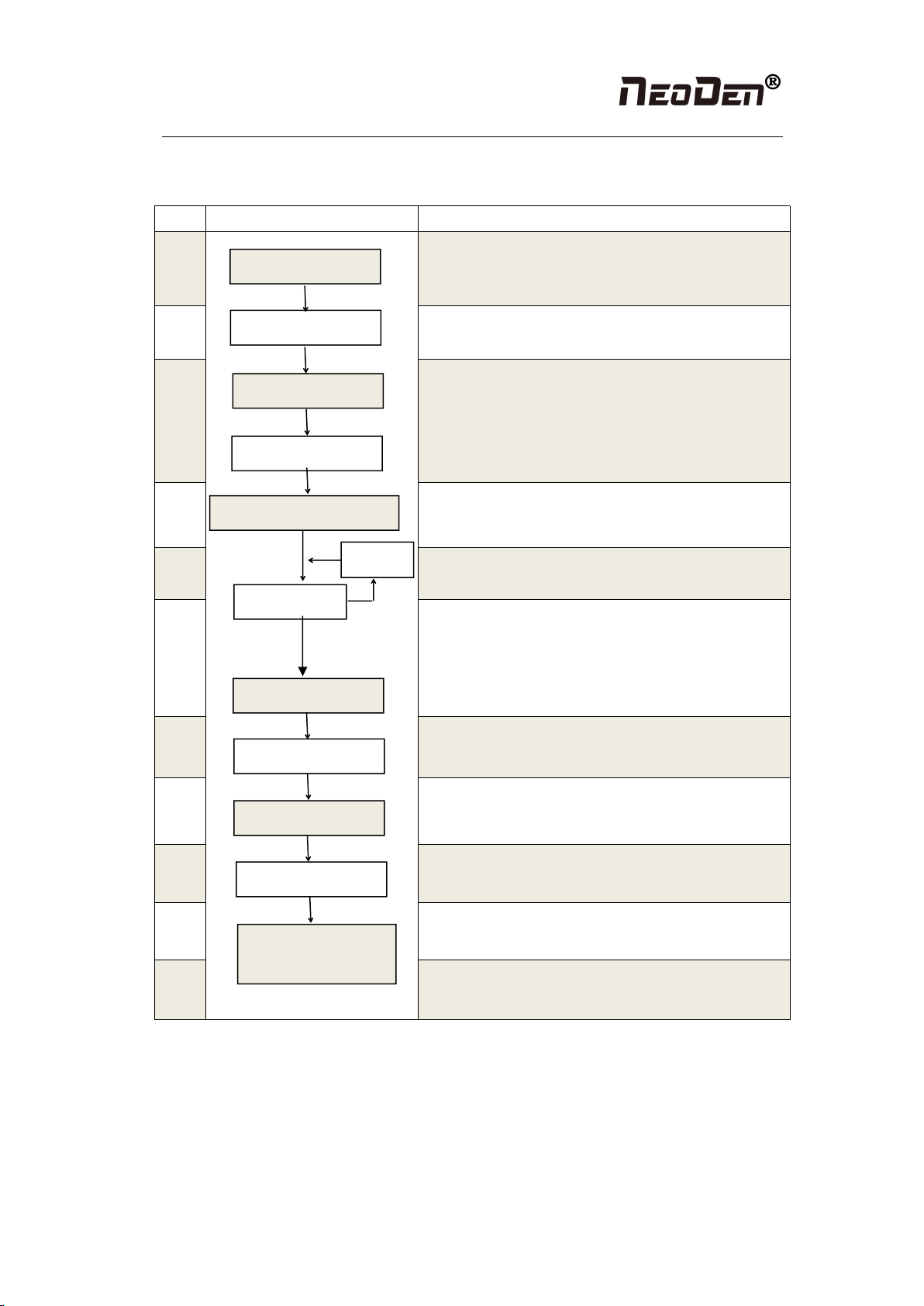
1.3 Operation flow chart
NO.
Flow chart
Note
1
Checking the working area whether it is safe or not,
whether the air source is normally connected and reaches
the calibrated pressure value.
2
3
Click the launcher icons, machine will start self-checking
process, you can see the flash board of the up-looking
camera is flashing, nozzle start initializing, and XY
initializing. After the initialization, machine will go into the
software interface.
4
After power on complete, machine will enter the file list
interface
5
Please refer to the detailed information on page
4—machine operation introduction
6
After making a programming file, it may exist several
programming issues, such as rotation issues of components,
so a production testing is necessary for solving issues.
7
Start to pick and place.
8
Production finish, exit.
9
Shut down the system via computer, then power off the
machine.
10
Disconnect the electricity supply after the system being
powered off.
11
Keep the machine clean, daily maintenance of the nozzles
assures high utility.
System shut down
Power off
Cleaning and
maintenance
Exit
Mounting
Preparation
Turn on
Initialization
Operation page
Edit
Normal
Test
Modify
Abnormal
Hangzhou NeoDen Technology Co.,Ltd.
4
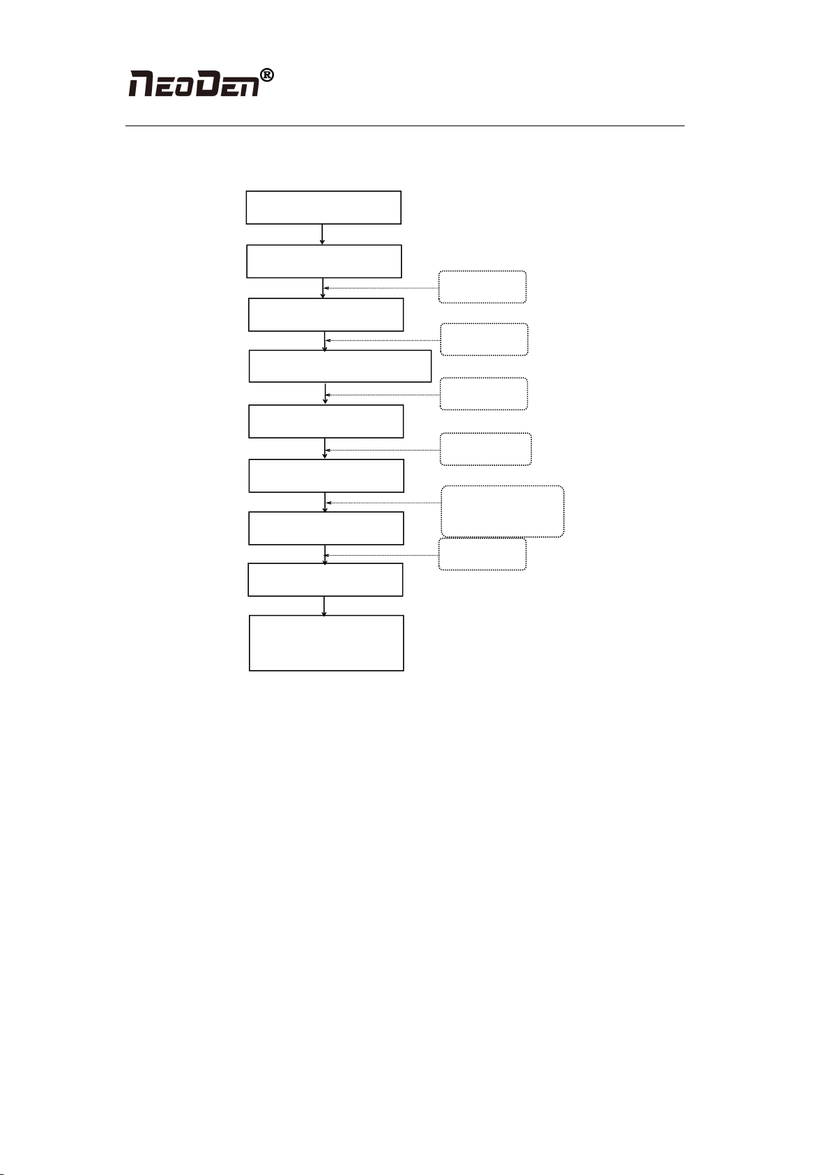
1.4 Flow chart of making a programming file
Component setup
Select file and start
working
Start
Panelized PCB first chip setting
Edit the file
PCB feed setting
Fiducial setting
Feeder settings
Save and cancel
See P6
See P12
Pick up simultaneously
setting
See P18
See P5
See P4
Note: The basic procedure of making a programming file by manual programming or import
coordinate file is similar, but there are two different parts: component list and fiducial setting.
Please find the detailed operation steps of the differences on relative page.
2.Edit on the Operation Interface
2.1 Edit on the Interface
See figure (2.1): On the file list interface, add a file and input the file name, select the file and
edit. Or edit the existed file.
Figure (2.1) is the edit interface
Hangzhou NeoDen Technology Co.,Ltd.
5
Figure (2.1)
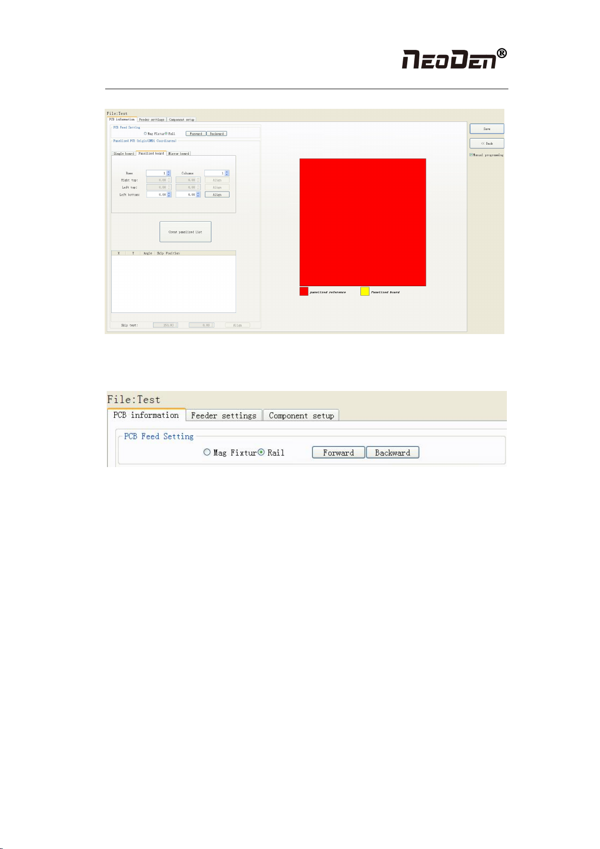
2.1.1 PCB feed settings
Figure (2.1.1)
Function: determine the PCB feed position. On the manual programming mode, it’s the
primary edit item, see figure (2.1.1)
2.1.1.1 Mag Fixture
When you select “Mag Fixture”, the function key of PCB feed setting and setting operation
part will be banned. We only need use positioning pins to fix the PCB.
2.1.1.2 Rail
First select the “rail”, the setting operation part will be available.
Operation steps: first adjust the rail width to let the PCB can move smoothly on the rail.
Click “feed”, PCB will move through the sensor to the cylinder thimble position, cylinder will
raise the PCB, then thimble will go down, PCB feeding complete. (If need adjust the PCB
feeding position, need adjust the thimble and rail sensor position)

Hangzhou NeoDen Technology Co.,Ltd.
6
2.1.2 Panelized PCB origin (SMD1 coordinate)
Figure (2.1.2)
Function: This is mainly to determine the first component on single or panelized PCB of
manual program or imported file. The principle is to collect and calculate the data of each
board’s relative spacing, in order to achieve the calculation of the real coordinate.
Note: the panelized PCB origin (SMD1 coordinates) and panelized list setting of the
manual program mode is the same as file import mode.
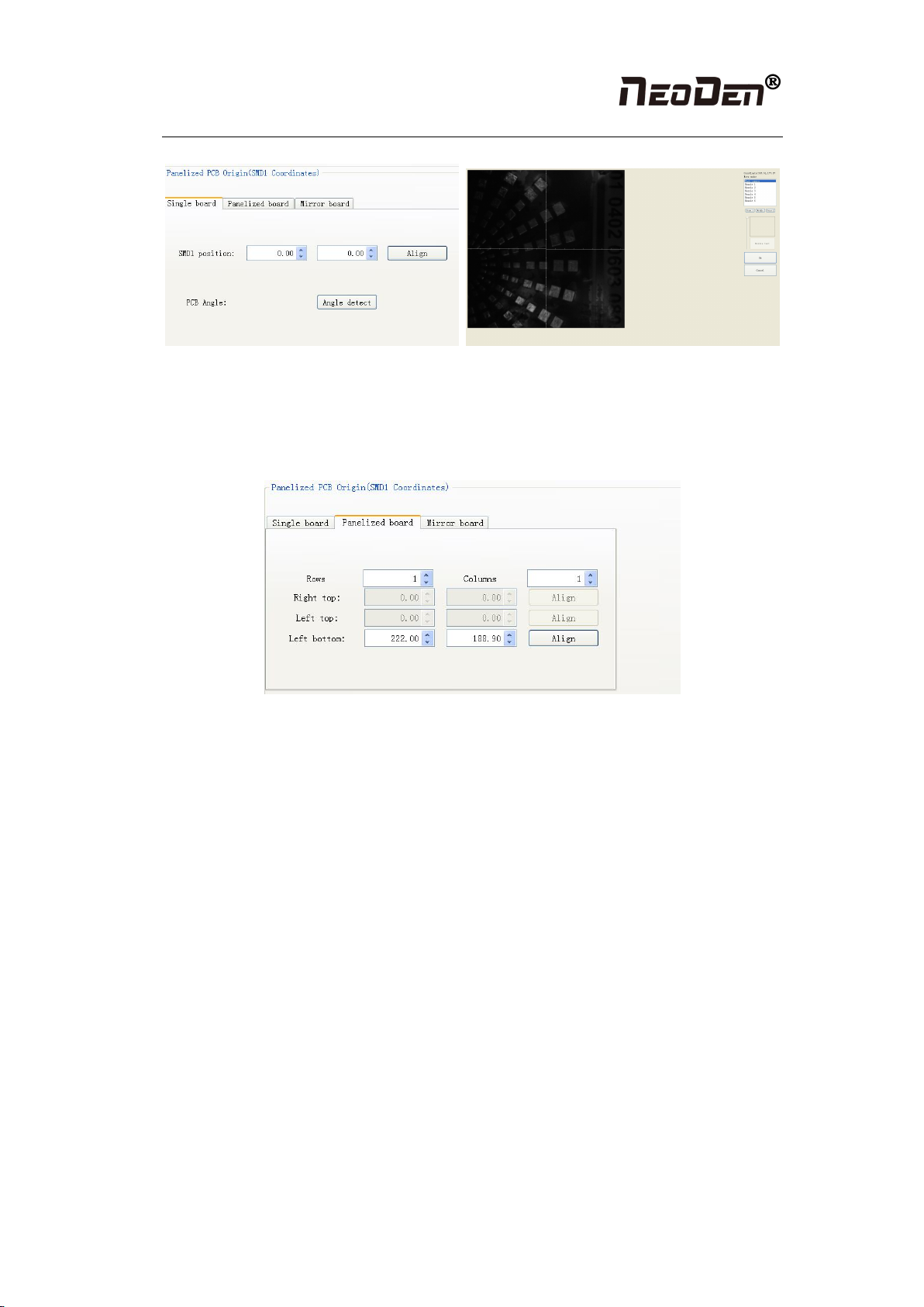
2.1.2.1 Single board
Click “single board setting”, you will see the “align” button of the SMD1 position that means
the first component on the component setup. Click “align” to enter the vision align interface,
we need find the first component that on the component list, normally we choose the center of
the component, see figure (2.1.2.1)
Hangzhou NeoDen Technology Co.,Ltd.
7
Figure (2.1.2.1)
Click “ok”, it will back to the previous interface, click “create panelized list” button”, the data
which on the panelized list will change.
2.1.2.2 Panelized board
Figure (2.1.2.2)
The steps of the panelized board programming are similar with the single board, but need pay
some attention to several points below
●The row and column are determined by the positioning of PCB on working area. The
direction along the rails is the column, the direction perpendicular to the rail is row, then please
enter data in the row and column.
●About the data collection of “left bottom”, “left top” and “right top”, we should take the
“left bottom” as the basic, and then go to set “left top” and “right top”. Once all the data are
collected, the machine can calculate and process the information of panelized board.
Please refer to the data collecting method of each position information as following:
●The data of “left bottom” is collected according to first component in the component list of
programming file. Press “align” of left bottom, find the left bottom panel that is nearest to the
left side and nearest to the feeding position, then find the first component which on the chip list
of this panel, align the center of this component. After saving the data, it will return to the
“PCB information” automatically.
●The data of “left top”: on the alignment interface, find the left top panel that is nearest to the
left side but farthest to the feeding position, then find the component same as the component
that aligned on the “left bottom”, align the center of this component. Click save and cancel, it
will return to the “PCB information” automatically.
●The data of “right top”: on the alignment interface, find the right top panel that is nearest to
the right side but farthest to the feeding position, then find the same component as the
Hangzhou NeoDen Technology Co.,Ltd.
8
component that aligned on the “left bottom”, align the center of this component, click save and
cancel, it will return to the “PCB information” automatically.
After setup, click “create panelized list”, the panelized list will be generated accordingly in the
blank. You can also double-confirm each position by clicking “Align”.
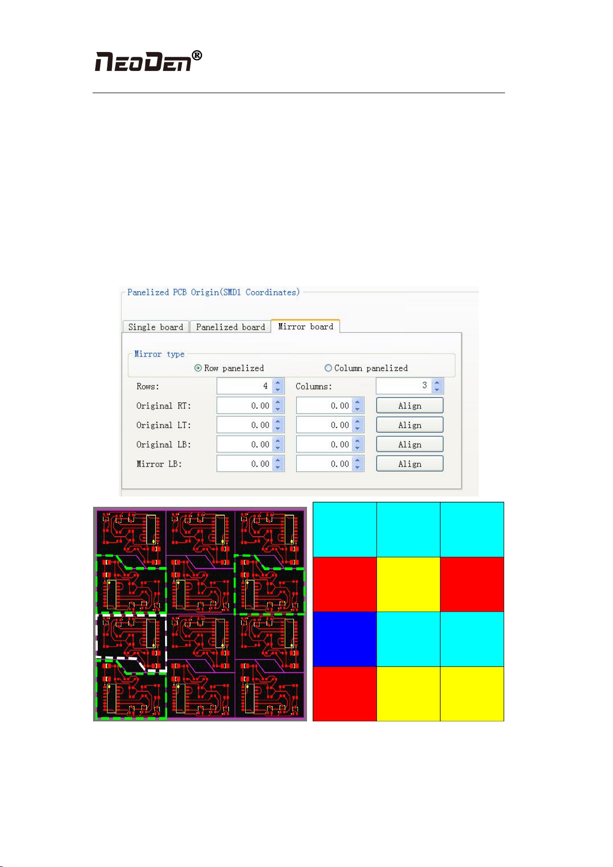
2.1.2.3 Mirror board
Mirror board includes row panelized and column panelized
Row panelized: several same PCBs are arranged in horizontal direction, and the nearby rows
are mirrored
Column panelized: several same PCBs are arranged in vertical direction, and the nearby
columns are mirrored
4
4
4
4
4
1
1
1
2
2
2
3
No.1 red areas are original ref
No.2 yellow areas are original boards
No.3 blue area is mirror ref
No.4 light blue areas are mirror boards

Hangzhou NeoDen Technology Co.,Ltd.
9
Figure (2.1.2.3)
No.1 red areas are original ref
No.2 yellow areas are original boards
No.3 blue area is mirror ref
No.4 light blue areas are mirror boards
Based on actual board to choose an applicable model of panelized mode. Figure (2.1.2.3) left
side is the arrangement way of mirror board and right side is the mirror board showing on
computer.
2.1.2.4 PCB angle correction
PCB angle will influence the accuracy of mounting. The angle closer to 0 degree the better,
and the angel deviation need to be within 1 degree. The angle of PCB is generated according to
panelized PCB coordinates, but we can also adjust the angle by manual. Click “PCB angle”
button, according to the index of machine to choose two points, then a new PCB angle will be
1
3
1
4
2
4
2
4
2
4
1
4
Hangzhou NeoDen Technology Co.,Ltd.
10
generated. (Note, the two points need to be paralleled)
Under panelized PCB model, “PCB angle” is locked. You need to correct from panelized PCB
to single PCB (1*1), after confirm the PCB angle, you can change back to panelized PCB
model.
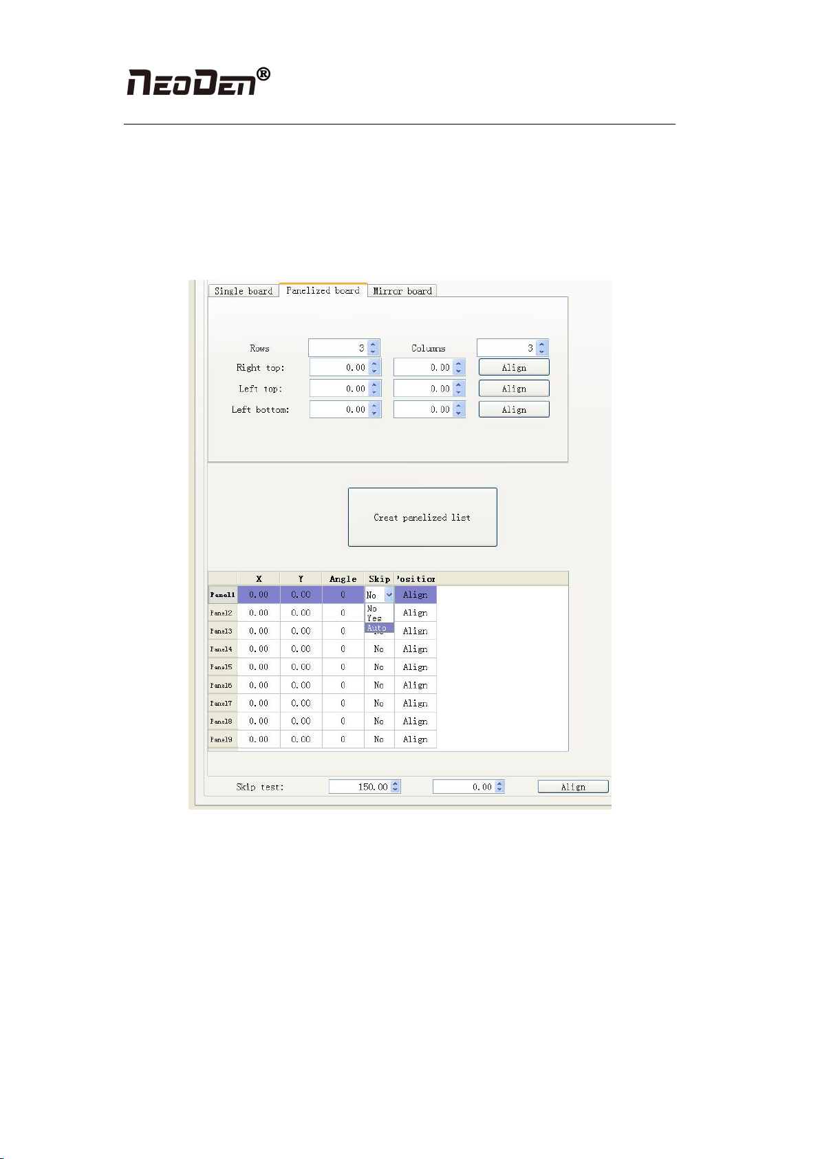
2.1.2.5 Skip marked panels
Figure (2.1.2.4)
Function: detect marked panels in multiple boards and skip marked panels
Steps:
(1) According to actual panelized PCB to generate panelized list
(2) Choose “Auto” from “Skip” option of panelized list
(3) Click “Align” button of skip test to choose one fixed position and mark it, thus every
time when machine scan this mark, it will skip this bad board.
The conventional practice is to stick a black label to the fixed position (the position that
you aligned on the skip test) on the board. If the label is attached on one panel, this panel
will be automatically skipped. And if the label is not attached on one panel, this panel will
be normally placed.
Hangzhou NeoDen Technology Co.,Ltd.
11
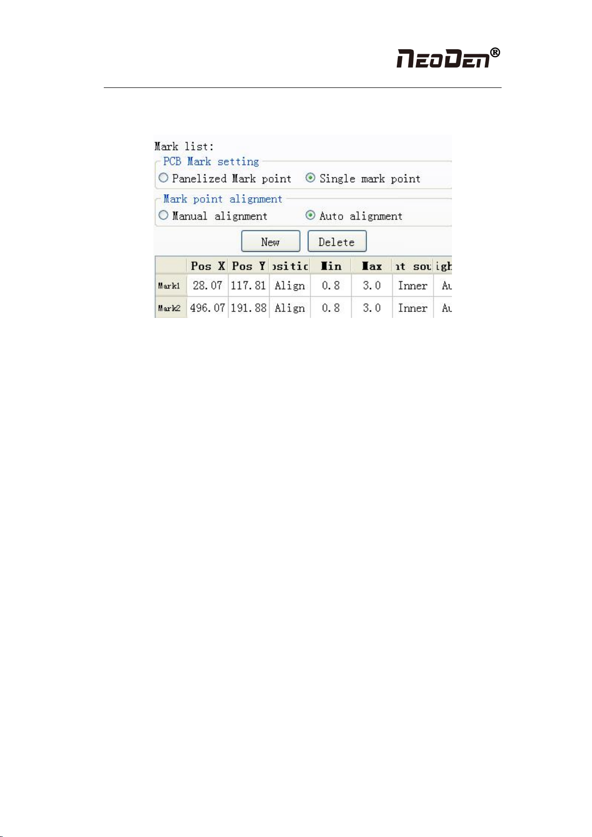
2.1.3 PCB fiducial setting
Figure (2.1.3)
Function: After finishing fiducial setting, when the machine is working, the specific position
and direction of PCB can confirm via setting fiducial. Only in this way the next step of
mounting work can carry out.
2.1.3.1 Single fiducial
It is mainly used for a single PCB board and multiple identical PCB boards consistent of the
whole board (Notice: coordinate programming is done as a single board)
Generally, need to select 2 or 3 fiducials.
2.1.3.2 Panelized fiducial
It is mainly used for multiple identical PCB boards consistent of the whole board, when place
every panel board, the machine will rescan small panel board’s fiducial.
2.1.3.3 Manual alignment
If there is no fiducial on the PCB, which can through some location holes and set up some
special reference point manually to replace and confirm reference position.
Hangzhou NeoDen Technology Co.,Ltd.
12
Figure(2.1.3.3)
●Import the coordinate automatically status: the data collection of fiducial, which through
PCB circuit board to find fiducial coordinate information directly, and input directly. Moreover,
there are some information about min, max, light source and brightness in the fiducial list.
◆Min, max value: means the size of fiducial, it has a floated value, which can prevent
recognizing fiducial wrongly.
◆Light source: Dividing into inner and external, if select the hole as fiducial which need
to choose the inner of light source; If select bright spot as fiducial which need to choose the
external of light source.
◆Brightness: The default automatic is generally used, only in special cases need to
change the value
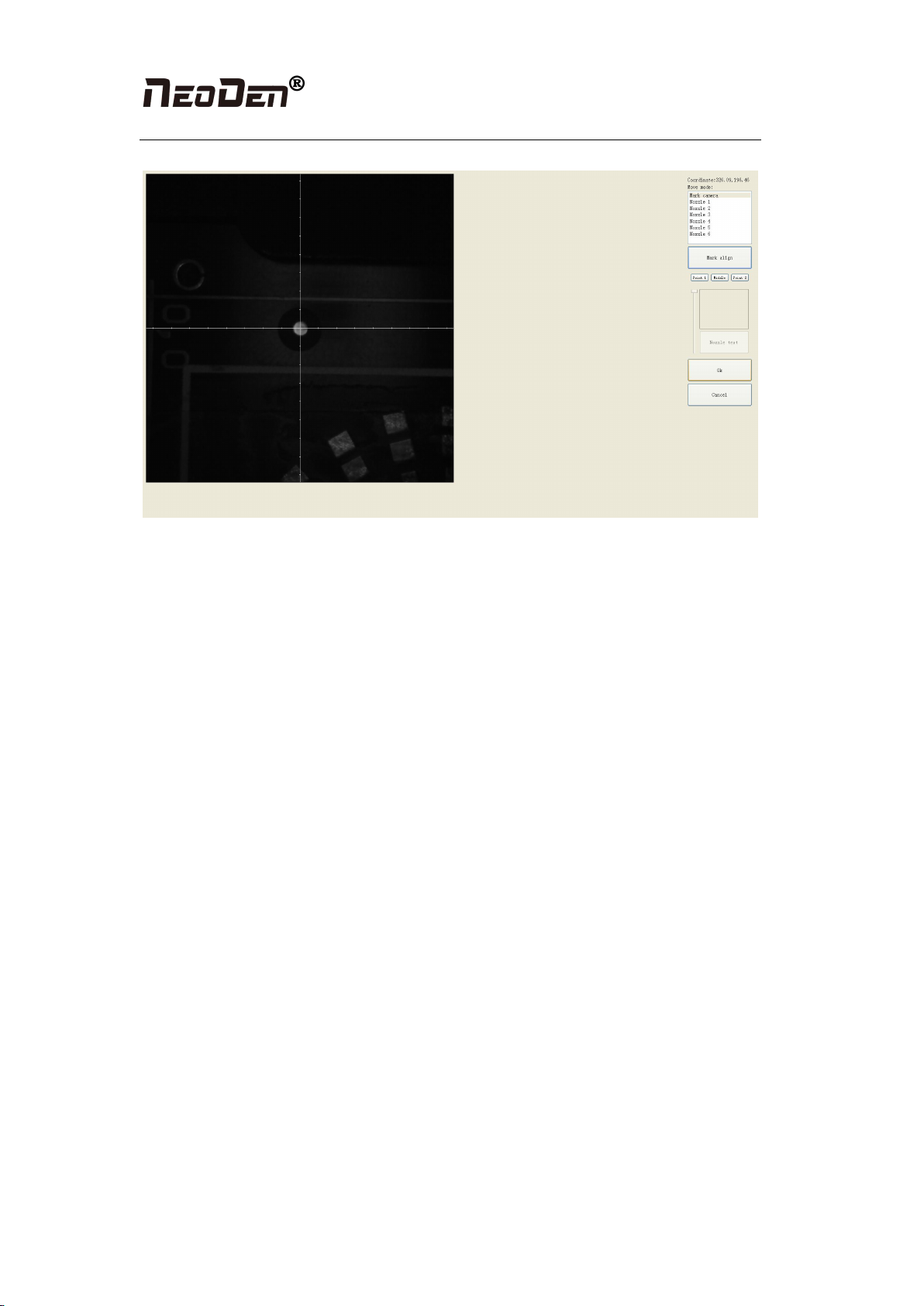
●Manual programming situation: the data collection of fiducial, on the manual programming
status, select the fiducial in the list and click “align”, see figure (2.1.3.3), enter image capture
page, and find the fiducial center via movement, click “fiducial align”, see figure (2.1.3.3),
then click “save”, go back to main page. Another Items (min, mix, light source, brightness)
setting is the same as the above (import automatically) operation. (if need long distance
movement, select visual field to move)
●Manual alignment situation: if there is no available information to set fiducial, we will
choose manual recognition. Notice: Generally, select the first component of mounting
component, select fiducial which is far away with first component and is easy to find, when
setting up like this, the relative mounting result will be better, after reloading process, it needs
to confirm manually.
2.1.3.4 Add or delete fiducial
●Add the quantity of fiducial
●Delete fiducial: when meet fiducial setting wrongly or reset up, tick it and delete directly.
Hangzhou NeoDen Technology Co.,Ltd.
13
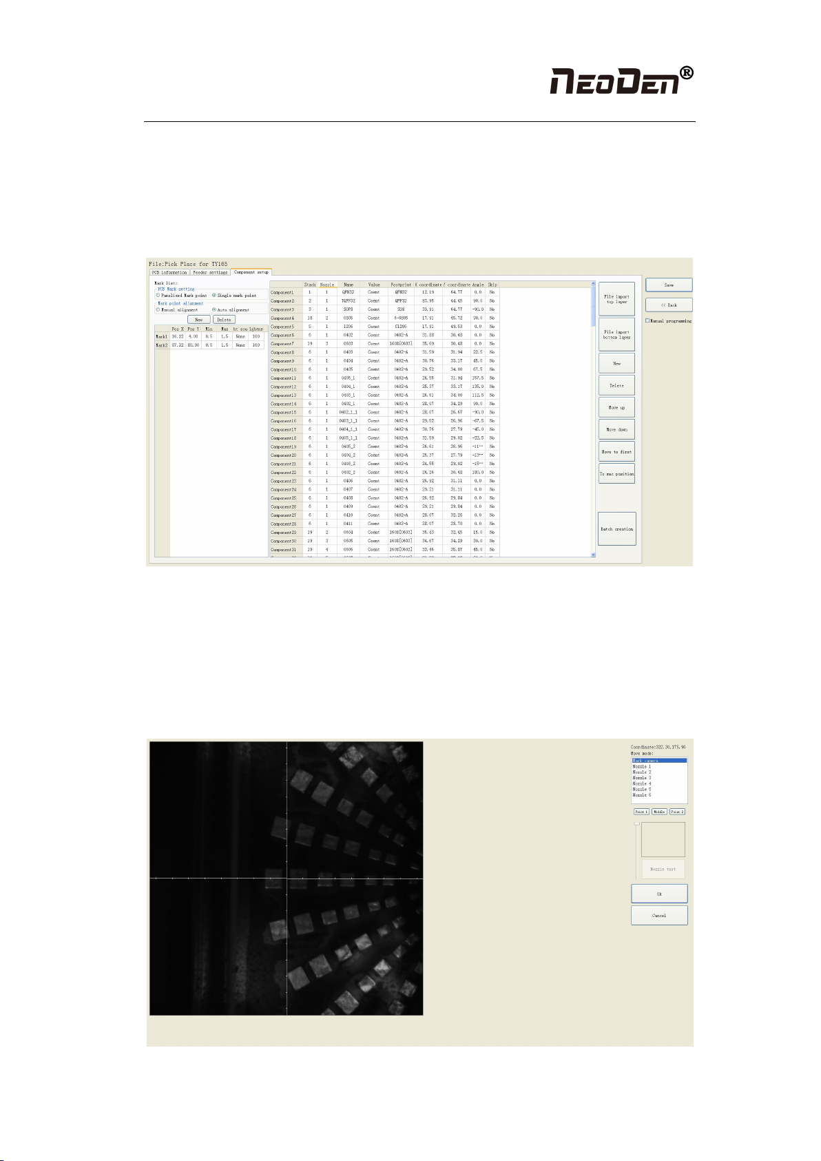
2.1.4 Component list setting
Function: display the information of mounting component, the mounting order of component,
which can via manual programming or import process file to add component quantity and
mounting information, see below figure (2.1.4), operation method:
Figure (2.1.4)
2.1.4.1 Manual programming
●Component edit firstly
Firstly, select manual programming, there will be a row of example components in the
component information, modify the sample component and click position “align”, the page
will switch to the vision of up-looking camera automatically, see figure (2.1.4.1)
Figure (2.1.4.1) note: a component diagram has been found
Hangzhou NeoDen Technology Co.,Ltd.
14
We can move down-looking camera or nozzle 1 and nozzle 6, find corresponding component
and confirm the component center coordinate, after clicking “save”, go back to main page,
then input related component information (Notice: name refer to component bit number,
specification refer to component value, footprint refer to common footprint name. Like
0603,0805,1206 etc. The angle is based on the placement direction of component on the circuit
board to confirm, transverse is 0 degree or 180 degree, vertical is 90 degree or negative 90
degree, which is mainly based on the polarity of component, degree must be integer degree;)
after all parameter setting, the first component information has been finished; click the “new”
in next step, the component list will add a row, coordinate information will entirely copy
adjacent up row, then click “align” to find the next component center, ensure to modify, reedit
name, specification, footprint, angle and etc., after finish it, continue to reedit until all edit
finish.
●Component movement
During the process of edit, sometimes, need to do a slightly adjustment for the edited file, we
have three types
(1) move up: The main thing is to move the selected components upward
(2) move down: The main thing is to move the selected components downward
(3) move to head position: The main thing is to move the selected components to the head
position to place.
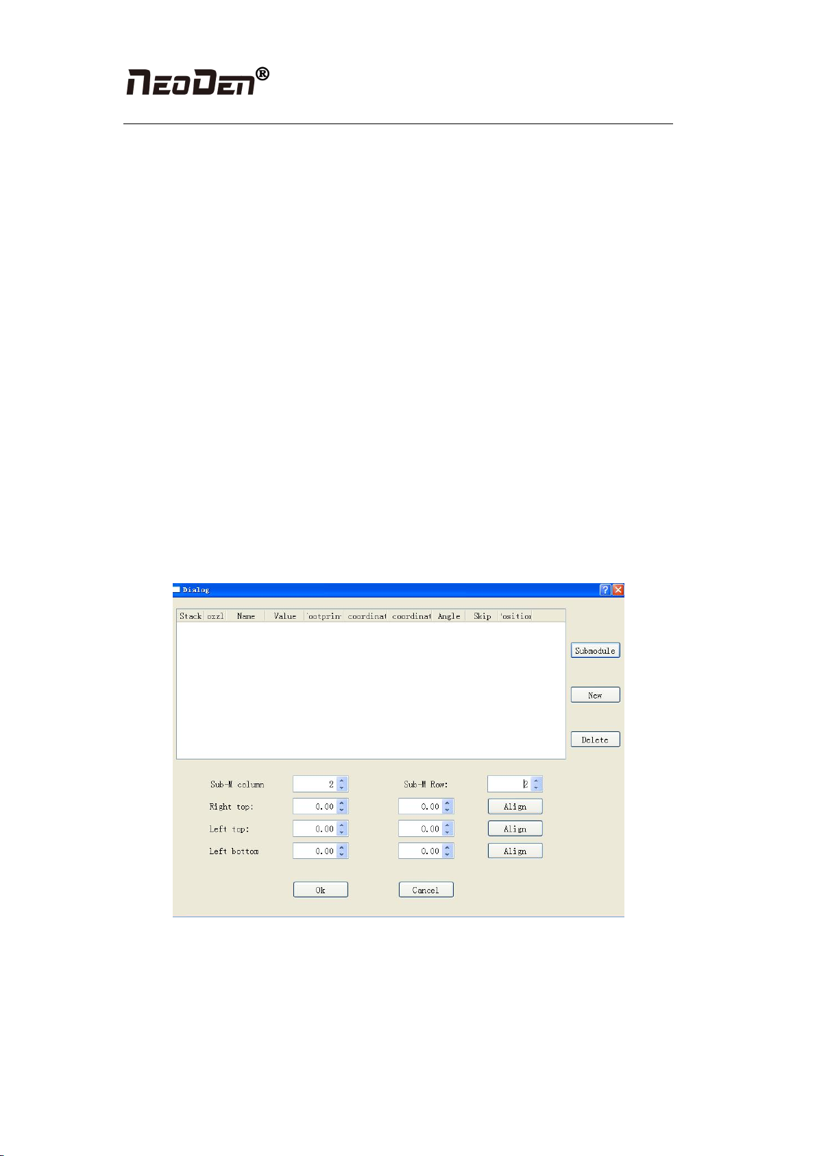
●Batch generate component
Figure (2.1.3.2-3)
Some circuit board is relatively regular and easy in actual edit, as for this type circuit board,
we can through mass production to generate coordinate file, the PCB as shown in figure
(2.1.3.2-3), we can see that it has a rectangular region and a circular region together to form a
small panel. We call this compositive panel as submodule. We can generate this small
imposition through submodule generation. We find it is consisting of 2 rows and 2 column,
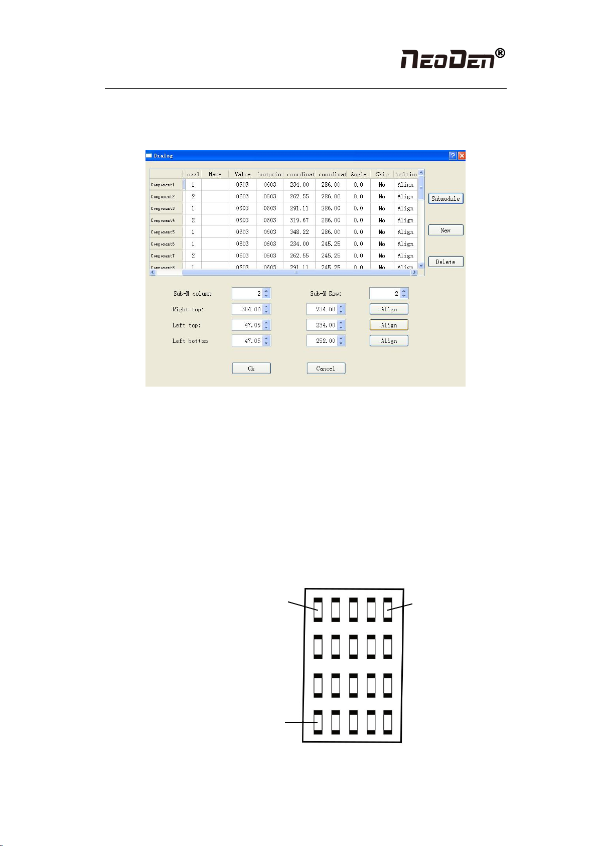
Hangzhou NeoDen Technology Co.,Ltd.
15
input 2 rows and 2 columns, find 3 head components, after finishing generating it, the
submodule is shown in the figure: we also can select stack, nozzle, name, specification and etc.
to adjust in this page.
Figure (2.1.3.2-4)
There are two ways to submodules can be produced in batches, one is a rectangle, the other is a
circle
①The way to generate rectangle panel: an example is shown as figure (2.1.3.2-5), click:
“producing component in batches”, which will appear a project is shown as figure (2.1.3.2-5),
component specification and component footprint need to input the specification and footprint
what you need. If you look at this lamp panel figure, we can see that it's uniformly symmetric
in four rows and five columns. We can add 4 rows and 5 columns in the row, column of the
machine, follow the tips to find the 3 points orderly to align. The component degree will be
based on actual situation to choose. (Notice: this angle here is the angle in the stack setting, the
default value is 0, follow the actual situation to modify. Click generate, the machine will
automatically generate all components’ coordinate in the figure (2.1.3.2-5)
右上角
左上角
左下角
Figure (2.1.3.2-5)
Top right corner
Top left corner
Lower left corner
Hangzhou NeoDen Technology Co.,Ltd.
16
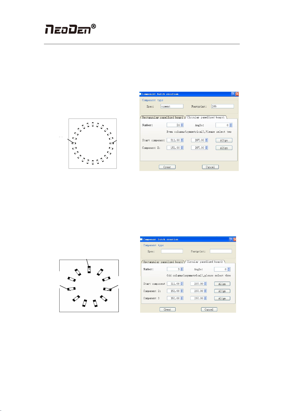
②The way about how to generate the circle panel when the component number is double
number: the project and rectangle of the “component type “are the same, we know it has 24
components by observation, the default angle is 0 here, input this value on your own. Because
if the total component is double number, we only need to find two symmetry to align. Click to
generate the 24 components coordinate in the circle panel.
起
元 器
Figure (2.1.3.2-6)
③The way about how to mass generate the circle panel when the component number is
single number: item in the type of components is the same as mentioned above, the circle
panel is shown as figure(2.1.3.2-6), after observing the panel, we know it has 9
components , because the final number of components is single, it is better to find 3
components that are isosceles triangle, and then align the coordinates of those three points
in turn. Click to generate 9 components’ coordinate in circle panel.
起 始
点
元器件
2.1.4.2 Secondary editing of components
Function: add or alter for the information of components based on exist programming
Procedure: firstly, enter into the program edit page, see figure (2.1.4.2):
Put the PCB board into rail which is corresponding with programming, click the “feed” in the
access setting area, confirm the PCB at the designated place, then click “transform into
machine’s current coordinate” and confirm it, at this time, the machine will automatically scan
the fiducial and transform all existing components’ information into current coordinate
Initial
point
Compo
nent
point 2
Initial
point
Component point 2
point 3
Table of contents
Other NeoDen Industrial Equipment manuals


