NeoDen YY1 User manual

1
NeoDen YY1
Automatic Pick and Place Machine
User Manual
Model:NeoDen YY1 Automatic Pick and Place Machine
Version: V1.0

2
Note!
In order to make your experience with the NeoDenYY1 better,
please read this manual in detail before using the machine, fully
understand the function and use of each part of the machine,
and operate it according to the manual's requirements.
Cautions
1. Please work with the machine in normative environment, make sure no direct
sunlight irradiation, otherwise it will reduce the machine service life and cause
camera recognition failed.
2. It’s better to wear anti-static clothing when operate the machine. Strong static may
bring interference to the screen and the IC on the PCB.
3. Keep machine in regular maintenance and cleaning. Please also make sure no
water or hand touch on the X/Y guide rails in case any rusting.
4. Please make sure the machine under power- off status while you need any machine
inside operation , in case any harm to the hands.
5. Make sure no any dirty things like solder paste stick on the nozzle, otherwise it
will have influence on placement effect, please keep nozzle clear.
6. With old chips or devices, the pins are easily darkened by oxidation and are not
easily recognized by the camera, so please try to use new devices.
7. Helps can be found on many pages with icon ‘?’, you can click it to get related
information.
8. Should any difficult issue, please contact us freely, we’ll supply assistance in time.
Uses
1. Please do not use the machine for any other purpose. Otherwise we are not
responsible for any liability arising therefrom.
2. Please do not modify the machine. We are not responsible for any accidents caused
by modifications.

3
Unpacking Instructions
Please follow the instructions for unpacking:
Step 1: Please remove the packing such as gin tape, pearl cotton etc.
Step 2: Raise the upper part of the machine case.
① ②
Step 3: Installation of acrylic cover.

4
Catalog
1. Machine Overview ................................................................................................... 5
1.1 Machine Dimension ........................................................................................ 5
1.2 Machine Structure ........................................................................................... 6
2. How to Quickly Place Your First Board .................................................................. 7
3. Software Interfaces Introduction .............................................................................. 9
3.1 Home Page and File List................................................................................... 9
3.2 File Editing Page............................................................................................. 10
3.2.1 Edit Component.....................................................................................10
3.2.2 Edit Fiducial.......................................................................................... 11
3.2.3 Panelized PCB.......................................................................................12
3.2.4 Mount.................................................................................................... 13
3.3 Manual Test.....................................................................................................14
3.4 Feeder Settings................................................................................................ 15
3.4.1 Tape Feeder........................................................................................... 15
3.4.2 Flexible Feeder...................................................................................... 16
3.4.3 Bulk Feeder........................................................................................... 16
3.5 System Parameters.......................................................................................... 17
3.5.1 Basic Parameters................................................................................... 18
3.5.2 Head and Needle Calibration................................................................ 19
3.5.3 Up-looking Camera Calibration............................................................ 21
4. Machine Operation Introduction.............................................................................. 24
4.1 PCB Fixing Methods....................................................................................... 24
4.2 Install the Tape Reel........................................................................................ 25
4.3 Stick Feeder.....................................................................................................26
4.4 Short Tape Reel Feeder................................................................................... 27
4.5 Nozzle and Auto Nozzle Replacement............................................................28
4.5.1 Introduction and Selection of Nozzles.................................................. 28
4.5.2 Auto Nozzle Change..............................................................................30
4.6 Vacuum Detection Module............................................................................. 31
4.7 Trash Box........................................................................................................ 33
4.8 Magnetic Acrylic Cover.................................................................................. 34
5. Machine Adjustment Guide and Maintenance......................................................... 35
5.1 How to Adjust the Peeling Force.................................................................... 35
5.2 How to Adjust the Shrapnel of Tape Feeder................................................... 35
5.3 How to Adjust the Belt Tightness................................................................... 36
5.4 Daily Maintenance.......................................................................................... 37

5
1. Machine Overview
1.1 Machine Dimension
Figure 1-Machine dimension drawing

6
1.2 Machine Structure
Figure 2-Schematic diagram of machine structure

7
2. How to Quickly Place Your First Board
Quick operation flow chart
1. You have two ways to generate placement files, export csv files through EDA
design software or manually create new ones.
2. Before exporting the csv file, you need to set the lower left corner as the origin
point (the Bottom layer is the lower right corner), as shown in Figure A.
3. After the EDA software exports the form file, please open it on the computer to
confirm the components information, you can delete some useless information such as
plug-in components, but the format cannot be changed.
4. Copy the csv file to the SD card and insert it into the machine to do following
operation. If the format is correct, the machine will read and convert the csv file
information.
5. On the machine, the necessary steps are: Load components > Feeder settings >
Component editing > Placement.
6. Fiducials and panelized boards are optional, can be set according to the page
instructions if necessary.
7. When place the first board, use the "step" function to try to place a few
components firstly, and after confirming the settings and placement files are both
correct, then can be automatically placed. You can also stick double-sides adhesive
tape to verify the first board (if the fiducials are set, the double-sides adhesive tape
cannot cover the fiducials).

8
8. The "Add New" button can manually create a standard YY1 csv placement file,
and then you can add and modify components on the component editing page.
9. You can also get your PCB placement file by modifying the standard YY1 csv
placement file on the computer. Note: The coordinates cannot have negative numbers,
and the angle range is 180 degrees to -180 degrees; other original formats cannot be
changed.

9
3. Software Interfaces Introduction
3.1 Home Page and File List
After initializing, it will turn to the Home Page ( Fig.YY1-01). Left side will
show the files which exist in SD card and right side are three buttons for interfaces of
“Manual Test”, “Feeder Settings” and “Parameters”. On the right top corner, there’s a
“How to begin” guidance to help users start programming quickly.
YY1-01
If without SD card inserted, the left side file list will be empty and the “Add new”
button is also unworkable. After SD card well inserted, all files will be automatically
show up and users can also create new file through the “Add new” button (Fig.
YY1-02)
YY1-02

10
3.2 File Edit Page
As previously referred, the CSV coordinate file can be directly imported into
machine through SD card for programming. What we must take notice is the correct
CSV file will be automatically converted to the related format while loaded but if
there’s error warning, it should be the file format wrong or the file was generated by
some unsupported EDA. Click correct file, you can continue programming or
placement process.
3.2.1 Edit Component
When you click “Edit Component”, it will turn to below interface. There’re some
tips for ref. during your programming:
1. All information in this area is related to feeder, generally for same kind of footprint
setting, you can directly click “Apply all same components”, then the six parameters
in this area will be workable for all of the same footprint.
2. You can modify parameters of the components one by one, and you can also
modify the parameters by using “Apply all same components” to realize modify the
same kind footprint components quickly.
3. If the component specifications are the same and the component footprint is also
same, they will be classified as the same type of components.
4. There are five recognition modes:0 (Null), 1 (Camera), 2 (Vacuum), 3 (Camera+
Vacuum), 4 (Big IC Camera). You can select the applicable mode for different
components to realize a balance between speed and accuracy. When you select 4,
the field of view area will be enlarged. Please make sure there’s no direct- light above
the machine otherwise it will affect the recognition, you can cover something on the
machine to escape the direct light.

11
3.2.2 Edit Fiducial
PCB will be fixed manually by the magnetic pin or bars and you also need to set
a fiducial for helping recognition. Some tips for setting fiducials:
1. Fiducial requirement: round shape, it could be pads or holes with high contrast to
the surrounding area (observed in the camera). You will hear a ticking sound if the
machine fails to recognize fiducials, you can try to replace to a more suitable one. It
will be generated as fiducial once it succeeds.
2. Please avoid any similar round shapes near the fiducials to avoid confusion,
otherwise the machine will take the other one as a fiducial.
3. Inaccurate setting of fiducials will result in overall offset in the same direction.
4. In Step1, if it’s not easy to ovserve the center of the component, please press the
button to move to next component until you can clearly align the center of a
component.
5. If the fiducial cannot be successfully recognized during placement, you can adjust
the camera threshold.

12
3.2.3 Panelized PCB
The way to set up the panelized information is very easy and intuitive. You just
need to input the horizontal and vertical dimensions of the PCB, and the number of
panels in horizontal and vertical directions.

13
3.2.4 Mount
After you click Mount button, it will enter this interface.
1. Press Step button to enter the Preview mode, then the related buttons will turn
green (active).
2. If you have set fiducial, the machine will go to recognize the fiducial before
entering the Preview mode after clicking Step button.
3. In the Preview mode, press the Align or buttons to locate the corresponding
component, you can also directly enter the designator to quickly locate the desired
component.
4. In the Preview mode, you can press the Up, Down, Left and Right buttons to
fine-tune the component position. Pressing the Save button will save all the
adjustments made this time. The rotation of the current component can also be
adjusted.
5. In the Preview mode, input the designator and then continue to mount, it will start
to mount from this component. This function can realize to start mounting from
midway or mount a certain individual component.
6. Sometimes the machine will have unavoidable mechanical offset, causing the
deviation between image position and the actual placement position, so the fine-tune
is more concerned about how much it has been off, not necessarily the center point of
the image is aligned with the center of the component.
7. Please avoid similar round shapes near fiducials to avoid confusion, otherwise the
machine will take the other one as fiducial.
14
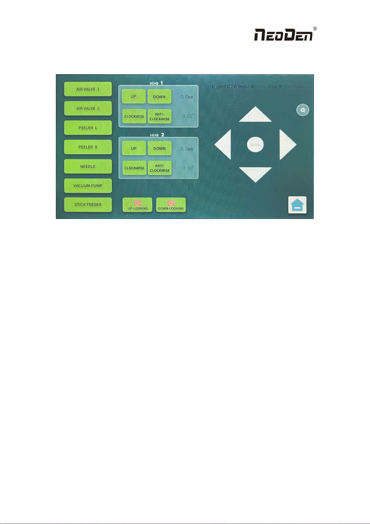
3.3 Manual Test
Click the orange button in the home to enter the Manual Test interface.
You can click any buttons in this interface to test if each module is functional.
(1)AIR VALVE 1/AIR VALVE 2: used to check if the valves are working.Please click
to open the vacuum pump before testing the air valves.
(2)PEEL L/PEEL R: used to check if the peeling gadgets are working normally
(3)FEEDER NEEDLE: used to check if the needle module could move down and
bounce back smoothly.
(4)VACUUM PUMP: you can open/close the vacuum pump by clicking this button;
(5)VIBRATOR: used to check if the stick feeder could vibrate and feed components;
(6)UP-LOOKING CAMERA/DOWN-LOOKING CAMERA: click to test the
photograph, and the photos will be displayed in the screens.
(7)Head 1/Head 2: Click UP, DOWN, FORWARD and REVERSE to check if the
nozzles could move up/down and rotate clockwisely/anticlockwisely correctly.
(8)XY LOGICAL COORDINATE :click to display the real-time position of head.
Click the triangles to control the left, right, up and down movement of the head.
Change the movement speed by clicking the round mark. To click + to zoom in and
zoom out.

15
3.4 Feeder Settings
YY1 supports various types of feeder package, including: tape reel feeder, tube
feeder,tray feeder,bulk feeder and strip feeder.
The feeder setting include three main sections: tape reel feeder,flexible feeder
and bulk feeder.
3.4.1 Tape Feeder
You can enter the following interface for tape reel feeder setup. No 1-52 belong
to tape reel feeder.Press the left or right button to select feeder, or directly enter feeder
number you want to edit manually.
1. General procedure for the tape feeder setup is firstly set the needle position,then
click the Pick test button,and finally click Pick Position to determine the pick-up
position.The reason for this order is that different material and thickness of tapes have
different gaps in the holes,so when the component is fed,you may find that the
position of the needle is not the original position.
2. Direction means the initial angel of the component in the tape,there are four angels
when you can select by clicking on them.
3. For very small components like 0402,0201,please set the pick-up position as close
as possible to where it just comes out.This will increase the success rate of the
outfeed.
4. When both heads are working on same kind of components at the same time and
the DEV of the component is 4mm,the needle will advance two component at a
time.Again,set the pick-up position closer to where they come out will increase the
success rat of the outfeed.It is not recommended to work in this way with components
that are too small.
5. Pick test is used to test the results of the feeder setting, only for simulating pick the
component, nozzle will not pick it.

16
3.4.2 Flexible Feeder
You can enter the following interface for flexible feeder setup. No 53-80 belong
to the flexible Feeder, press the left and right button to select the feeder, or directly
enter the feeder number you want to edit manually.
1.Flexible feeder include vibration feeder,IC tray feeder ,strip feeder and customized
IC tray feeder. All parameters are edited under this page.
2.Vibration parameters are related to vibration feeder, the general setting range is
between 1000ms-5000ms, other feeders no need set this parameter.
3.Direction means the initial angle of the component in the tape, there are four angles
which you can select by clicking on them.
4.The strip feeder belongs to flexible feeder,when set the matrix parameters , the
number of verticals is 1, the number of horizontals is the number of components, and
input correct spacing.
3.4.3 Bulk Feeder
You can enter the following interface for tape reel feeder setup. No 81-99 belong
to bulk feeder.Press the left or right button to select feeder, or directly enter feeder
number you want to edit manually.
1. Bulk feeder means that you can use the down-looking camera to look at and find
loose components and pick them up for placement.
2. The area of the pick position of the Bulk Feeder should be dark in color and should
not have bright color that interfere with the recognition of the camera.
3. The loose components must not overlap,must not be tightly packed together,and
must not be a device such as an IC.
4. The Camera Threshold parameter can be set to make the recognition better.It is
necessary to observe on the camera screen that each component is recognized as a

17
complete block of color and the number of components is also visible on the camera
screen(maximum display 10).
5. It is still in beta version,there is a small chance that the position or angle may be
wrong,so please check after placement.
3.5 System Parameters
Click the orange button at the bottom right of the main page to access the system
setting interface as shown below.
Please note: Any wrong parameter setting may cause the device to work
improperly or reduce accuracy.
The password is the chronological version of the machine, e.g. YY1 2022
version The password is 2022. The password is only used for avoiding mis-operation.
After the first successful entry, the system will save the password and there is no
need to enter it again next time.

18
3.5.1 Basic Parameters
Click the button Parameters, then entering the password, you’ll get the page as
below.
1.Global speed will be changed if the setting revised by Global Mount Speed
setting.The mount speed will be changed pro-rata if there is a speed value was setted
in the working file already.Default value should be 70%,there may be some
movement noise if the speed value be revised too high,better please set it based on
actual request.
2.Needle Speed means the single speed for needle only,better please set it based on
actual request,the best will be below 90% if high speed is not necessary,as some of the
tape reels not applicable for high speed.
3.Camera Threshoud is one of the most important parameters.CPU will generate the
original image to be binary one during the image generation process,0 means white,1
means black,CPU just can recognize and calculate the same image as showed as
Figure A.This parameter means how the lightness can be setted as white,it mostly
should be white if the value less,the generation process can be viewed on the screen of
camera.
Figure A
4.PCB Origin means the left bottom corner of PCB,it will be used to change the
positions either the fixation position or fine adjustment.In the manual test,it is easy to
obtain the coordinates data by moving the placement head.
5.Nozzle Height Datum means the basic depth value of nozzle drop-down,the basis

19
should be the height once the nozzle reached the component of the tape
reel.Meanwhile,the basis data can be obtained in the manual test by move the nozzle
manually.
6.Photograph Delay means how long the camera waiting to photograph after the
component move above the camera,increase the time value to prevent the vibration
impacts for the photograph effects.
7. Pick/place delay refers to the waiting time before picking and placing the
components. Add values to the pick and place delays could improve the placement
accuracy and stability.
3.5.2 Head and Needle Calibration
This function is applied for calibrating the two nozzles and the needle. In the
accessory box, there is a small bag of black papers equipped for doing the calibrations.
Also, they can be replaced by other paper which could be easily leave trails. Please
follow the instructions which illustrated by the hints step by step till completed. The
instructions are as below:

20
Table of contents
Other NeoDen Industrial Equipment manuals


Popular Industrial Equipment manuals by other brands

PCB Piezotronics
PCB Piezotronics 1220-12ADB Installation and operating manual

Reliable Equipment
Reliable Equipment REL-35T-PNC Operator's guide

TERASAKI
TERASAKI TemBreak instruction manual

SICK
SICK TTK50S operating instructions

Finn
Finn B-70 Operator Instructions And Parts Manual

Index
Index MS32-6.2 operating instructions


